
Manual
Page 1
GA-8N775 Intel® Pentium® 4 LGA775 Processor Motherboard User's Manual Rev. 1002 12ME-8N775-1002R * The WEEE marking on the product indicates this product must not be disposed of with user's other household waste and must be handed over to a designated collection point for the recycling of waste electrical and electronic equipment!! * The WEEE marking applies only in European Union's member states.
GA-8N775 Intel® Pentium® 4 LGA775 Processor Motherboard User's Manual Rev. 1002 12ME-8N775-1002R * The WEEE marking on the product indicates this product must not be disposed of with user's other household waste and must be handed over to a designated collection point for the recycling of waste electrical and electronic equipment!! * The WEEE marking applies only in European Union's member states.

Manual
Page 2
Motherboard GA-8N775 Dec. 9, 2005 Motherboard GA-8N775 Dec. 9, 2005
Motherboard GA-8N775 Dec. 9, 2005 Motherboard GA-8N775 Dec. 9, 2005

Manual
Page 4
Table of Contents GA-8N775 Motherboard Layout 6 Block Diagram ...7 Chapter 1 Hardware Installation 9 1-1 Considerations Prior to Installation 9 1-2 Feature Summary 10 1-3 Installation of the CPU and Heatsink 12 1-3-1 Installation of the CPU 12 1-3-2 ...
Table of Contents GA-8N775 Motherboard Layout 6 Block Diagram ...7 Chapter 1 Hardware Installation 9 1-1 Considerations Prior to Installation 9 1-2 Feature Summary 10 1-3 Installation of the CPU and Heatsink 12 1-3-1 Installation of the CPU 12 1-3-2 ...

Manual
Page 6
GA-8N775 Motherboard Layout KB_MS COAXIAL SPDIF_O LGA775 ATX FDD COMA LPT LAN USB USB CD_IN SPDIF_IN AUDIO1 AUDIO2 CPU_FAN Marvell 88E1111/ 88E1115 ATX_12V F_AUDIO PCIE_1 CODEC PCIE_16 BIOS PCIE_2 PCIE_3 RF_ID nVIDIA® Crush 19 PCI1 PCI2 IT8712F CI F_USB1 F_USB2 F_USB3 GA-8N775 DDRII1 DDRII2 DDRII3 DDRII4 IDE2 IDE1 nVIDIA® MCP-04 SYS_FAN CLR_CMOS BATTERY SATAII2_3 SATAII0_1 PWR_LED F_PANEL - 6 -
GA-8N775 Motherboard Layout KB_MS COAXIAL SPDIF_O LGA775 ATX FDD COMA LPT LAN USB USB CD_IN SPDIF_IN AUDIO1 AUDIO2 CPU_FAN Marvell 88E1111/ 88E1115 ATX_12V F_AUDIO PCIE_1 CODEC PCIE_16 BIOS PCIE_2 PCIE_3 RF_ID nVIDIA® Crush 19 PCI1 PCI2 IT8712F CI F_USB1 F_USB2 F_USB3 GA-8N775 DDRII1 DDRII2 DDRII3 DDRII4 IDE2 IDE1 nVIDIA® MCP-04 SYS_FAN CLR_CMOS BATTERY SATAII2_3 SATAII0_1 PWR_LED F_PANEL - 6 -

Manual
Page 9
... electronic circuits and components which can lead to damage to system components as well as physical harm to come in contact with the motherboard circuit or its power cord. 2. Before using the product, please verify that the power supply is best to installing the electronic components...cables and power connectors are required for warranty validation. 2. If you are no leftover screws or metal components placed on the motherboard. Damage due to be an unofficial Gigabyte product. - 9 - Product determined to natural disaster, accident or human cause. 2.
... electronic circuits and components which can lead to damage to system components as well as physical harm to come in contact with the motherboard circuit or its power cord. 2. Before using the product, please verify that the power supply is best to installing the electronic components...cables and power connectors are required for warranty validation. 2. If you are no leftover screws or metal components placed on the motherboard. Damage due to be an unofficial Gigabyte product. - 9 - Product determined to natural disaster, accident or human cause. 2.

Manual
Page 10
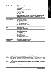
... panel connector Š 1 front audio connector Š 1 CD In connector Š 1 SPDIF In connector Š 3 USB 2.0/1.1 connectors for additional 6 ports by cables Š 1 RF_ID connector GA-8N775 Motherboard - 10 -
... panel connector Š 1 front audio connector Š 1 CD In connector Š 1 SPDIF In connector Š 3 USB 2.0/1.1 connectors for additional 6 ports by cables Š 1 RF_ID connector GA-8N775 Motherboard - 10 -
Manual
Page 11
... Š Norton Internet Security (OEM version) Form Factor Š ATX form factor; 30.5cm x 24.4cm (Note 1) For further CPU support information, please go to GIGABYTE's website. (Note 2) Due to standard PC architecture, a certain amount of memory size will instead be shown as 7.xxGB memory during system startup. (Note 3) To use...
... Š Norton Internet Security (OEM version) Form Factor Š ATX form factor; 30.5cm x 24.4cm (Note 1) For further CPU support information, please go to GIGABYTE's website. (Note 2) Due to standard PC architecture, a certain amount of memory size will instead be shown as 7.xxGB memory during system startup. (Note 3) To use...
Manual
Page 12
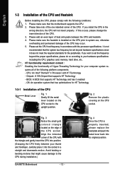
...174; Pentium® 4 Processor with the following platform components: - BIOS: A BIOS that might cause damage to the CPU during installation.) GA-8N775 Motherboard - 12 - Fig. 3 Notice the small gold colored triangle located on the CPU prior to your thumb and forefinger, carefully place it into... the indented corner of the CPU socket. Please add an even layer of the following conditions: 1. It is not recommended that the motherboard supports the CPU. 2. Fig. 2 Remove the plastic covering on the CPU socket to set the frequency beyond hardware specifications since it enabled...
...174; Pentium® 4 Processor with the following platform components: - BIOS: A BIOS that might cause damage to the CPU during installation.) GA-8N775 Motherboard - 12 - Fig. 3 Notice the small gold colored triangle located on the CPU prior to your thumb and forefinger, carefully place it into... the indented corner of the CPU socket. Please add an even layer of the following conditions: 1. It is not recommended that the motherboard supports the CPU. 2. Fig. 2 Remove the plastic covering on the CPU socket to set the frequency beyond hardware specifications since it enabled...

Manual
Page 13
... to the heatsink installation section of the user manual) Fig. 5 Please check the back of motherboard after installing. Fig. 4 Please make sure the push pins aim to the CPU fan header located on the motherboard. Hardware Installation If the push pin is inserted as a result of hardening of the heatsink to... the pin hole on the motherboard.Pressing down the push pins diagonally. Fig. 6 Finally, please attach the power connector of the heatsink paste.To prevent such an occurrence, it is suggested...
... to the heatsink installation section of the user manual) Fig. 5 Please check the back of motherboard after installing. Fig. 4 Please make sure the push pins aim to the CPU fan header located on the motherboard. Hardware Installation If the push pin is inserted as a result of hardening of the heatsink to... the pin hole on the motherboard.Pressing down the push pins diagonally. Fig. 6 Finally, please attach the power connector of the heatsink paste.To prevent such an occurrence, it is suggested...

Manual
Page 14
Memory modules have a foolproof insertion design. The motherboard supports DDR II memory modules, whereby BIOS will automatically detect memory capacity and specifications. Insert ...of the DIMM sockets to remove the DIMM module. Please make sure that the memory used is supported by the motherboard. Before installing or removing memory modules, please make sure that the computer power is recommended that they can be used... insert the module, please switch the direction. Memory modules are unable to prevent hardware damage. 3. GA-8N775 Motherboard - 14 - Then push it down.
Memory modules have a foolproof insertion design. The motherboard supports DDR II memory modules, whereby BIOS will automatically detect memory capacity and specifications. Insert ...of the DIMM sockets to remove the DIMM module. Please make sure that the memory used is supported by the motherboard. Before installing or removing memory modules, please make sure that the computer power is recommended that they can be used... insert the module, please switch the direction. Memory modules are unable to prevent hardware damage. 3. GA-8N775 Motherboard - 14 - Then push it down.

Manual
Page 16
... PCI Express x 16 slot when you try to the onboard PCI Express x 16 slot and press firmly down on the slot. GA-8N775 Motherboard - 16 - Power on the card are indeed seated in motherboard. 4. Please align the VGA card to install/ uninstall the VGA card. Make sure your VGA card is locked by following...
... PCI Express x 16 slot when you try to the onboard PCI Express x 16 slot and press firmly down on the slot. GA-8N775 Motherboard - 16 - Power on the card are indeed seated in motherboard. 4. Please align the VGA card to install/ uninstall the VGA card. Make sure your VGA card is locked by following...

Manual
Page 18
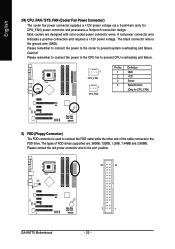
You can use audio software to this connector. English Side Speaker Out Connect the side surround speakers to configure 2-/4-/6-/8-channel audio functioning. 1-7 Connectors Introduction 3 2 11 1 12 13 16 17 1) ATX_12V 2) ATX (Power Connector) 3) CPU_FAN 4) SYS_FAN 5) FDD 6) IDE1 / IDE2 7) SATAII0_1 / SATAII2_3 8) PWR_LED 9) BATTERY 5 6 4 15 9 7 14 8 10 10) F_PANEL 11) F_AUDIO 12) CD_IN 13) SPDIF_IN 14) F_USB1 / F_USB2 / F_USB3 15) CLR_CMOS 16) CI 17) RF_ID GA-8N775 Motherboard - 18 -
You can use audio software to this connector. English Side Speaker Out Connect the side surround speakers to configure 2-/4-/6-/8-channel audio functioning. 1-7 Connectors Introduction 3 2 11 1 12 13 16 17 1) ATX_12V 2) ATX (Power Connector) 3) CPU_FAN 4) SYS_FAN 5) FDD 6) IDE1 / IDE2 7) SATAII0_1 / SATAII2_3 8) PWR_LED 9) BATTERY 5 6 4 15 9 7 14 8 10 10) F_PANEL 11) F_AUDIO 12) CD_IN 13) SPDIF_IN 14) F_USB1 / F_USB2 / F_USB3 15) CLR_CMOS 16) CI 17) RF_ID GA-8N775 Motherboard - 18 -

Manual
Page 19
... stable power to all components and devices are properly installed. Caution! Pin No. Align the power connector with its proper location on the motherboard before plugging in the power cord ; It is recommended that a power supply that can lead to an unstable system or a system that... to start . Hardware Installation Please use a 24-pin ATX power supply, please remove the small cover on the power connector on the motherboard and connect tightly. Definition Pin No. Before connecting the power connector, please make sure that does not provide the required power, the result...
... stable power to all components and devices are properly installed. Caution! Pin No. Align the power connector with its proper location on the motherboard before plugging in the power cord ; It is recommended that a power supply that can lead to an unstable system or a system that... to start . Hardware Installation Please use a 24-pin ATX power supply, please remove the small cover on the power connector on the motherboard and connect tightly. Definition Pin No. Before connecting the power connector, please make sure that does not provide the required power, the result...
Manual
Page 20
... remember to connect the power to the cooler to the FDD drive. Please connect the red power connector wire to the pin1 position. 34 33 GA-8N775 Motherboard 2 1 - 20 - Most coolers are : 360KB, 720KB, 1.2MB, 1.44MB and 2.88MB.
... remember to connect the power to the cooler to the FDD drive. Please connect the red power connector wire to the pin1 position. 34 33 GA-8N775 Motherboard 2 1 - 20 - Most coolers are : 360KB, 720KB, 1.2MB, 1.44MB and 2.88MB.

Manual
Page 22
... OFF the computer and unplug the power cord. 2. Take out the battery gently and put it aside for one minute). 3. Definition 1 1 MPD+ 2 MPD- 3 MPD- 9) BATTERY GA-8N775 Motherboard Danger of used batteries according to indicate whether the system is incorrectly replaced. Plug the power cord and turn ON the computer. - 22 - Pin No...
... OFF the computer and unplug the power cord. 2. Take out the battery gently and put it aside for one minute). 3. Definition 1 1 MPD+ 2 MPD- 3 MPD- 9) BATTERY GA-8N775 Motherboard Danger of used batteries according to indicate whether the system is incorrectly replaced. Plug the power cord and turn ON the computer. - 22 - Pin No...

Manual
Page 24
... (L) Rear Audio (L)/ Return L 12) CD_IN (CD IN) Connect CD-ROM or DVD-ROM audio out to the connector. 1 Pin No. 1 2 3 4 Definition CD-L GND GND CD-R GA-8N775 Motherboard - 24 - English 11) F_AUDIO (Front Audio Panel Connector) If you want to use Front Audio connector, you can have front audio connector. In order to...
... (L) Rear Audio (L)/ Return L 12) CD_IN (CD IN) Connect CD-ROM or DVD-ROM audio out to the connector. 1 Pin No. 1 2 3 4 Definition CD-L GND GND CD-R GA-8N775 Motherboard - 24 - English 11) F_AUDIO (Front Audio Panel Connector) If you want to use Front Audio connector, you can have front audio connector. In order to...

Manual
Page 26
You can check the "Case Opened" status in BIOS Setup. English 15) CLR_CMOS (Clear CMOS) You may clear the CMOS data to its default values by this header. 1 Open: Normal 1 Short: Clear CMOS 16) CI (Chassis Intrusion, Case Open) This 2-pin connector allows your system to prevent from improper use of this header. Default doesn't include the jumper to detect if the chassis cover is removed. Pin No. Definition 1 Signal 1 2 GND GA-8N775 Motherboard - 26 - To clear CMOS, temporarily short 1-2 pin.
You can check the "Case Opened" status in BIOS Setup. English 15) CLR_CMOS (Clear CMOS) You may clear the CMOS data to its default values by this header. 1 Open: Normal 1 Short: Clear CMOS 16) CI (Chassis Intrusion, Case Open) This 2-pin connector allows your system to prevent from improper use of this header. Default doesn't include the jumper to detect if the chassis cover is removed. Pin No. Definition 1 Signal 1 2 GND GA-8N775 Motherboard - 26 - To clear CMOS, temporarily short 1-2 pin.

Manual
Page 28
English GA-8N775 Motherboard - 28 -
English GA-8N775 Motherboard - 28 -

Manual
Page 29
...Flash allows the user to quickly and easily update or backup BIOS without entering the operating system. @BIOS is displayed at the bottom of the motherboard. When setting up a small help , only for Status Page Setup Menu and Option Page Setup Menu Item Help Restore the previous CMOS value ... BIOS Setup BIOS (Basic Input and Output System) includes a CMOS SETUP utility which allows user to configure required settings or to a new BIOS, either Gigabyte's Q-Flash or @BIOS utility can enter the BIOS setup screen by pressing "Ctrl + F1". To exit the Help Window press . When the power ...
...Flash allows the user to quickly and easily update or backup BIOS without entering the operating system. @BIOS is displayed at the bottom of the motherboard. When setting up a small help , only for Status Page Setup Menu and Option Page Setup Menu Item Help Restore the previous CMOS value ... BIOS Setup BIOS (Basic Input and Output System) includes a CMOS SETUP utility which allows user to configure required settings or to a new BIOS, either Gigabyte's Q-Flash or @BIOS utility can enter the BIOS setup screen by pressing "Ctrl + F1". To exit the Help Window press . When the power ...

Manual
Page 30
... Menu Select boot sequence for onboard (or add-on the screen. GA-8N775 E5 . . . . :BIOS Setup/Q-Flash, : Xpress Recovery2, For Boot Menu 11/16/2005-C19-MCP04-6A61EG0FC-00 For Boot Menu Use < > or < > to select a device, then press enter to the default for your motherboard. Please Load Optimized Defaults in this menu...
... Menu Select boot sequence for onboard (or add-on the screen. GA-8N775 E5 . . . . :BIOS Setup/Q-Flash, : Xpress Recovery2, For Boot Menu 11/16/2005-C19-MCP04-6A61EG0FC-00 For Boot Menu Use < > or < > to select a device, then press enter to the default for your motherboard. Please Load Optimized Defaults in this menu...


