User Manual
Page 2
... of Content Item Checklist 4 GA-8IPXDR-E Series Model List 4 WARNING 4 Chapter 1 Introduction 6 Features Summary 6 GA-8IPXDR-E(C) Motherboard Layout 8 Chapter 2 Hardware Installation Process 9 Step 1: Install the Central Processing Unit (CPU 10 Step 1-1: ...and power supply 18 Step 4-1: I/O Back Panel Introduction 18 Step 4-2: Connectors Introduction 20 Step 4-3: Jumper Setting Introduction 30 Chapter 3 BIOS Setup 36 Main ...38 Advanced 41 Advanced Configuration 42 Chipset Configuration ...44 Power Management Configuration 45 PCI-X Configuration ...46 Peripheral Configuration 47 ...
... of Content Item Checklist 4 GA-8IPXDR-E Series Model List 4 WARNING 4 Chapter 1 Introduction 6 Features Summary 6 GA-8IPXDR-E(C) Motherboard Layout 8 Chapter 2 Hardware Installation Process 9 Step 1: Install the Central Processing Unit (CPU 10 Step 1-1: ...and power supply 18 Step 4-1: I/O Back Panel Introduction 18 Step 4-2: Connectors Introduction 20 Step 4-3: Jumper Setting Introduction 30 Chapter 3 BIOS Setup 36 Main ...38 Advanced 41 Advanced Configuration 42 Chipset Configuration ...44 Power Management Configuration 45 PCI-X Configuration ...46 Peripheral Configuration 47 ...
User Manual
Page 3
Table of Content Chapter 4 Technical Reference 60 GA-8IPXDR-E System Block Diagram 60 Chapter 5 Appendix 61 Appendix A: Intel Network Driver Installation 61 Appendix B: INF Update Installation (Driver for chipset 63 Appendix C: ATI Rage XL VGA Driver Installation 64 Appexdix D: Adaptec SCSI Driver Installation 65 Appendix E: Utilites Installation 66 Appendix F: About Updateing Latest version of BIOS 66 Appendix G: IPMI Connector Pin Definition 67 Appendix H: Acronyms 68 Technical Support/RMA Sheet 70 3
Table of Content Chapter 4 Technical Reference 60 GA-8IPXDR-E System Block Diagram 60 Chapter 5 Appendix 61 Appendix A: Intel Network Driver Installation 61 Appendix B: INF Update Installation (Driver for chipset 63 Appendix C: ATI Rage XL VGA Driver Installation 64 Appexdix D: Adaptec SCSI Driver Installation 65 Appendix E: Utilites Installation 66 Appendix F: About Updateing Latest version of BIOS 66 Appendix G: IPMI Connector Pin Definition 67 Appendix H: Acronyms 68 Technical Support/RMA Sheet 70 3

User Manual
Page 7
... ATI Rage XL PCI VGA Chipset On-Board SCSI y Adaptec 7902W Ultra 320 SCSI Chipset PS/2 Connector y PS/2 Keyboard interface and PS/2 Mouse interace BIOS y Licensed AMI BIOS, 4M bit FWH Additional Features y Wake on LAN y AC Recovery y IPMI V1.0 (Winbond BMC) y Intel® RADIOS circuits support both Intel® RADOIS and...
... ATI Rage XL PCI VGA Chipset On-Board SCSI y Adaptec 7902W Ultra 320 SCSI Chipset PS/2 Connector y PS/2 Keyboard interface and PS/2 Mouse interace BIOS y Licensed AMI BIOS, 4M bit FWH Additional Features y Wake on LAN y AC Recovery y IPMI V1.0 (Winbond BMC) y Intel® RADIOS circuits support both Intel® RADOIS and...
User Manual
Page 8
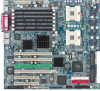
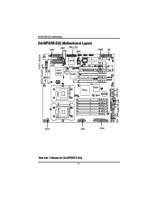
GA-8IPXDR-E(C) Motherboard GA-8IPXDR-E(C) Motherboard Layout FDD1 USB1 IPMI_CON IDE1 BIOS COM2 J20 *SCSI1 (Channel *SCSI2 (Channel B) A) ICH3-S IDE2 *SCSI 7902W CLR_COMS BT1 P64H2 SIO NS Wake on LAN PCI_6 PCI_5 PCI_4 ATI Rage XL PCI-X_3 PCI-X_2 PCI-X_1 CPU2 E7501 P64H2 82546EB J4 (B-1) J1 (A-1) J5 (B-2) J2 (A-2) J6 (B-3) J3 (A-3) 604 PIN Socket 604 PIN Socket CPU1 (Install First) ATX2 ATX1 ATX3 CN1 USB2 COM1LPT VGA LAN1 LAN2 Note that * indicates for GA-8IPXDR-E Only 8
GA-8IPXDR-E(C) Motherboard GA-8IPXDR-E(C) Motherboard Layout FDD1 USB1 IPMI_CON IDE1 BIOS COM2 J20 *SCSI1 (Channel *SCSI2 (Channel B) A) ICH3-S IDE2 *SCSI 7902W CLR_COMS BT1 P64H2 SIO NS Wake on LAN PCI_6 PCI_5 PCI_4 ATI Rage XL PCI-X_3 PCI-X_2 PCI-X_1 CPU2 E7501 P64H2 82546EB J4 (B-1) J1 (A-1) J5 (B-2) J2 (A-2) J6 (B-3) J3 (A-3) 604 PIN Socket 604 PIN Socket CPU1 (Install First) ATX2 ATX1 ATX3 CN1 USB2 COM1LPT VGA LAN1 LAN2 Note that * indicates for GA-8IPXDR-E Only 8

User Manual
Page 9
Install supporting software tools Step 4 Step 5 Step 4 Step1 Step 4 Step 3 Step 4 Step 4 Step 4 Step 2 9 Hardware Installation Process Chapter 2 Hardware Installation Process To set up your computer, you must complete the following setups: Step 1- Setup BIOS software Step 6- Install expansion cards Step 4- Install memory modules Step 3- Connect ribbon cables, cabinet wires, and power supply Step 5- Install the Central Processing Unit (CPU) Step 2-
Install supporting software tools Step 4 Step 5 Step 4 Step1 Step 4 Step 3 Step 4 Step 4 Step 4 Step 2 9 Hardware Installation Process Chapter 2 Hardware Installation Process To set up your computer, you must complete the following setups: Step 1- Setup BIOS software Step 6- Install expansion cards Step 4- Install memory modules Step 3- Connect ribbon cables, cabinet wires, and power supply Step 5- Install the Central Processing Unit (CPU) Step 2-

User Manual
Page 15
To install the memory module, just push it can vary between sockets. The BIOS will automatically detects memory type and size. Registered DDR Notch J4 (B-1) J1 (A-1) J5 (B-2) J2 (A-2) J6 (B-3) J3 (A-3) 15 DDR socket 1 uses 1 bank, DDR socket 2& 3 share the remaining 2 banks. Hardware Installation Process Step 2: Install memory modules The motherboard has 6 dual inline memory module (DIMM) sockets, but it vertically into the DIMM Slot .The DIMM module can only fit in one direction due to the notch.Memory size can only support a maximum of 3 banks DDR memory.
To install the memory module, just push it can vary between sockets. The BIOS will automatically detects memory type and size. Registered DDR Notch J4 (B-1) J1 (A-1) J5 (B-2) J2 (A-2) J6 (B-3) J3 (A-3) 15 DDR socket 1 uses 1 bank, DDR socket 2& 3 share the remaining 2 banks. Hardware Installation Process Step 2: Install memory modules The motherboard has 6 dual inline memory module (DIMM) sockets, but it vertically into the DIMM Slot .The DIMM module can only fit in one direction due to the notch.Memory size can only support a maximum of 3 banks DDR memory.
User Manual
Page 17
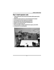
Install related driver from the computer. 3. Be sure the metal contacts on the computer, if necessary, setup BIOS utility of the expansion card. 6. Replace the screw to secure the slot bracket of expansion card from BIOS. 8. Remove your computer's chassis cover. 7. Hardware Installation Process Step 3: Install expansion cards 1. Read the related expansion card...
Install related driver from the computer. 3. Be sure the metal contacts on the computer, if necessary, setup BIOS utility of the expansion card. 6. Replace the screw to secure the slot bracket of expansion card from BIOS. 8. Remove your computer's chassis cover. 7. Hardware Installation Process Step 3: Install expansion cards 1. Read the related expansion card...
User Manual
Page 36
...Menu - Exit current page and return to the item in battery-backed CMOS RAM so that allows users to enter Setup. GA-8IPXDR-E(C) Motherboard Chapter 3 BIOS Setup BIOS Setup is turned off. ENTERINGSETUP Power ON the computer and press immediately will allow you to modify the basic system configuration. ...This type of the BIOS Setup Program. The program that it retains the Setup information when the power is an overview of information is stored in the right...
...Menu - Exit current page and return to the item in battery-backed CMOS RAM so that allows users to enter Setup. GA-8IPXDR-E(C) Motherboard Chapter 3 BIOS Setup BIOS Setup is turned off. ENTERINGSETUP Power ON the computer and press immediately will allow you to modify the basic system configuration. ...This type of the BIOS Setup Program. The program that it retains the Setup information when the power is an overview of information is stored in the right...

User Manual
Page 37
z Main This setup page includes all the items of first boot function features. z Boot This setup page include all the items in standard compatible BIOS. z Advanced This setup page includes all the items of the screen. z Exit There are five optionsin this selection: Exit Saving Changes, Exit ... the system and setup. To exit the Help Window press . It allows you to use and the possible selections for the highlighted item. BIOS Setup GETTINGHELP Main Menu The on-line description of the highlighted setup function is displayed at the bottom of AMI special enhanced features. (ex:...
z Main This setup page includes all the items of first boot function features. z Boot This setup page include all the items in standard compatible BIOS. z Advanced This setup page includes all the items of the screen. z Exit There are five optionsin this selection: Exit Saving Changes, Exit ... the system and setup. To exit the Help Window press . It allows you to use and the possible selections for the highlighted item. BIOS Setup GETTINGHELP Main Menu The on-line description of the highlighted setup function is displayed at the bottom of AMI special enhanced features. (ex:...
User Manual
Page 38
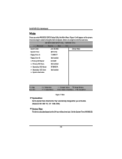
... that the "Day" automatically changed after you enter AMI BIOS CMOS Setup Utility, the Main Menu (Figure 1) will appear on the 24-hour military time clock. Use arrow keys to select among the items and press to accept or enter the sub-menu. GA-8IPXDR-E(C) Motherboard Main Once you set the date. (Weekend...
... that the "Day" automatically changed after you enter AMI BIOS CMOS Setup Utility, the Main Menu (Figure 1) will appear on the 24-hour military time clock. Use arrow keys to select among the items and press to accept or enter the sub-menu. GA-8IPXDR-E(C) Motherboard Main Once you set the date. (Weekend...
User Manual
Page 39
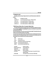
ARMD: Use for ATAPI CD/DVD-ROM drives. BIOS Setup Floppy Drive A/B This category identifies the type of floppy disk drive A or drive B that the specifications of your hard disk vendor or the system ...
ARMD: Use for ATAPI CD/DVD-ROM drives. BIOS Setup Floppy Drive A/B This category identifies the type of floppy disk drive A or drive B that the specifications of your hard disk vendor or the system ...
User Manual
Page 40
Off If a hard disk has not been installed select NONE and press . GA-8IPXDR-E(C) Motherboard Fast Programmed I/O Mode This field only shows the information of Fast Programmed I/O Mode. 32 Bit Transfer Mode Enables 32 bit access to maximize the hard disk data transfer rate. System Information This category displays the following system information: the Processor type, Speed, Cache Size, Total Memory Size, Memory Resized DIMM, BIOS version, BIOS Release Date and System Product Name. 40 Option: On (Default Value);
Off If a hard disk has not been installed select NONE and press . GA-8IPXDR-E(C) Motherboard Fast Programmed I/O Mode This field only shows the information of Fast Programmed I/O Mode. 32 Bit Transfer Mode Enables 32 bit access to maximize the hard disk data transfer rate. System Information This category displays the following system information: the Processor type, Speed, Cache Size, Total Memory Size, Memory Resized DIMM, BIOS version, BIOS Release Date and System Product Name. 40 Option: On (Default Value);

User Manual
Page 41
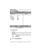
...operation. A user can change the system's default boot-up sequence, keyboard operation, shadowing and security, etc. 41 Advanced AMI BIOS NEW SETUP Utility - VERSION 3.31a Main Advanced Security Boot Exit ` Advanced Configuration ` Chipset Configuration ` Power Management Configuration `... PCI-X Configuration `Peripheral Configuration `Hardware Monitor Configuration [Setup Help] BIOS Setup F1: Help Esc: Exit KL: Select Item IJ: Select Menu + -: Change Values F5: Setup Defaults Enter: Select Sub...
...operation. A user can change the system's default boot-up sequence, keyboard operation, shadowing and security, etc. 41 Advanced AMI BIOS NEW SETUP Utility - VERSION 3.31a Main Advanced Security Boot Exit ` Advanced Configuration ` Chipset Configuration ` Power Management Configuration `... PCI-X Configuration `Peripheral Configuration `Hardware Monitor Configuration [Setup Help] BIOS Setup F1: Help Esc: Exit KL: Select Item IJ: Select Menu + -: Change Values F5: Setup Defaults Enter: Select Sub...
User Manual
Page 42
Enabled Set this option "Enable" to permit BIOS to skip certain tests while booting. The indicates DISPLAY ONLY 42 VERSION 3.31a Main Advanced Security Boot Exit Advanced Configuration [Setup Help] Quick ...: Setup Defaults Enter: Select Sub-Menu F10: Save&Exit Figure 2-1: Advanced Configuration Advanced Configuration ` Quick Boot This setting allows BIOS to skip certain tests while booting. (Default Value) Disabled Disable this function. This will decrease the time needed to boot the system. GA-8IPXDR-E(C) Motherboard Advanced Configuration AMI BIOS NEW SETUP Utility -
Enabled Set this option "Enable" to permit BIOS to skip certain tests while booting. The indicates DISPLAY ONLY 42 VERSION 3.31a Main Advanced Security Boot Exit Advanced Configuration [Setup Help] Quick ...: Setup Defaults Enter: Select Sub-Menu F10: Save&Exit Figure 2-1: Advanced Configuration Advanced Configuration ` Quick Boot This setting allows BIOS to skip certain tests while booting. (Default Value) Disabled Disable this function. This will decrease the time needed to boot the system. GA-8IPXDR-E(C) Motherboard Advanced Configuration AMI BIOS NEW SETUP Utility -

User Manual
Page 43
... press 'F4' than 'DEL'. When the COM port is determined, users can either select COMA or COMB to select MP (Multi Processors) system supported version. BIOS Setup ` MPS Version for C.R Baud Rate and the C.R after Post. COMA/COMB User can adjust the items for O.S This option allows a user to enable the...
... press 'F4' than 'DEL'. When the COM port is determined, users can either select COMA or COMB to select MP (Multi Processors) system supported version. BIOS Setup ` MPS Version for C.R Baud Rate and the C.R after Post. COMA/COMB User can adjust the items for O.S This option allows a user to enable the...

User Manual
Page 44
... boost in multi-tasking Enabling Hyper-Threading Technology requires a computer system with an Intel Pentium 4 processor at 3.06 GHz or higher, a chipset and BIOS that utilize this technology, and an operating system that includes optimizations for this technology. GA-8IPXDR-E(C) Motherboard Chipset Configuration AMI BIOS NEW SETUP Utility - Enabled Disabled Enable Intel Hyper Threading.
... boost in multi-tasking Enabling Hyper-Threading Technology requires a computer system with an Intel Pentium 4 processor at 3.06 GHz or higher, a chipset and BIOS that utilize this technology, and an operating system that includes optimizations for this technology. GA-8IPXDR-E(C) Motherboard Chipset Configuration AMI BIOS NEW SETUP Utility - Enabled Disabled Enable Intel Hyper Threading.

User Manual
Page 45
... Figure 2-3: Power Management Configuration Power Management Configuration The Power Management Configuration allows you to the last sate when AC power is re-plugged. BIOS Setup Power Management Configuration AMI BIOS NEW SETUP Utility - Last State Set system to reduce system power consumption through different saving power methods for various devices. ` System After...
... Figure 2-3: Power Management Configuration Power Management Configuration The Power Management Configuration allows you to the last sate when AC power is re-plugged. BIOS Setup Power Management Configuration AMI BIOS NEW SETUP Utility - Last State Set system to reduce system power consumption through different saving power methods for various devices. ` System After...

User Manual
Page 46
GA-8IPXDR-E(C) Motherboard PCI-X Configuration AMI BIOS NEW SETUP Utility - VERSION 3.31a Main Advanced Security Boot Exit PCI-X Configuration [Setup Help] Data Parity Error Recovery Relaxed Ordering Enabled Enabled F1: Help Esc: ...
GA-8IPXDR-E(C) Motherboard PCI-X Configuration AMI BIOS NEW SETUP Utility - VERSION 3.31a Main Advanced Security Boot Exit PCI-X Configuration [Setup Help] Data Parity Error Recovery Relaxed Ordering Enabled Enabled F1: Help Esc: ...
User Manual
Page 47
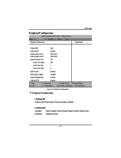
VERSION 3.31a Main Advanced Security Boot Exit Peripheral Configuration BIOS Setup [Setup Help] OnBoard IDE Both OnBoard FDC Enabled Onboard Serial Port A Onboard Serial Port B 3F8/COM1 2F8/COM2 Onboard Parallel Port 378 Parallel Port ... (Default Value), Primary, Secondary, Disabled ` OnBoard FDC Enabled Select "Enabled" to active Onboard Floppy Controller. (Default Value) Disabled Disable this function. 47 Peripheral Configuration AMI BIOS NEW SETUP Utility -
VERSION 3.31a Main Advanced Security Boot Exit Peripheral Configuration BIOS Setup [Setup Help] OnBoard IDE Both OnBoard FDC Enabled Onboard Serial Port A Onboard Serial Port B 3F8/COM1 2F8/COM2 Onboard Parallel Port 378 Parallel Port ... (Default Value), Primary, Secondary, Disabled ` OnBoard FDC Enabled Select "Enabled" to active Onboard Floppy Controller. (Default Value) Disabled Disable this function. 47 Peripheral Configuration AMI BIOS NEW SETUP Utility -
User Manual
Page 49
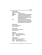
... user to provide asymmetric bi-directional data transfer driven by the host device. Enabled Enables support for legacy USB Disabled Disables support for legacy USB. BIOS Setup ` Parallel Port Mode This option specifies the parallel mode. Bi-Directional Use this function. ` USB Legacy Support This option allows user to 2.5Mbit/s. Normal...
... user to provide asymmetric bi-directional data transfer driven by the host device. Enabled Enables support for legacy USB Disabled Disables support for legacy USB. BIOS Setup ` Parallel Port Mode This option specifies the parallel mode. Bi-Directional Use this function. ` USB Legacy Support This option allows user to 2.5Mbit/s. Normal...


