
Manual
Page 1
GA-8IP775 Series Intel® Pentium® 4 LGA775 Processor Motherboard User's Manual Rev. 1003 12ME-8IP775-1003
GA-8IP775 Series Intel® Pentium® 4 LGA775 Processor Motherboard User's Manual Rev. 1003 12ME-8IP775-1003

Manual
Page 2
Motherboard GA-8IP775/GA-8IP775-G Sep. 10, 2004 Motherboard GA-8IP775/GA-8IP775-G Sep. 10, 2004
Motherboard GA-8IP775/GA-8IP775-G Sep. 10, 2004 Motherboard GA-8IP775/GA-8IP775-G Sep. 10, 2004
Manual
Page 4
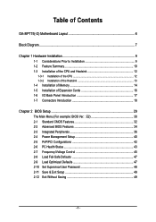
Table of Contents GA-8IP775(-G) Motherboard Layout 6 Block Diagram ...7 Chapter 1 Hardware Installation 9 1-1 Considerations Prior to Installation 9 1-2 Feature Summary 10 1-3 Installation of the CPU and Heatsink 12 1-3-1 Installation of the CPU 12 1-3-2 ...
Table of Contents GA-8IP775(-G) Motherboard Layout 6 Block Diagram ...7 Chapter 1 Hardware Installation 9 1-1 Considerations Prior to Installation 9 1-2 Feature Summary 10 1-3 Installation of the CPU and Heatsink 12 1-3-1 Installation of the CPU 12 1-3-2 ...
Manual
Page 6
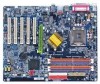
GA-8IP775(-G) Motherboard Layout KB_MS CPU_FAN ATX_12V COMA FDD ATX COMB LPT R_USB LGA775 IDE1 IDE2 GA-8IP775(-G) DDR1 DDR2 USB LAN (*) AUDIO CD_IN Intel® 865P Marvell F_AUDIO 8001 (*) AGP DDR4 DDR3 IT8712 CODEC SUR_CEN DUAL CHANNEL DDR PCI1 SATA P4 Titan PCI2 CI IR_CIR PCI3 PCI4 BIOS PCI5 GAME SPDIF_IO ICH5 SATA1 SATA0 BAT CLR_CMOS SYS_FAN INFO_LINK F_PANEL F_USB2 PWR_LED F_USB1 (*) Only for GA-8IP775-G. - 6 -
GA-8IP775(-G) Motherboard Layout KB_MS CPU_FAN ATX_12V COMA FDD ATX COMB LPT R_USB LGA775 IDE1 IDE2 GA-8IP775(-G) DDR1 DDR2 USB LAN (*) AUDIO CD_IN Intel® 865P Marvell F_AUDIO 8001 (*) AGP DDR4 DDR3 IT8712 CODEC SUR_CEN DUAL CHANNEL DDR PCI1 SATA P4 Titan PCI2 CI IR_CIR PCI3 PCI4 BIOS PCI5 GAME SPDIF_IO ICH5 SATA1 SATA0 BAT CLR_CMOS SYS_FAN INFO_LINK F_PANEL F_USB2 PWR_LED F_USB1 (*) Only for GA-8IP775-G. - 6 -
Manual
Page 9
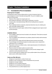
...RAM). 4. It is switched off the computer and unplug its components. 5. Installation Notices 1. Prior to the installation of the motherboard or any installation steps or have these items on an uneven surface. 7. Thus, prior to improper installation. 4. Please verify ... you the power supply is best to be an unofficial Gigabyte product. - 9 - Instances of Non-Warranty 1. English Chapter 1 Hardware Installation 1-1 Considerations Prior to Installation Preparing Your Computer The motherboard contains numerous delicate electronic circuits and components which can lead to...
...RAM). 4. It is switched off the computer and unplug its components. 5. Installation Notices 1. Prior to the installation of the motherboard or any installation steps or have these items on an uneven surface. 7. Thus, prior to improper installation. 4. Please verify ... you the power supply is best to be an unofficial Gigabyte product. - 9 - Instances of Non-Warranty 1. English Chapter 1 Hardware Installation 1-1 Considerations Prior to Installation Preparing Your Computer The motherboard contains numerous delicate electronic circuits and components which can lead to...
Manual
Page 10
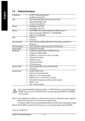
English 1-2 Feature Summary M otherboard CPU Chip set Mem ory Slo ts IDE Connections FDD Connections Onboard SATA Peripherals Onboard LAN (*) Onboard Audio w GA-8IP775 Series Motherboard: GA-8IP 775-G/GA-8 IP775 w Supports the latest Intel® Pentium® 4 LGA775 CPU w Supports 800/533MHz FSB w L2 cache varies with CPU w Northbridge: Intel® 865P w ... DDR400. (*) Only for system usage and therefore the actual memory size is selected as CPU frequency, memory will support DDR400 memory module. GA-8IP775 Series Motherboard - 10 - For example, 4 GB of memory is reserved for...
English 1-2 Feature Summary M otherboard CPU Chip set Mem ory Slo ts IDE Connections FDD Connections Onboard SATA Peripherals Onboard LAN (*) Onboard Audio w GA-8IP775 Series Motherboard: GA-8IP 775-G/GA-8 IP775 w Supports the latest Intel® Pentium® 4 LGA775 CPU w Supports 800/533MHz FSB w L2 cache varies with CPU w Northbridge: Intel® 865P w ... DDR400. (*) Only for system usage and therefore the actual memory size is selected as CPU frequency, memory will support DDR400 memory module. GA-8IP775 Series Motherboard - 10 - For example, 4 GB of memory is reserved for...
Manual
Page 12
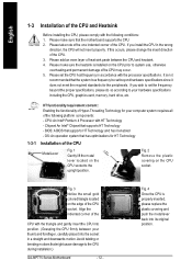
Please take note of the one indented corner of the CPU. 3. Please make sure that the motherboard supports the CPU. 2. CPU: An Intel® Pentium 4 Processor with the processor specifications. Fig. 4 Once the CPU is installed on the edge of the CPU ... wrong direction, the CPU will not insert properly. Fig. 2 Rem ov e the pl astic covering on the CPU socket to the CPU during installation.) GA-8IP775 Series Motherboard - 12 - Avoid twisting or bending motions thatmightcause damage to the upright position. Align the indented corner of the CPU with the triangle and gently insert...
Please take note of the one indented corner of the CPU. 3. Please make sure that the motherboard supports the CPU. 2. CPU: An Intel® Pentium 4 Processor with the processor specifications. Fig. 4 Once the CPU is installed on the edge of the CPU ... wrong direction, the CPU will not insert properly. Fig. 2 Rem ov e the pl astic covering on the CPU socket to the CPU during installation.) GA-8IP775 Series Motherboard - 12 - Avoid twisting or bending motions thatmightcause damage to the upright position. Align the indented corner of the CPU with the triangle and gently insert...
Manual
Page 14
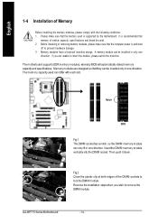
... please make sure that memory of similar capacity, specifications and brand be used is supported by the motherboard. Memory modules have a foolproof insertion design. The motherboard supports DDR memory modules, whereby BIOS will automatically detect memory capacity and specifications. Then push it down....one direction. Insert the DIM M memory module vertically into the DIMM socket. Memory modules are unable to lock the DIMM module. GA-8IP775 Series Motherboard - 14 - Fig.2 Close the plastic clip at both edges of the DIMM sockets to insert the module, please switch the ...
... please make sure that memory of similar capacity, specifications and brand be used is supported by the motherboard. Memory modules have a foolproof insertion design. The motherboard supports DDR memory modules, whereby BIOS will automatically detect memory capacity and specifications. Then push it down....one direction. Insert the DIM M memory module vertically into the DIMM socket. Memory modules are unable to lock the DIMM module. GA-8IP775 Series Motherboard - 14 - Fig.2 Close the plastic clip at both edges of the DIMM sockets to insert the module, please switch the ...
Manual
Page 16
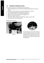
... from the computer. 3. Remove your computer's chassis cover. 7. Power on the card are indeed seated in motherboard. 4. Be sure the metal contacts on the computer, if necessary, setup BIOS utility of the expansion card. 6. GA-8IP775 Series Motherboard - 16 - English 1-5 Installation of Expansion Cards You can install your expansion card by the small white...
... from the computer. 3. Remove your computer's chassis cover. 7. Power on the card are indeed seated in motherboard. 4. Be sure the metal contacts on the computer, if necessary, setup BIOS utility of the expansion card. 6. GA-8IP775 Series Motherboard - 16 - English 1-5 Installation of Expansion Cards You can install your expansion card by the small white...

Manual
Page 18
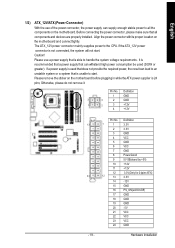
English 1-7 Connectors Introduction 3 1 12 10 11 18 14 16 13 20 6 2 5 19 7 4 17 9 8 15 1) ATX_12V 2) ATX 3) CPU_FAN 4) SYS_FAN 5) IDE1/IDE2 6) FDD 7) SATA0/SATA1 8) PWR_LED 9) F_PANEL 10) F_AUDIO 11) SUR_CEN 12) CD_IN 13) SPDIF_IO 14) IR_CIR 15) F_USB1/F_USB2 16) GAME 17) INFO_LINK 18) CI 19) CLR_CMOS 20) BAT GA-8IP775 Series Motherboard - 18 -
English 1-7 Connectors Introduction 3 1 12 10 11 18 14 16 13 20 6 2 5 19 7 4 17 9 8 15 1) ATX_12V 2) ATX 3) CPU_FAN 4) SYS_FAN 5) IDE1/IDE2 6) FDD 7) SATA0/SATA1 8) PWR_LED 9) F_PANEL 10) F_AUDIO 11) SUR_CEN 12) CD_IN 13) SPDIF_IO 14) IR_CIR 15) F_USB1/F_USB2 16) GAME 17) INFO_LINK 18) CI 19) CLR_CMOS 20) BAT GA-8IP775 Series Motherboard - 18 -
Manual
Page 19
... No. Definition 1 GND 3 4 2 GND 1 2 3 +12V 4 +12V 13 24 - 19 - Align the power connector with its proper location on the motherboard before plugging in while theATX power supplier is 24 pins; The ATX_12V power connector mainly supplies power to start . Please use of the power connector... Hardware Installation Pin No. Before connecting the power connector, please make sure that all the components on the motherboard. English 1/2) ATX_12V/ATX (Power Connector) With the use a power supply that is able to all components and devices are properly installed.
... No. Definition 1 GND 3 4 2 GND 1 2 3 +12V 4 +12V 13 24 - 19 - Align the power connector with its proper location on the motherboard before plugging in while theATX power supplier is 24 pins; The ATX_12V power connector mainly supplies power to start . Please use of the power connector... Hardware Installation Pin No. Before connecting the power connector, please make sure that all the components on the motherboard. English 1/2) ATX_12V/ATX (Power Connector) With the use a power supply that is able to all components and devices are properly installed.
Manual
Page 20
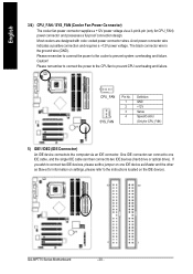
... indicates a positive connection and requires a +12V power voltage. One IDE connector can then connect to the instructions located on the IDE device). 40 39 2 1 GA-8IP775 Series Motherboard - 20 - Caution! Please remem ber to connect the power to the cooler to the computer via a 3-pin/4-pin (only for information on settings, please refer...
... indicates a positive connection and requires a +12V power voltage. One IDE connector can then connect to the instructions located on the IDE device). 40 39 2 1 GA-8IP775 Series Motherboard - 20 - Caution! Please remem ber to connect the power to the cooler to the computer via a 3-pin/4-pin (only for information on settings, please refer...

Manual
Page 22
... 2- Pin 3: NC Pin 4: Data(-) Open:Normal Operation Close: Reset Hardware System Open:Normal Operation Close:Power On/Off Pin 1: LED anode(+) Pin 2: LED cathode(-) NC GA-8IP775 Series Motherboard - 22 - It will blink when the system enters suspend mode. Definition 1 MPD+ 1 2 MPD- 3 MPD- 9) F_PANEL (Front Panel Jumper) Please connect the power LED, PC...
... 2- Pin 3: NC Pin 4: Data(-) Open:Normal Operation Close: Reset Hardware System Open:Normal Operation Close:Power On/Off Pin 1: LED anode(+) Pin 2: LED cathode(-) NC GA-8IP775 Series Motherboard - 22 - It will blink when the system enters suspend mode. Definition 1 MPD+ 1 2 MPD- 3 MPD- 9) F_PANEL (Front Panel Jumper) Please connect the power LED, PC...
Manual
Page 24
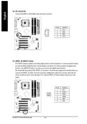
Use SPDIF IN feature only when your local dealer. 26 15 Pin No. 1 2 3 4 5 6 Definition VCC No Pin SPDIF SPDIFI GND GND GA-8IP775 Series Motherboard - 24 - For optional SPDIF_IO cable, please contact your device has digital output function. Be careful with the polarity of providing digital audio to external speakers ...
Use SPDIF IN feature only when your local dealer. 26 15 Pin No. 1 2 3 4 5 6 Definition VCC No Pin SPDIF SPDIFI GND GND GA-8IP775 Series Motherboard - 24 - For optional SPDIF_IO cable, please contact your device has digital output function. Be careful with the polarity of providing digital audio to external speakers ...
Manual
Page 26
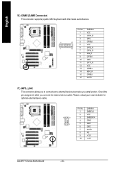
... contact your nearest dealer for optional external device cable. 10 9 2 1 Pin No. 1 2 3 4 5 6 7 8 9 10 Definition SMBCLK VCC SMBDATA GPIO GND GND No Pin NC +12V +12V GA-8IP775 Series Motherboard - 26 - Pin No. English 16) GAME (GAME Connector) This connector supports joystick, MIDI keyboard and other relate audio devices.
... contact your nearest dealer for optional external device cable. 10 9 2 1 Pin No. 1 2 3 4 5 6 7 8 9 10 Definition SMBCLK VCC SMBDATA GPIO GND GND No Pin NC +12V +12V GA-8IP775 Series Motherboard - 26 - Pin No. English 16) GAME (GAME Connector) This connector supports joystick, MIDI keyboard and other relate audio devices.

Manual
Page 28
English 20) BAT(Battery) Danger of used batteries according to erase CM OS... 1.Turn OFF the computer and unplug the power cord. 2.Remove the battery, wait for 30 second. 3.Re-install the battery. 4.Plug the power cord and turn ON the computer. GA-8IP775 Series Motherboard - 28 - Dispose of explosion if batteryis incorrectly replaced. If you want to the manufacturer's instructions. Replace only with the same or equivalent type recommended bythe manufacturer.
English 20) BAT(Battery) Danger of used batteries according to erase CM OS... 1.Turn OFF the computer and unplug the power cord. 2.Remove the battery, wait for 30 second. 3.Re-install the battery. 4.Plug the power cord and turn ON the computer. GA-8IP775 Series Motherboard - 28 - Dispose of explosion if batteryis incorrectly replaced. If you want to the manufacturer's instructions. Replace only with the same or equivalent type recommended bythe manufacturer.
Manual
Page 29
... the appropriate keys to use and the possible selections for the first time, it is displayed at the bottom of the motherboard. Exit current page and return to a new BIOS, either Gigabyte's Q-Flash or @BIOS utility can enter the BIOS setup screen by pressing "Ctrl + F1". When setting up a small... item. Q-Flash allows the user to quickly and easily update or backup BIOS without entering the operating system. @BIOS is turned on the motherboard supplies the necessary power to the CMOS SETUP screen. When the power is a Windows-based utility that you to the CMOS SRAM. The ...
... the appropriate keys to use and the possible selections for the first time, it is displayed at the bottom of the motherboard. Exit current page and return to a new BIOS, either Gigabyte's Q-Flash or @BIOS utility can enter the BIOS setup screen by pressing "Ctrl + F1". When setting up a small... item. Q-Flash allows the user to quickly and easily update or backup BIOS without entering the operating system. @BIOS is turned on the motherboard supplies the necessary power to the CMOS SETUP screen. When the power is a Windows-based utility that you to the CMOS SRAM. The ...
Manual
Page 30
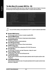
GA-8IP775 Series Motherboard - 30 - If you can't find the setting you enter Award BIOS CMOS Setup Utility, the Main Menu (as figure below) will appear on the screen. ...
GA-8IP775 Series Motherboard - 30 - If you can't find the setting you enter Award BIOS CMOS Setup Utility, the Main Menu (as figure below) will appear on the screen. ...
Manual
Page 32
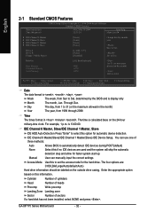
... 2098 Time The times format in the month) 1999 to automatically detect IDE devices during POST(default) Select this option for faster system start up. GA-8IP775 Series Motherboard - 32 - For example, 1 p.m. The time is , , , . Jan. IDE Channel 0 Master(Slave)/IDE Channel 1 Master(Slave) IDE Device Setup. Enter the appropriate option based on...
... 2098 Time The times format in the month) 1999 to automatically detect IDE devices during POST(default) Select this option for faster system start up. GA-8IP775 Series Motherboard - 32 - For example, 1 p.m. The time is , , , . Jan. IDE Channel 0 Master(Slave)/IDE Channel 1 Master(Slave) IDE Device Setup. Enter the appropriate option based on...
Manual
Page 33
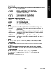
... The POST of the BIOS will be stopped. The value of the base memory is typically 512K for systems with 512K memory installed on the motherboard, or 640K for Japan Area) Disabled Normal Floppy Drive. (Default value) Drive A Drive B Drive A is 3 mode Floppy Drive. Extended Memory The ... not stop for all other errors. All, But Disk/Key The system boot will be prompted. This is present during power up. Halt on the motherboard. it will stop if an error is Enabled). 720K, 3.5" 3.5 inch double-sided drive; 720K byte capacity 1.44M, 3.5" 3.5 inch double-sided drive; 1.44M ...
... The POST of the BIOS will be stopped. The value of the base memory is typically 512K for systems with 512K memory installed on the motherboard, or 640K for Japan Area) Disabled Normal Floppy Drive. (Default value) Drive A Drive B Drive A is 3 mode Floppy Drive. Extended Memory The ... not stop for all other errors. All, But Disk/Key The system boot will be prompted. This is present during power up. Halt on the motherboard. it will stop if an error is Enabled). 720K, 3.5" 3.5 inch double-sided drive; 720K byte capacity 1.44M, 3.5" 3.5 inch double-sided drive; 1.44M ...


