
User Manual
Page 1
...in it . Before you install PCI cards, please remove the Dual BIOS label from PCI slots if there is fully understood and practiced. Example 1: Diamond Vipper V770 golden finger is compatible with AGP 4X(1.5V) specification. The GA-8KNXP / GA-8IK1100 (or any AGP Pro 4X/8X only) motherboards might experience system ... is not supported by adjusting the jumper. When you installing AGP card, please make sure your AGP card is AGP 4X/8X. Note : Although Gigabyte's AG32S(G) graphics card is based on ATi Rage 128 Pro chip, the design of AG32S(G) is compliance with 2X/4X mode AGP slot. If...
...in it . Before you install PCI cards, please remove the Dual BIOS label from PCI slots if there is fully understood and practiced. Example 1: Diamond Vipper V770 golden finger is compatible with AGP 4X(1.5V) specification. The GA-8KNXP / GA-8IK1100 (or any AGP Pro 4X/8X only) motherboards might experience system ... is not supported by adjusting the jumper. When you installing AGP card, please make sure your AGP card is AGP 4X/8X. Note : Although Gigabyte's AG32S(G) graphics card is based on ATi Rage 128 Pro chip, the design of AG32S(G) is compliance with 2X/4X mode AGP slot. If...

User Manual
Page 6
... - 2 - English Table of Content Warning 4 Chapter 1 Introduction 5 Features Summary 5 GA-8KNXP / GA-8IK1100 Motherboard Layout 8 Block Diagram 9 Chapter 2 Hardware Installation Process 11 Step 1: Install the Central Processing Unit (CPU 12 Step 1-1: CPU ... Connect ribbon cables, cabinet wires and power supply 19 Step 4-1: I/O Back Panel Introduction 19 Step 4-2: Connectors Introduction 21 Chapter 3 BIOS Setup 39 The Main Menu (For example: BIOS Ver. : E4 40 Standard CMOS Features 42 Advanced BIOS Features 45 Integrated Peripherals 47 Power Management Setup 53 * Only for...
... - 2 - English Table of Content Warning 4 Chapter 1 Introduction 5 Features Summary 5 GA-8KNXP / GA-8IK1100 Motherboard Layout 8 Block Diagram 9 Chapter 2 Hardware Installation Process 11 Step 1: Install the Central Processing Unit (CPU 12 Step 1-1: CPU ... Connect ribbon cables, cabinet wires and power supply 19 Step 4-1: I/O Back Panel Introduction 19 Step 4-2: Connectors Introduction 21 Chapter 3 BIOS Setup 39 The Main Menu (For example: BIOS Ver. : E4 40 Standard CMOS Features 42 Advanced BIOS Features 45 Integrated Peripherals 47 Power Management Setup 53 * Only for...

User Manual
Page 7
English PnP/PCI Configurations 56 PC Health Status 57 Frequency/Voltage Control 59 Select Language 62 Load Fail-Safe Defaults 63 Load Optimized Defaults 64 Set Supervisor/User Password 65 Save & Exit Setup 66 Exit Without Saving 67 Chapter 4 Technical Reference 69 @BIOS™ Introduction 69 EasyTune™ 4 Introduction 70 DPS2 (Dual Power System 2) Introduction 71 Flash BIOS Method Introduction 72 2- / 4- / 6-Channel Audio Function Introuction 82 Jack-Sensing Introuction 88 Chapter 5 Appendix 91 * Only for GA-8KNXP. - 3 - Table of Content
English PnP/PCI Configurations 56 PC Health Status 57 Frequency/Voltage Control 59 Select Language 62 Load Fail-Safe Defaults 63 Load Optimized Defaults 64 Set Supervisor/User Password 65 Save & Exit Setup 66 Exit Without Saving 67 Chapter 4 Technical Reference 69 @BIOS™ Introduction 69 EasyTune™ 4 Introduction 70 DPS2 (Dual Power System 2) Introduction 71 Flash BIOS Method Introduction 72 2- / 4- / 6-Channel Audio Function Introuction 82 Jack-Sensing Introuction 88 Chapter 5 Appendix 91 * Only for GA-8KNXP. - 3 - Table of Content

User Manual
Page 10
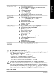
... XP # Only for GA-8IK1100. GA-8KNXP / GA-8IK1100 Motherboard - 6 - English On-Board Peripherals Hardware Monitor On-Board LAN On-Board Sound On-Board IDE RAID* On-Board SATA RAID * Only for HDD y Supports IDE bus master operation y Support ATA133/RAID mode switch by BIOS y Displays status and ...error checking messages during boot-up y Mirroring supports automatic background rebuilds y Features LBA and Extended Interrupt 13 drive translation in controller onboard BIOS y Built in ICH5R y Supports Disk striping (RAID0) y Supports UDMA up to 150 MB/sec y AIL UDMA and PIO Modes y Up...
... XP # Only for GA-8IK1100. GA-8KNXP / GA-8IK1100 Motherboard - 6 - English On-Board Peripherals Hardware Monitor On-Board LAN On-Board Sound On-Board IDE RAID* On-Board SATA RAID * Only for HDD y Supports IDE bus master operation y Support ATA133/RAID mode switch by BIOS y Displays status and ...error checking messages during boot-up y Mirroring supports automatic background rebuilds y Features LBA and Extended Interrupt 13 drive translation in controller onboard BIOS y Built in ICH5R y Supports Disk striping (RAID0) y Supports UDMA up to 150 MB/sec y AIL UDMA and PIO Modes y Up...
User Manual
Page 11
...specific bus frequencies are not the standard specifications for CPU, chipset and most of the following platform components: - BIOS: A BIOS that supports HT Technology - Chipset: An Intel® Chipset that supports HT Technology and has it enabled -... in Silicon Image Sil3112 y Supports Disk striping (RAID0) or DISK Mirroring (RAID1) y Supports UDMA up from S3 y Supports @BIOS y Supports EasyTune 4 y Supports clear password function y Over Clock (CPU/DDR/AGP) by password y PS/2 Mouse power on.... OS: An operation system that has optimizations for GA-8KNXP. - 7 - Introduction
...specific bus frequencies are not the standard specifications for CPU, chipset and most of the following platform components: - BIOS: A BIOS that supports HT Technology - Chipset: An Intel® Chipset that supports HT Technology and has it enabled -... in Silicon Image Sil3112 y Supports Disk striping (RAID0) or DISK Mirroring (RAID1) y Supports UDMA up from S3 y Supports @BIOS y Supports EasyTune 4 y Supports clear password function y Over Clock (CPU/DDR/AGP) by password y PS/2 Mouse power on.... OS: An operation system that has optimizations for GA-8KNXP. - 7 - Introduction

User Manual
Page 12
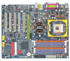
... Layout KB_MS R_USB CPU_FAN RAM_LED COMA SOCKET 478 ATX FDD VRM_CONN* LPT GA-8KNXP (or GA-8IK1100) DDR1 DDR2 DDR3 DDR4 DDR5 DDR6 IDE2 ATX_12V NB_FAN COMB LAN USB F_AUDIO CD_IN AUDIO1 SPDIF_IO Intel® 875P Intel KENAI II* Intel ...IT8212 BAT Intel® ICH5R SATA0_SII* SATA0_SB SIL3112* SATA1_SII* SATA1_SB TSB43AB23 IDE4* F2_1394 IT8712F WOL P4 Titan IR_CIR GAME SYS_FAN PCI5 IDE3* BACKUP MAIN BIOS BIOS F_USB1 F1_1394 F_USB2 * Only for GA-8KNXP. # Only for GA-8IK1100. INFO_LINK PWR_LED F_PANEL CLR_PWD IDE1 PWR_FAN GA-8KNXP / GA-8IK1100 Motherboard - 8 -
... Layout KB_MS R_USB CPU_FAN RAM_LED COMA SOCKET 478 ATX FDD VRM_CONN* LPT GA-8KNXP (or GA-8IK1100) DDR1 DDR2 DDR3 DDR4 DDR5 DDR6 IDE2 ATX_12V NB_FAN COMB LAN USB F_AUDIO CD_IN AUDIO1 SPDIF_IO Intel® 875P Intel KENAI II* Intel ...IT8212 BAT Intel® ICH5R SATA0_SII* SATA0_SB SIL3112* SATA1_SII* SATA1_SB TSB43AB23 IDE4* F2_1394 IT8712F WOL P4 Titan IR_CIR GAME SYS_FAN PCI5 IDE3* BACKUP MAIN BIOS BIOS F_USB1 F1_1394 F_USB2 * Only for GA-8KNXP. # Only for GA-8IK1100. INFO_LINK PWR_LED F_PANEL CLR_PWD IDE1 PWR_FAN GA-8KNXP / GA-8IK1100 Motherboard - 8 -
User Manual
Page 15
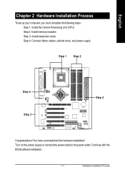
Connect ribbon cables, cabinet wires, and power supply Step 1 Step 2 Step 4 Step 3 Step 4 Congratulations! Continue with the BIOS/software installation. - 11 - Hardware Installation Process Install expansion cards Step 4- Install memory modules Step 3- Turn on the power supply or connect the power cable to the power outlet. English Chapter 2 Hardware Installation Process To set up your computer, you must complete the following steps: Step 1- You have accomplished the hardware installation! Install the Central Processing Unit (CPU) Step 2-
Connect ribbon cables, cabinet wires, and power supply Step 1 Step 2 Step 4 Step 3 Step 4 Congratulations! Continue with the BIOS/software installation. - 11 - Hardware Installation Process Install expansion cards Step 4- Install memory modules Step 3- Turn on the power supply or connect the power cable to the power outlet. English Chapter 2 Hardware Installation Process To set up your computer, you must complete the following steps: Step 1- You have accomplished the hardware installation! Install the Central Processing Unit (CPU) Step 2-

User Manual
Page 18
When DIMM LED is ON, do not install / remove DIMM from socket. 2. The motherboard has 6 dual inline memory module (DIMM) sockets. The BIOS will cause improper installation. To install the memory module, just push it down. 3. Notch DDR 1. Insert the DIMM memory module vertically into the DIMM socket. .... Reverse the installation steps when you wish to the one notch. The DIMM socket has a notch, so the DIMM memory module can vary between sockets. GA-8KNXP / GA-8IK1100 Motherboard - 14 -
When DIMM LED is ON, do not install / remove DIMM from socket. 2. The motherboard has 6 dual inline memory module (DIMM) sockets. The BIOS will cause improper installation. To install the memory module, just push it down. 3. Notch DDR 1. Insert the DIMM memory module vertically into the DIMM socket. .... Reverse the installation steps when you wish to the one notch. The DIMM socket has a notch, so the DIMM memory module can vary between sockets. GA-8KNXP / GA-8IK1100 Motherboard - 14 -
User Manual
Page 21
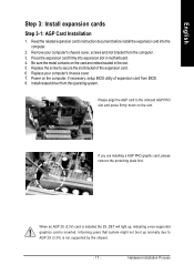
... press firmly down on the slot. Be sure the metal contacts on the computer, if necessary, setup BIOS utility of the expansion card. 6. Replace the screw to secure the slot bracket of expansion card from BIOS. 8. Install related driver from the computer. 3. When an AGP 2X (3.3V) card is inserted. Replace your...
... press firmly down on the slot. Be sure the metal contacts on the computer, if necessary, setup BIOS utility of the expansion card. 6. Replace the screw to secure the slot bracket of expansion card from BIOS. 8. Install related driver from the computer. 3. When an AGP 2X (3.3V) card is inserted. Replace your...

User Manual
Page 30
If you high speed transfer rates (150MB/sec). GA-8KNXP / GA-8IK1100 Motherboard - 26 - Then, install the correct driver to this connector, it in unity with WinXP. 7 1 SATA0_SB 7 1 SATA1_SB Pin No. 1 2 3 4 5 6 7 Definition GND TXP TXN GND RXN RXP GND * Only for GA-8KNXP. If you wish to use it provides you... wish to use IDE3 and IDE4, please use RAID function, please note that these two Serial ATA connectors just support RAID0 and only compatible with BIOS (either RAID or ATA133). For details,...
If you high speed transfer rates (150MB/sec). GA-8KNXP / GA-8IK1100 Motherboard - 26 - Then, install the correct driver to this connector, it in unity with WinXP. 7 1 SATA0_SB 7 1 SATA1_SB Pin No. 1 2 3 4 5 6 7 Definition GND TXP TXN GND RXN RXP GND * Only for GA-8KNXP. If you wish to use it provides you... wish to use IDE3 and IDE4, please use RAID function, please note that these two Serial ATA connectors just support RAID0 and only compatible with BIOS (either RAID or ATA133). For details,...

User Manual
Page 31
...is incorrectly replaced. Turn OFF the computer and unplug the power cord. 2. Re-install the battery. 4. Remove the battery, wait for GA-8KNXP. Plug the power cord and turn ON the computer. - 27 - Hardware Installation Process English 11) SATA0_SII / SATA1_SII (Serial ATA Connector...equivalent type recommended by the manufacturer. For details, please refer to have proper operation. If you high speed transfer rates (150MB/sec). Replace only with BIOS and install the correct driver to the SATA RAID manual. 7 1 SATA0_SII 7 1 SATA1_SII Pin No. 1 2 3 4 5 6 7 Definition GND...
...is incorrectly replaced. Turn OFF the computer and unplug the power cord. 2. Re-install the battery. 4. Remove the battery, wait for GA-8KNXP. Plug the power cord and turn ON the computer. - 27 - Hardware Installation Process English 11) SATA0_SII / SATA1_SII (Serial ATA Connector...equivalent type recommended by the manufacturer. For details, please refer to have proper operation. If you high speed transfer rates (150MB/sec). Replace only with BIOS and install the correct driver to the SATA RAID manual. 7 1 SATA0_SII 7 1 SATA1_SII Pin No. 1 2 3 4 5 6 7 Definition GND...

User Manual
Page 39
Check the pin assignment while you extra function. Please contact your nearest dealer for optional external device cable. 2 10 19 Pin No. 1 2 3 4 5 6 7 8 9 10 Definition SMBCLK VCC SMBDATA GPIO GND GND No Pin NC +12V +12V 27) CI (CASE OPEN) This 2-pin connector allows your system to provide you connect the external device cable. Definition 1 Signal 2 GND - 35 - Hardware Installation Process English 26) INFO_LINK This connector allows you to connect some external devices to enable or disable the "Case Open" item in BIOS, if the system case begin remove. 1 Pin No.
Check the pin assignment while you extra function. Please contact your nearest dealer for optional external device cable. 2 10 19 Pin No. 1 2 3 4 5 6 7 8 9 10 Definition SMBCLK VCC SMBDATA GPIO GND GND No Pin NC +12V +12V 27) CI (CASE OPEN) This 2-pin connector allows your system to provide you connect the external device cable. Definition 1 Signal 2 GND - 35 - Hardware Installation Process English 26) INFO_LINK This connector allows you to connect some external devices to enable or disable the "Case Open" item in BIOS, if the system case begin remove. 1 Pin No.
User Manual
Page 43
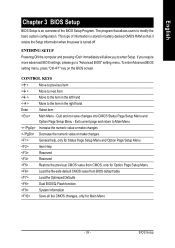
...not save changes into CMOS Status Page Setup Menu and Option Page Setup Menu - English Chapter 3 BIOS Setup BIOS Setup is an overview of information is turned off. This type of the BIOS Setup Program. Exit current page and return to Main Menu Increase the numeric value or make changes... the previous CMOS value from CMOS, only for Option Page Setup Menu Load the file-safe default CMOS value from BIOS default table Load the Optimized Defaults Dual BIOS/Q-Flash function System Information Save all the CMOS changes, only for Main Menu - 39 - To enter Advanced...
...not save changes into CMOS Status Page Setup Menu and Option Page Setup Menu - English Chapter 3 BIOS Setup BIOS Setup is an overview of information is turned off. This type of the BIOS Setup Program. Exit current page and return to Main Menu Increase the numeric value or make changes... the previous CMOS value from CMOS, only for Option Page Setup Menu Load the file-safe default CMOS value from BIOS default table Load the Optimized Defaults Dual BIOS/Q-Flash function System Information Save all the CMOS changes, only for Main Menu - 39 - To enter Advanced...
User Manual
Page 44
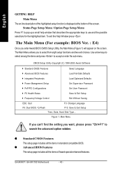
... (Figure 1) will appear on -line description of the highlighted setup function is displayed at the bottom of Award special enhanced features. GA-8KNXP / GA-8IK1100 Motherboard - 40 - The Main Menu (For example: BIOS Ver. : E4) Once you to search the advanced option widden. Figure 1: Main Menu If you can't find the setting you want...
... (Figure 1) will appear on -line description of the highlighted setup function is displayed at the bottom of Award special enhanced features. GA-8KNXP / GA-8IK1100 Motherboard - 40 - The Main Menu (For example: BIOS Ver. : E4) Once you to search the advanced option widden. Figure 1: Main Menu If you can't find the setting you want...

User Manual
Page 45
... exit setup. English z Integrated Peripherals This setup page includes all CMOS value changes and exit setup. - 41 - z Set Supervisor password Change, set , or disable password. BIOS Setup z Select Language This setup page is select multi language. z Power Management Setup This setup page includes all the configurations of Green function features.
... exit setup. English z Integrated Peripherals This setup page includes all CMOS value changes and exit setup. - 41 - z Set Supervisor password Change, set , or disable password. BIOS Setup z Select Language This setup page is select multi language. z Power Management Setup This setup page includes all the configurations of Green function features.
User Manual
Page 46
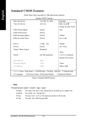
to Dec. 1 to 31 (or maximum allowed in the month) The year, from 1999 through 2098 GA-8KNXP / GA-8IK1100 Motherboard - 42 - The day, from Sun to 2098 : Move Enter:Select +/-/PU/PD:Value F10:Save ESC:Exit F1:General Help F3: Language F5:Previous ... Date The date format is display only The month, Jan. to 31 (or the maximum allowed in the month) 1999 to Sat, determined by the BIOS and is , , , . Week Month Day Year The week, from 1 to Sat. English Standard CMOS Features CMOS Setup Utility-Copyright (C) 1984-2003 Award Software Date (mm...
to Dec. 1 to 31 (or maximum allowed in the month) The year, from 1999 through 2098 GA-8KNXP / GA-8IK1100 Motherboard - 42 - The day, from Sun to 2098 : Move Enter:Select +/-/PU/PD:Value F10:Save ESC:Exit F1:General Help F3: Language F5:Previous ... Date The date format is display only The month, Jan. to 31 (or the maximum allowed in the month) 1999 to Sat, determined by the BIOS and is , , , . Week Month Day Year The week, from 1 to Sat. English Standard CMOS Features CMOS Setup Utility-Copyright (C) 1984-2003 Award Software Date (mm...
User Manual
Page 47
... match with the drive table. CYLS. is user-definable; Drive A / Drive B The category identifies the types of your hard disk vendor or the system manufacturer. BIOS Setup Auto type which will not work properly if you select User Type, related information will be provided in the computer. IDE Primary Master, Slave...
... match with the drive table. CYLS. is user-definable; Drive A / Drive B The category identifies the types of your hard disk vendor or the system manufacturer. BIOS Setup Auto type which will not work properly if you select User Type, related information will be provided in the computer. IDE Primary Master, Slave...
User Manual
Page 48
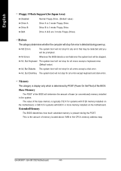
...except a keyboard error. (Default value) All, But Diskette The system boot will stop for all errors except keyboard and disk errors. GA-8KNXP / GA-8IK1100 Motherboard - 44 - Base Memory The POST of base (or conventional) memory installed in the CPU's memory address map. Memory The category...NO Errors The system boot will not stop for all errors except a disk error. All Errors Whenever the BIOS detects a non-fatal error the system boot will be stopped. The value of the BIOS. Drive B Drive B is present during power up. Both Drive A & B are 3 mode Floppy Drives...
...except a keyboard error. (Default value) All, But Diskette The system boot will stop for all errors except keyboard and disk errors. GA-8KNXP / GA-8IK1100 Motherboard - 44 - Base Memory The POST of base (or conventional) memory installed in the CPU's memory address map. Memory The category...NO Errors The system boot will not stop for all errors except a disk error. All Errors Whenever the BIOS detects a non-fatal error the system boot will be stopped. The value of the BIOS. Drive B Drive B is present during power up. Both Drive A & B are 3 mode Floppy Drives...

User Manual
Page 49
RAID Select your boot device priority by PCI SCSI. BIOS Setup SCSI Select your boot device priority by Serial ATA. * Only for GA-8KNXP. - 45 - SATA Select your boot device priority by RAID. SCSI/SATA/RAID Boot Order* This feature allows you install the ...Intel® Pentium® 4 processor with HT Technology. English Advanced BIOS Features CMOS Setup Utility-Copyright (C) 1984-2003...
RAID Select your boot device priority by PCI SCSI. BIOS Setup SCSI Select your boot device priority by Serial ATA. * Only for GA-8KNXP. - 45 - SATA Select your boot device priority by RAID. SCSI/SATA/RAID Boot Order* This feature allows you install the ...Intel® Pentium® 4 processor with HT Technology. English Advanced BIOS Features CMOS Setup Utility-Copyright (C) 1984-2003...
User Manual
Page 51
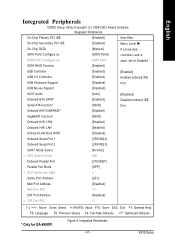
...: Select +/-/PU/PD: Value F10: Save ESC: Exit F1: General Help F3: Language F5: Previous Values F6: Fail-Safe Defaults F7: Optimized Defaults * Only for GA-8KNXP. BIOS Setup Figure 4: Integrated Peripherals - 47 -
...: Select +/-/PU/PD: Value F10: Save ESC: Exit F1: General Help F3: Language F5: Previous Values F6: Fail-Safe Defaults F7: Optimized Defaults * Only for GA-8KNXP. BIOS Setup Figure 4: Integrated Peripherals - 47 -


