Manual
Page 1
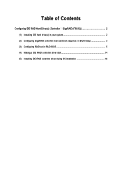
Table of Contents Configuring IDE RAID Hard Drive(s) (Controller GigaRAID (IT8212 2 (1) Installing IDE hard drive(s) in your system 2 (2) Configuring GigaRAID controller mode and boot sequence in BIOS Setup 3 (3) Configuring RAID set in RAID BIOS 5 (4) Making a IDE RAID controller driver disk 14 (5) Installing IDE RAID controller driver during OS installation 16
Table of Contents Configuring IDE RAID Hard Drive(s) (Controller GigaRAID (IT8212 2 (1) Installing IDE hard drive(s) in your system 2 (2) Configuring GigaRAID controller mode and boot sequence in BIOS Setup 3 (3) Configuring RAID set in RAID BIOS 5 (4) Making a IDE RAID controller driver disk 14 (5) Installing IDE RAID controller driver during OS installation 16
Manual
Page 2
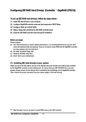
...drive. (b) An empty formatted floppy disk. (c) Windows XP/2000 setup disk. (d) Driver CD for your motherboard. (1) Installing IDE hard drive(s) in RAID BIOS. (4) Make a floppy disk containing the IDE RAID controller driver (5) Install the IDE RAID controller driver during OS installation. Before you begin Please prepare: ...follow the steps below ¤å (1) Install IDE hard drive(s) in your computer. (2) Configure GigaRAID controller mode and boot sequence in BIOS Setup. (3)* Configure RAID set in your system Attach one end of the IDE cable to the rear of the IDE hard drive and the...
...drive. (b) An empty formatted floppy disk. (c) Windows XP/2000 setup disk. (d) Driver CD for your motherboard. (1) Installing IDE hard drive(s) in RAID BIOS. (4) Make a floppy disk containing the IDE RAID controller driver (5) Install the IDE RAID controller driver during OS installation. Before you begin Please prepare: ...follow the steps below ¤å (1) Install IDE hard drive(s) in your computer. (2) Configure GigaRAID controller mode and boot sequence in BIOS Setup. (3)* Configure RAID set in your system Attach one end of the IDE cable to the rear of the IDE hard drive and the...
Manual
Page 3
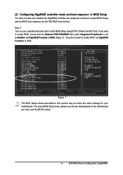
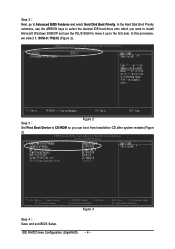
... Move Enter: Select F5: Previous Values +/-/PU/PD: Value F10: Save F6: Fail-Safe Defaults Figure 1 ESC: Exit F1: General Help F7: Optimized Defaults The BIOS Setup menus described in this section may not show the exact settings for the IDE RAID hard drive(s). The actual... Peripherals is set to Enabled and GigaRAID Function to ATA. IDE RAID Drives Configuration (GigaRAID) (2) Configuring GigaRAID controller mode and boot sequence in system BIOS Setup and set BIOS boot sequence for your computer and press Del to make sure whether the GigaRAID controller are configured correctly in...
... Move Enter: Select F5: Previous Values +/-/PU/PD: Value F10: Save F6: Fail-Safe Defaults Figure 1 ESC: Exit F1: General Help F7: Optimized Defaults The BIOS Setup menus described in this section may not show the exact settings for the IDE RAID hard drive(s). The actual... Peripherals is set to Enabled and GigaRAID Function to ATA. IDE RAID Drives Configuration (GigaRAID) (2) Configuring GigaRAID controller mode and boot sequence in system BIOS Setup and set BIOS boot sequence for your computer and press Del to make sure whether the GigaRAID controller are configured correctly in...
Manual
Page 4
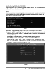
... it up to CD-ROM so you can boot from Installation CD after system restarts.(Figure 3) CMOS Setup Utility-Copyright (C) 1984-2004 Award Software Advanced BIOS Features : Move Enter: Select F5: Previous Values +/-/PU/PD: Value F10: Save F6: Fail-Safe Defaults Figure 3 ESC: Exit F1: General Help F7: Optimized Defaults...
... it up to CD-ROM so you can boot from Installation CD after system restarts.(Figure 3) CMOS Setup Utility-Copyright (C) 1984-2004 Award Software Advanced BIOS Features : Move Enter: Select F5: Previous Values +/-/PU/PD: Value F10: Save F6: Fail-Safe Defaults Figure 3 ESC: Exit F1: General Help F7: Optimized Defaults...
Manual
Page 5
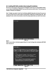
... drives to the GigaRAID controller correctly, after the Power-On Self Test (POST) memory test begins and before the operating system boot begins, the GigaRAID BIOS will guide you should see a screen similar to Figure 5 below. Navigate the GigaRAID Setup Utility: You can use Number keys 1 to 5 to select the...the RAID Card Configuration screen. Figure 4 After entering the GigaRAID Setup Utility, you to set on the GigaRAID controller. (3) Configuring RAID set in RAID BIOS Enter the RAID setup utility to create RAID set an array and this step and proceed to Section 4 if you need.
... drives to the GigaRAID controller correctly, after the Power-On Self Test (POST) memory test begins and before the operating system boot begins, the GigaRAID BIOS will guide you should see a screen similar to Figure 5 below. Navigate the GigaRAID Setup Utility: You can use Number keys 1 to 5 to select the...the RAID Card Configuration screen. Figure 4 After entering the GigaRAID Setup Utility, you to set on the GigaRAID controller. (3) Configuring RAID set in RAID BIOS Enter the RAID setup utility to create RAID set an array and this step and proceed to Section 4 if you need.
Manual
Page 16
..., there will be a few moments of Windows XP installation. ¤å Step 1: Restart your IDE hard drive with the IDE RAID controller driver and adjusted BIOS settings, you are ready to install Windows 2000/XP onto your system to boot from the Windows 2000/XP Setup disk and press F6 as...
..., there will be a few moments of Windows XP installation. ¤å Step 1: Restart your IDE hard drive with the IDE RAID controller driver and adjusted BIOS settings, you are ready to install Windows 2000/XP onto your system to boot from the Windows 2000/XP Setup disk and press F6 as...
Manual
Page 9
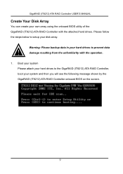
... Your Disk Array You can create your system and then you will see the following message shown by the GigaRAID (IT8212) ATA RAID Controller onboard BIOS on the screen. 9 Warning: Please backup data in your disk array. Please follow the steps below to setup your hard drives to the GigaRAID (IT8212...
... Your Disk Array You can create your system and then you will see the following message shown by the GigaRAID (IT8212) ATA RAID Controller onboard BIOS on the screen. 9 Warning: Please backup data in your disk array. Please follow the steps below to setup your hard drives to the GigaRAID (IT8212...
Manual
Page 10
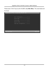
The screen below will be shown. 10 GigaRAID (IT8212) ATA RAID Controller USER'S MANUAL Please press "Ctrl-G" keys to enter the BIOS utility Main Menu.
The screen below will be shown. 10 GigaRAID (IT8212) ATA RAID Controller USER'S MANUAL Please press "Ctrl-G" keys to enter the BIOS utility Main Menu.
Manual
Page 14
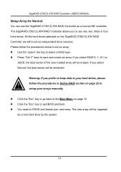
..." key to go back to save and create an array. follow the procedures below to set an array: Use the "space" bar key to quit BIOS and boot. You need to setup your new array. The GigaRAID (IT8212) ATA RAID Controller allows you select Normal, the boot sector will be remained...
..." key to go back to save and create an array. follow the procedures below to set an array: Use the "space" bar key to quit BIOS and boot. You need to setup your new array. The GigaRAID (IT8212) ATA RAID Controller allows you select Normal, the boot sector will be remained...
Manual
Page 15
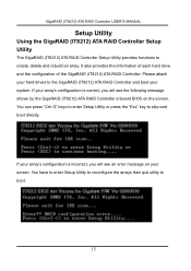
If your array's configuration is incorrect, you will see the following message shown by the GigaRAID (IT8212) ATA RAID Controller onboard BIOS on your screen. You can press "Ctrl-G" keys to enter Setup Utility or press the "Esc" key to boot. 15 You have to enter Setup ...
If your array's configuration is incorrect, you will see the following message shown by the GigaRAID (IT8212) ATA RAID Controller onboard BIOS on your screen. You can press "Ctrl-G" keys to enter Setup Utility or press the "Esc" key to boot. 15 You have to enter Setup ...

Manual
Page 88
Q: What if R1 and R0+1 just create RAID but don't Rebuild right away? A: This situation may happen to be put in the BIOS. 2. Q: Is CD ROM able to some HDs. A: It's not necessary. A: Please set booting device to Array0 and set as SCSI boot in different channels to ...
Q: What if R1 and R0+1 just create RAID but don't Rebuild right away? A: This situation may happen to be put in the BIOS. 2. Q: Is CD ROM able to some HDs. A: It's not necessary. A: Please set booting device to Array0 and set as SCSI boot in different channels to ...
Manual
Page 4
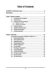
... 1-4 Installation of Memory 14 1-5 Installation of Expansion Cards 16 1-6 I/O Back Panel Introduction 17 1-7 Connectors Introduction 18 Chapter 2 BIOS Setup 29 The Main Menu (For example: GA-8I945PL-G / BIOS Ver.: F1 30 2-1 Standard CMOS Features 32 2-2 Advanced BIOS Features 35 2-3 IntegratedPeripherals 37 2-4 Power Management Setup 40 2-5 PnP/PCI Configurations 42 2-6 PC Health Status 43 2-7 MB Intelligent...
... 1-4 Installation of Memory 14 1-5 Installation of Expansion Cards 16 1-6 I/O Back Panel Introduction 17 1-7 Connectors Introduction 18 Chapter 2 BIOS Setup 29 The Main Menu (For example: GA-8I945PL-G / BIOS Ver.: F1 30 2-1 Standard CMOS Features 32 2-2 Advanced BIOS Features 35 2-3 IntegratedPeripherals 37 2-4 Power Management Setup 40 2-5 PnP/PCI Configurations 42 2-6 PC Health Status 43 2-7 MB Intelligent...

Manual
Page 5
Channel Audio Function Introduction 69 4-2 Troubleshooting 73 - 5 - Chapter 3 Install Drivers 51 3-1 Install Chipset Drivers 51 3-2 SoftwareApplications 52 3-3 Driver CD Information 52 3-4 Hardware Information 53 3-5 Contact Us ...53 Chapter 4 Appendix 55 4-1 Unique Software Utilities 55 4-1-1 EasyTune 5 Introduction 56 4-1-2 Xpress Recovery2 Introduction 57 4-1-3 Flash BIOS Method Introduction 60 4-1-4 2- / 4- / 6- / 8-
Channel Audio Function Introduction 69 4-2 Troubleshooting 73 - 5 - Chapter 3 Install Drivers 51 3-1 Install Chipset Drivers 51 3-2 SoftwareApplications 52 3-3 Driver CD Information 52 3-4 Hardware Information 53 3-5 Contact Us ...53 Chapter 4 Appendix 55 4-1 Unique Software Utilities 55 4-1-1 EasyTune 5 Introduction 56 4-1-2 Xpress Recovery2 Introduction 57 4-1-3 Flash BIOS Method Introduction 60 4-1-4 2- / 4- / 6- / 8-
Manual
Page 6
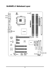
GA-8I945PL-G Motherboard Layout KB_MS COAXIAL OPTICAL ATX_12V LGA775 CPU_FAN ATX FDD LPT GA-8I945PL-G COMA USB LAN USB AUDIO1 AUDIO2 F_AUDIO Intel 945PL Broadcom 5789 PCIE_16 PCIE_1 CD_IN PCIE_2 BIOS CODEC PCI1 IT8712 PCI2 PCI3 RF_ID F_USB GREEN_USB CI SPDIF_I ICH7 DDRII1 DDRII2 DDRII3 DDRII4 IDE1 IDE3 IDE2 SATAII0 SATAII2 IT8212 SATAII1 SATAII3 SYS_FAN BAT PWR_LED F_PANEL CLR_CMOS - 6 -
GA-8I945PL-G Motherboard Layout KB_MS COAXIAL OPTICAL ATX_12V LGA775 CPU_FAN ATX FDD LPT GA-8I945PL-G COMA USB LAN USB AUDIO1 AUDIO2 F_AUDIO Intel 945PL Broadcom 5789 PCIE_16 PCIE_1 CD_IN PCIE_2 BIOS CODEC PCI1 IT8712 PCI2 PCI3 RF_ID F_USB GREEN_USB CI SPDIF_I ICH7 DDRII1 DDRII2 DDRII3 DDRII4 IDE1 IDE3 IDE2 SATAII0 SATAII2 IT8212 SATAII1 SATAII3 SYS_FAN BAT PWR_LED F_PANEL CLR_CMOS - 6 -
Manual
Page 7
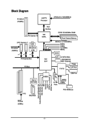
... Bus IT8212 IDE RAID Host Interface Intel 945PL Intel ICH7 DDRII 533/400MHz DIMM Dual Channel Memory MCHCLK (133/200MHz) 66MHz 33MHz 14.318MHz 48MHz BIOS 4 SATA 3Gb/s ATA33/66/100 IDE1 Channels Floppy IT 8712 LPT Port CODEC COM Port 8 USB Ports 24MHz 33MHz 3 PCI IDE2/IDE3 PS/2 KB/Mouse...
... Bus IT8212 IDE RAID Host Interface Intel 945PL Intel ICH7 DDRII 533/400MHz DIMM Dual Channel Memory MCHCLK (133/200MHz) 66MHz 33MHz 14.318MHz 48MHz BIOS 4 SATA 3Gb/s ATA33/66/100 IDE1 Channels Floppy IT 8712 LPT Port CODEC COM Port 8 USB Ports 24MHz 33MHz 3 PCI IDE2/IDE3 PS/2 KB/Mouse...
Manual
Page 11
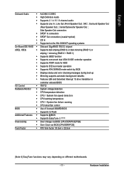
... Š Supports ATAPI mode for HDD Š Supports IDE bus master operation Š Supports ATA133/RAID mode switch by BIOS Š Displays status and error checking messages during boot-up Š Mirroring supports automatic background rebuilds Š Features LBA ...and Extended Interrupt 13 drive translation in controller onboard BIOS I/O Control Š IT8712 Hardware Monitor Š System voltage detection Š CPU temperature detection Š CPU / System fan speed ...
... Š Supports ATAPI mode for HDD Š Supports IDE bus master operation Š Supports ATA133/RAID mode switch by BIOS Š Displays status and error checking messages during boot-up Š Mirroring supports automatic background rebuilds Š Features LBA ...and Extended Interrupt 13 drive translation in controller onboard BIOS I/O Control Š IT8712 Hardware Monitor Š System voltage detection Š CPU temperature detection Š CPU / System fan speed ...
Manual
Page 12
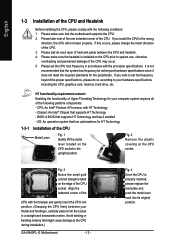
... sure that might cause damage to your thumb and forefinger, carefully place it into the socket in a straight and downwards motion. BIOS: A BIOS that supports HT Technology - Fig. 2 Remove the plastic covering on the CPU prior to system use, otherwise overheating and permanent ...174; Pentium 4 Processor with HT Technology - Please set beyond the proper specifications, please do so according to the CPU during installation.) GA-8I945PL-G Motherboard - 12 - Align the indented corner of the CPU with the triangle and gently insert the CPU into its original position. English...
... sure that might cause damage to your thumb and forefinger, carefully place it into the socket in a straight and downwards motion. BIOS: A BIOS that supports HT Technology - Fig. 2 Remove the plastic covering on the CPU prior to system use, otherwise overheating and permanent ...174; Pentium 4 Processor with HT Technology - Please set beyond the proper specifications, please do so according to the CPU during installation.) GA-8I945PL-G Motherboard - 12 - Align the indented corner of the CPU with the triangle and gently insert the CPU into its original position. English...
Manual
Page 14
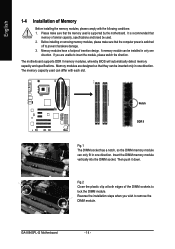
...direction. The memory capacity used can be inserted only in one direction. Insert the DIMM memory module vertically into the DIMM socket. GA-8I945PL-G Motherboard - 14 - It is recommended that the memory used . 2. Before installing or removing memory modules, please make sure ... be installed in only one direction. Memory modules have a foolproof insertion design. The motherboard supports DDR II memory modules, whereby BIOS will automatically detect memory capacity and specifications. Then push it down. A memory module can differ with the following conditions: 1....
...direction. The memory capacity used can be inserted only in one direction. Insert the DIMM memory module vertically into the DIMM socket. GA-8I945PL-G Motherboard - 14 - It is recommended that the memory used . 2. Before installing or removing memory modules, please make sure ... be installed in only one direction. Memory modules have a foolproof insertion design. The motherboard supports DDR II memory modules, whereby BIOS will automatically detect memory capacity and specifications. Then push it down. A memory module can differ with the following conditions: 1....
Manual
Page 16
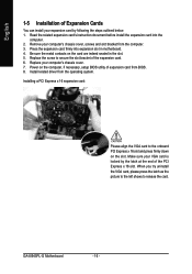
...card: Please align the VGA card to the onboard PCI Express x 16 slot and press firmly down on the card are indeed seated in motherboard. 4. GA-8I945PL-G Motherboard - 16 - English 1-5 Installation of the PCI Express x 16 slot. When you try uninstall the VGA card, please press the latch as... the picture to the left shows to secure the slot bracket of expansion card from BIOS. 8. Remove your computer's chassis cover, screws and slot bracket from the operating system. Replace the screw to release the card. Install ...
...card: Please align the VGA card to the onboard PCI Express x 16 slot and press firmly down on the card are indeed seated in motherboard. 4. GA-8I945PL-G Motherboard - 16 - English 1-5 Installation of the PCI Express x 16 slot. When you try uninstall the VGA card, please press the latch as... the picture to the left shows to secure the slot bracket of expansion card from BIOS. 8. Remove your computer's chassis cover, screws and slot bracket from the operating system. Replace the screw to release the card. Install ...
Manual
Page 21
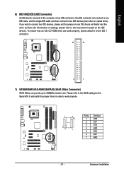
... optical drive). To ensure that an IDE CD-ROM drive can provide up to the instructions located on the IDE device). Please refer to the BIOS setting for information on one IDE cable, and the single IDE cable can connect to one IDE device as Master and the other as Slave...
... optical drive). To ensure that an IDE CD-ROM drive can provide up to the instructions located on the IDE device). Please refer to the BIOS setting for information on one IDE cable, and the single IDE cable can connect to one IDE device as Master and the other as Slave...


