Manual
Page 1
GA-8I945P Pro/ GA-8I945P-G Intel® Pentium® D / Pentium® 4 LGA775 Processor Motherboard User's Manual Rev. 1005 12ME-8I945PP-1005 * The WEEE marking on the product indicates this product must not be disposed of with user's other household waste and must be handed over to a designated collection point for the recycling of waste electrical and electronic equipment!! * The WEEE marking applies only in European Union's member states.
GA-8I945P Pro/ GA-8I945P-G Intel® Pentium® D / Pentium® 4 LGA775 Processor Motherboard User's Manual Rev. 1005 12ME-8I945PP-1005 * The WEEE marking on the product indicates this product must not be disposed of with user's other household waste and must be handed over to a designated collection point for the recycling of waste electrical and electronic equipment!! * The WEEE marking applies only in European Union's member states.
Manual
Page 2
Motherboard GA-8I945P Pro/GA-8I945P-G Apr. 18, 2005 Motherboard GA-8I945P Pro/GA-8I945P-G Apr. 18, 2005
Motherboard GA-8I945P Pro/GA-8I945P-G Apr. 18, 2005 Motherboard GA-8I945P Pro/GA-8I945P-G Apr. 18, 2005
Manual
Page 4
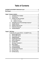
Table of Contents GA-8I945P Pro/GA-8I945P-G Motherboard Layout 6 Block Diagram ...7 Chapter 1 Hardware Installation 9 1-1 Considerations Prior to Installation 9 1-2 Feature Summary 10 1-3 Installation of the CPU and Heatsink 12 1-3-1... of Expansion Cards 16 1-7 I/O Back Panel Introduction 17 1-8 Connectors Introduction 18 Chapter 2 BIOS Setup 29 The Main Menu (For example: BIOS Ver. : GA-8I945P Pro F2a 30 2-1 Standard CMOS Features 32 2-2 Advanced BIOS Features 34 2-3 IntegratedPeripherals 36 2-4 Power Management Setup 39 2-5 PnP/PCI Configurations 41 2-6 PC Health Status...
Table of Contents GA-8I945P Pro/GA-8I945P-G Motherboard Layout 6 Block Diagram ...7 Chapter 1 Hardware Installation 9 1-1 Considerations Prior to Installation 9 1-2 Feature Summary 10 1-3 Installation of the CPU and Heatsink 12 1-3-1... of Expansion Cards 16 1-7 I/O Back Panel Introduction 17 1-8 Connectors Introduction 18 Chapter 2 BIOS Setup 29 The Main Menu (For example: BIOS Ver. : GA-8I945P Pro F2a 30 2-1 Standard CMOS Features 32 2-2 Advanced BIOS Features 34 2-3 IntegratedPeripherals 36 2-4 Power Management Setup 39 2-5 PnP/PCI Configurations 41 2-6 PC Health Status...
Manual
Page 7
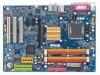
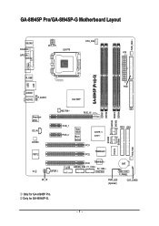
GA-8I945P Pro/GA-8I945P-G Motherboard Layout KB_MS ATX_12V CPU_FAN COAXIAL LGA775 ATX OPTICAL PWR_FAN LPT LAN COMA GA-8I945P (Pro)(-G) R_USB USB FDD AUDIO1 AUDIO2 F_AUDIO Intel 945P Broadcom 5789 CD_IN CODEC IT8712 NB_FAN PCIE_16 PCIE_1 PCIE_2 Main BIOS Back BIOS ICH7R / ICH7 PCI1 TSB82AA2 PCI2 SATAII0 IT8212 SATAII1 DDRII1 DDRII2 SATAII2 SATAII3 DDRII3 DDRII4 IDE1 IDE3 IDE2 SYS_FAN PCI3 TSB81BA3 BAT F_USB GREEN_USB F1_1394 F2_1394 CI SPDIF_I F_PANEL RF_ID PWR_LED (Optional) CLR_CMOS Only for GA-8I945P-G. - 7 - Only for GA-8I945P Pro.
GA-8I945P Pro/GA-8I945P-G Motherboard Layout KB_MS ATX_12V CPU_FAN COAXIAL LGA775 ATX OPTICAL PWR_FAN LPT LAN COMA GA-8I945P (Pro)(-G) R_USB USB FDD AUDIO1 AUDIO2 F_AUDIO Intel 945P Broadcom 5789 CD_IN CODEC IT8712 NB_FAN PCIE_16 PCIE_1 PCIE_2 Main BIOS Back BIOS ICH7R / ICH7 PCI1 TSB82AA2 PCI2 SATAII0 IT8212 SATAII1 DDRII1 DDRII2 SATAII2 SATAII3 DDRII3 DDRII4 IDE1 IDE3 IDE2 SYS_FAN PCI3 TSB81BA3 BAT F_USB GREEN_USB F1_1394 F2_1394 CI SPDIF_I F_PANEL RF_ID PWR_LED (Optional) CLR_CMOS Only for GA-8I945P-G. - 7 - Only for GA-8I945P Pro.
Manual
Page 8
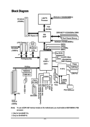
... Speaker Out Side Speaker Out MIC Line-Out Line-In SPDIF In SPDIF Out PCICLK (33MHz) (Note) To use a DDRII 667 memory module on the motherboard, you must install an 800/1066MHz FSB processor . Only for GA-8I945P Pro. Only for GA-8I945P-G. - 8 -
... Speaker Out Side Speaker Out MIC Line-Out Line-In SPDIF In SPDIF Out PCICLK (33MHz) (Note) To use a DDRII 667 memory module on the motherboard, you must install an 800/1066MHz FSB processor . Only for GA-8I945P Pro. Only for GA-8I945P-G. - 8 -
Manual
Page 10
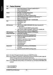
... amount of memory is reserved for system usage and therefore the actual memory size is less than the stated amount. Only for GA-8I945P Pro. GA-8I945P (Pro)(-G) Motherboard - 10 - English 1-2 Feature Summary CPU Š Š Š Chipset Š Š Š Memory &#...GIGABYTE's website. (Note 2) Due to 4GB memory) (Note 2) Supports 1.8V DDR II DIMM Supports dual channel DDR II 667(Note 3)/533/400 DIMM 1 PCI Express x 16 slot 2 PCI Express x 1 slot 3 PCI slots 1 IDE connection (UDMA 33/ATA 66/ATA 100), allows connection of 2 IDE devices(IDE1) - Only for GA-8I945P...
... amount of memory is reserved for system usage and therefore the actual memory size is less than the stated amount. Only for GA-8I945P Pro. GA-8I945P (Pro)(-G) Motherboard - 10 - English 1-2 Feature Summary CPU Š Š Š Chipset Š Š Š Memory &#...GIGABYTE's website. (Note 2) Due to 4GB memory) (Note 2) Supports 1.8V DDR II DIMM Supports dual channel DDR II 667(Note 3)/533/400 DIMM 1 PCI Express x 16 slot 2 PCI Express x 1 slot 3 PCI slots 1 IDE connection (UDMA 33/ATA 66/ATA 100), allows connection of 2 IDE devices(IDE1) - Only for GA-8I945P...
Manual
Page 12
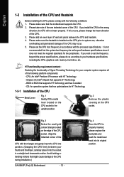
...accordance with the processor specifications. Avoid twisting or bending motions that has optimizations for the peripherals. If you wish to the CPU during installation.) GA-8I945P (Pro)(-G) Motherboard - 12 - If this occurs, please change the insert direction of the CPU. Align the indented corner of the CPU with the triangle... between your hardware specifications including the CPU, graphics card, memory, hard drive, etc. Chipset: An Intel® Chipset that the motherboard supports the CPU. 2. Fig. 3 Notice the small gold colored triangle located on the CPU socket.
...accordance with the processor specifications. Avoid twisting or bending motions that has optimizations for the peripherals. If you wish to the CPU during installation.) GA-8I945P (Pro)(-G) Motherboard - 12 - If this occurs, please change the insert direction of the CPU. Align the indented corner of the CPU with the triangle... between your hardware specifications including the CPU, graphics card, memory, hard drive, etc. Chipset: An Intel® Chipset that the motherboard supports the CPU. 2. Fig. 3 Notice the small gold colored triangle located on the CPU socket.
Manual
Page 14
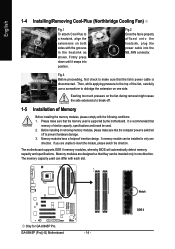
...Exerting too much pressure on the fan during removal might cause the side extensions to break-off to prevent hardware damage. 3. Only for GA-8I945P Pro. Then, while applying pressure to dislodge the extension on both sides with the grooves in one direction. Before installing or removing memory modules...in the heatsink as shown. Memory modules have a foolproof insertion design. A memory module can be installed in only one direction. GA-8I945P (Pro)(-G) Motherboard - 14 - Fig.3 Before proceeding, first check to insert the module, please switch the direction.
...Exerting too much pressure on the fan during removal might cause the side extensions to break-off to prevent hardware damage. 3. Only for GA-8I945P Pro. Then, while applying pressure to dislodge the extension on both sides with the grooves in one direction. Before installing or removing memory modules...in the heatsink as shown. Memory modules have a foolproof insertion design. A memory module can be installed in only one direction. GA-8I945P (Pro)(-G) Motherboard - 14 - Fig.3 Before proceeding, first check to insert the module, please switch the direction.
Manual
Page 16
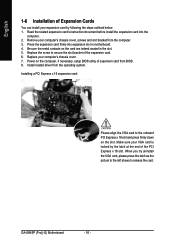
... cover, screws and slot bracket from the operating system. Replace your VGA card is locked by following the steps outlined below: 1. GA-8I945P (Pro)(-G) Motherboard - 16 - Power on the card are indeed seated in motherboard. 4. Read the related expansion card's instruction document before install the expansion card into expansion slot in the slot. 5. Make sure...
... cover, screws and slot bracket from the operating system. Replace your VGA card is locked by following the steps outlined below: 1. GA-8I945P (Pro)(-G) Motherboard - 16 - Power on the card are indeed seated in motherboard. 4. Read the related expansion card's instruction document before install the expansion card into expansion slot in the slot. 5. Make sure...
Manual
Page 18
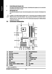
... 15 16 20 11 12 1) ATX_12V 2) ATX (Power Connector) 3) CPU_FAN 4) SYS_FAN 5) PWR_FAN 6) NB_FAN 7) FDD 8) IDE1/IDE2/IDE3 9) SATAII0 / SATAII1 / SATAII2 / SATAII3 10) F_AUDIO Only for GA-8I945P Pro. GA-8I945P (Pro)(-G) Motherboard 11) 12) 13) 14) 15) 16) 17) 18) 19) 20) - 18 - Surround side speakers can be connected to Side Speaker Out jack. English Center/Subwoofer...
... 15 16 20 11 12 1) ATX_12V 2) ATX (Power Connector) 3) CPU_FAN 4) SYS_FAN 5) PWR_FAN 6) NB_FAN 7) FDD 8) IDE1/IDE2/IDE3 9) SATAII0 / SATAII1 / SATAII2 / SATAII3 10) F_AUDIO Only for GA-8I945P Pro. GA-8I945P (Pro)(-G) Motherboard 11) 12) 13) 14) 15) 16) 17) 18) 19) 20) - 18 - Surround side speakers can be connected to Side Speaker Out jack. English Center/Subwoofer...

Manual
Page 20
... overheating and failure. 1 CPU_FAN 1 SYS_FAN/ PWR_FAN Pin No. 1 2 3 4 Definition GND +12V Sense Speed Control (Only for GA-8I945P Pro. Please remember to connect the power to the CPU fan to prevent system overheating and failure. Caution! GA-8I945P (Pro)(-G) Motherboard - 20 - English 3/4/5) CPU_FAN / SYS_FAN / PWR_FAN (Cooler Fan Power Connector) The cooler fan power connector supplies a +12V power...
... overheating and failure. 1 CPU_FAN 1 SYS_FAN/ PWR_FAN Pin No. 1 2 3 4 Definition GND +12V Sense Speed Control (Only for GA-8I945P Pro. Please remember to connect the power to the CPU fan to prevent system overheating and failure. Caution! GA-8I945P (Pro)(-G) Motherboard - 20 - English 3/4/5) CPU_FAN / SYS_FAN / PWR_FAN (Cooler Fan Power Connector) The cooler fan power connector supplies a +12V power...
Manual
Page 22
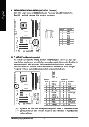
... 2 GND 3 MIC Power 4 NC 5 Line Out (R) 6 NC 7 NC 8 No Pin 9 Line Out (L) 10 NC By default, the audio driver is configured to 300MB/s transfer rate. GA-8I945P (Pro)(-G) Motherboard - 22 - English 9) SATAII0/SATAII1/SATAII2/SATAII3 (SATA 3Gb/s Connector) SATA 3Gb/s can provide up to support HD Audio.
... 2 GND 3 MIC Power 4 NC 5 Line Out (R) 6 NC 7 NC 8 No Pin 9 Line Out (L) 10 NC By default, the audio driver is configured to 300MB/s transfer rate. GA-8I945P (Pro)(-G) Motherboard - 22 - English 9) SATAII0/SATAII1/SATAII2/SATAII3 (SATA 3Gb/s Connector) SATA 3Gb/s can provide up to support HD Audio.
Manual
Page 24
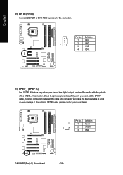
... while you connect the SPDIF cable, incorrect connection between the cable and connector will make the device unable to the connector. Definition 1 Power 1 2 SPDIFI 3 GND GA-8I945P (Pro)(-G) Motherboard - 24 - Be careful with the polarity of the SPDIF_IN connector. Definition 1 CD-L 1 2 GND 3 GND 4 CD-R 14) SPDIF_I (SPDIF In) Use SPDIF IN feature only when...
... while you connect the SPDIF cable, incorrect connection between the cable and connector will make the device unable to the connector. Definition 1 Power 1 2 SPDIFI 3 GND GA-8I945P (Pro)(-G) Motherboard - 24 - Be careful with the polarity of the SPDIF_IN connector. Definition 1 CD-L 1 2 GND 3 GND 4 CD-R 14) SPDIF_I (SPDIF In) Use SPDIF IN feature only when...
Manual
Page 26
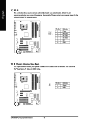
... 1 Power 1 2 RFID_RI- 3 RF_TXD 4 RF_RXD 5 NC 6 GND 18) CI (Chassis Intrusion, Case Open) This 2-pin connector allows your nearest dealer for the optional GIGABYTE external device. Definition 1 1 Signal 2 GND GA-8I945P (Pro)(-G) Motherboard - 26 - You can check the "Case Opened" status in BIOS Setup. English 17) RF_ID This connector allows you connect the external device cable...
... 1 Power 1 2 RFID_RI- 3 RF_TXD 4 RF_RXD 5 NC 6 GND 18) CI (Chassis Intrusion, Case Open) This 2-pin connector allows your nearest dealer for the optional GIGABYTE external device. Definition 1 1 Signal 2 GND GA-8I945P (Pro)(-G) Motherboard - 26 - You can check the "Case Opened" status in BIOS Setup. English 17) RF_ID This connector allows you connect the external device cable...

Manual
Page 28
English GA-8I945P (Pro)(-G) Motherboard - 28 -
English GA-8I945P (Pro)(-G) Motherboard - 28 -
Manual
Page 29
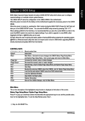
...the first time, it is recommended that you to select item Select Item Main Menu - Exit current page and return to a new BIOS, either Gigabyte's Q-Flash or @BIOS utility can enter the BIOS setup screen by pressing "Ctrl + F1". BIOS Setup English Chapter 2 BIOS Setup BIOS (Basic... Save all the CMOS changes, only for GA-8I945P Pro. - 29 - You can be reset to its original settings. Q-Flash allows the user to quickly and easily update or backup BIOS without entering the operating system. @BIOS is turned on the motherboard supplies the necessary power to activate certain system...
...the first time, it is recommended that you to select item Select Item Main Menu - Exit current page and return to a new BIOS, either Gigabyte's Q-Flash or @BIOS utility can enter the BIOS setup screen by pressing "Ctrl + F1". BIOS Setup English Chapter 2 BIOS Setup BIOS (Basic... Save all the CMOS changes, only for GA-8I945P Pro. - 29 - You can be reset to its original settings. Q-Flash allows the user to quickly and easily update or backup BIOS without entering the operating system. @BIOS is turned on the motherboard supplies the necessary power to activate certain system...
Manual
Page 30
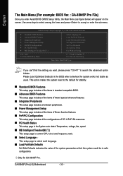
... figure below) will appear on the screen. If you can't find the setting you enter Award BIOS CMOS Setup Utility, the Main Menu (as usual. GA-8I945P (Pro)(-G) Motherboard - 30 - Please Load Optimized Defaults in safe configuration. CMOS Setup Utility-Copyright (C) 1984-2005 Award Software ` Standard CMOS Features ` Advanced BIOS Features ` Integrated Peripherals... keys to select among the items and press to accept or enter the sub-menu. English The Main Menu (For example: BIOS Ver. : GA-8I945P Pro F2a) Once you want, please press "Ctrl+F1" to search the advanced option hidden.
... figure below) will appear on the screen. If you can't find the setting you enter Award BIOS CMOS Setup Utility, the Main Menu (as usual. GA-8I945P (Pro)(-G) Motherboard - 30 - Please Load Optimized Defaults in safe configuration. CMOS Setup Utility-Copyright (C) 1984-2005 Award Software ` Standard CMOS Features ` Advanced BIOS Features ` Integrated Peripherals... keys to select among the items and press to accept or enter the sub-menu. English The Main Menu (For example: BIOS Ver. : GA-8I945P Pro F2a) Once you want, please press "Ctrl+F1" to search the advanced option hidden.
Manual
Page 32
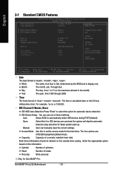
... the maximum allowed in . The time is display only The month, Jan. You can manually input the correct settings Access Mode Use this option for GA-8I945P Pro. GA-8I945P (Pro)(-G) Motherboard - 32 -
... the maximum allowed in . The time is display only The month, Jan. You can manually input the correct settings Access Mode Use this option for GA-8I945P Pro. GA-8I945P (Pro)(-G) Motherboard - 32 -
Manual
Page 34
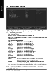
... this menu. Hard Disk CDROM Select your boot device priority by Floppy. ZIP USB-FDD Select your boot device priority by LAN. GA-8I945P (Pro)(-G) Motherboard - 34 - to move it up when you install the Intel® Pentium® 4 processor with HT Technology. Only for onboard...(or add-on cards) SCSI, RAID, etc. Hard Disk Boot Priority Select boot sequence for GA-8I945P Pro. First / Second / Third Boot Device Floppy Select your boot device priority by Disabled. Select your boot device priority by ZIP. ...
... this menu. Hard Disk CDROM Select your boot device priority by Floppy. ZIP USB-FDD Select your boot device priority by LAN. GA-8I945P (Pro)(-G) Motherboard - 34 - to move it up when you install the Intel® Pentium® 4 processor with HT Technology. Only for onboard...(or add-on cards) SCSI, RAID, etc. Hard Disk Boot Priority Select boot sequence for GA-8I945P Pro. First / Second / Third Boot Device Floppy Select your boot device priority by Disabled. Select your boot device priority by ZIP. ...
Manual
Page 36
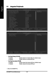
... Help F7: Optimized Defaults On-Chip Primary PCI IDE Enabled Enable onboard 1st channel IDE port. (Default value) Disabled Disable onboard 1st channel IDE port. GA-8I945P (Pro)(-G) Motherboard - 36 - Only for GA-8I945P Pro.
... Help F7: Optimized Defaults On-Chip Primary PCI IDE Enabled Enable onboard 1st channel IDE port. (Default value) Disabled Disable onboard 1st channel IDE port. GA-8I945P (Pro)(-G) Motherboard - 36 - Only for GA-8I945P Pro.


