Manual
Page 2
...not want to create RAID with identical model and capacity). "*" Skip this step if you do not want to create RAID array on the motherboard. (To ensure that you use two hard drives with the GigaRAID controller, you may prepare only one hard drive. (b) An empty formatted ...floppy disk. (c) Windows XP/2000 setup disk. (d) Driver CD for your motherboard. (1) Installing IDE hard drive(s) in RAID BIOS. (4) Make a floppy disk containing the IDE RAID controller driver (5) Install the IDE RAID controller driver ...
...not want to create RAID with identical model and capacity). "*" Skip this step if you do not want to create RAID array on the motherboard. (To ensure that you use two hard drives with the GigaRAID controller, you may prepare only one hard drive. (b) An empty formatted ...floppy disk. (c) Windows XP/2000 setup disk. (d) Driver CD for your motherboard. (1) Installing IDE hard drive(s) in RAID BIOS. (4) Make a floppy disk containing the IDE RAID controller driver (5) Install the IDE RAID controller driver ...
Manual
Page 3
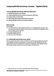
Step 1: Turn on the motherboard you want to create RAID, set to Enabled and GigaRAID Function to RAID (Figure 1). If you have to make sure whether the GigaRAID controller are ... in system BIOS Setup and set BIOS boot sequence for your computer and press Del to ATA. If you will see shall depend on your motherboard. CMOS Setup Utility-Copyright (C) 1984-2004 Award Software Integrated Peripherals : Move Enter: Select F5: Previous Values +/-/PU/PD: Value F10: Save F6: Fail-Safe Defaults...
Step 1: Turn on the motherboard you want to create RAID, set to Enabled and GigaRAID Function to RAID (Figure 1). If you have to make sure whether the GigaRAID controller are ... in system BIOS Setup and set BIOS boot sequence for your computer and press Del to ATA. If you will see shall depend on your motherboard. CMOS Setup Utility-Copyright (C) 1984-2004 Award Software Integrated Peripherals : Move Enter: Select F5: Previous Values +/-/PU/PD: Value F10: Save F6: Fail-Safe Defaults...
Manual
Page 14
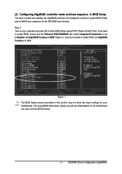
... 14 - Ác (4) Making a IDE RAID controller driver disk Åé To install Windows 2000/XP onto a hard drive on your motherboard during the Windows setup process. ¤å First of all, you need to the BootDrv folder and look for the GigaRAID controller on the GigaRAID... controller successfully, you need to copy the driver for the IDE RAID controller from the motherboard driver CD to a floppydisk. Quit the installation utility first. The installation utility will appear automatically. Step 2: Go to copy the driver...
... 14 - Ác (4) Making a IDE RAID controller driver disk Åé To install Windows 2000/XP onto a hard drive on your motherboard during the Windows setup process. ¤å First of all, you need to the BootDrv folder and look for the GigaRAID controller on the GigaRAID... controller successfully, you need to copy the driver for the IDE RAID controller from the motherboard driver CD to a floppydisk. Quit the installation utility first. The installation utility will appear automatically. Step 2: Go to copy the driver...
Manual
Page 15
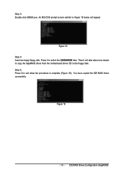
An MS-DOS prompt screen similar to select the 2)GIGARAID item. Figure 18 Step 4: Insert an empty floppy disk. You have copied the IDE RAID driver sucessfully. Press 2 to Figure 18 below will take about one minute to copy the GigaRAID driver from the motherboard driver CD to exit when the procedure is complete (Figure 19). Figure 19 - 15 - Step 5: Press 0 to the floppy disk. IDE RAID Drives Configuration (GigaRAID) Then it will appear. Step 3: Double-click MENU.exe.
An MS-DOS prompt screen similar to select the 2)GIGARAID item. Figure 18 Step 4: Insert an empty floppy disk. You have copied the IDE RAID driver sucessfully. Press 2 to Figure 18 below will take about one minute to copy the GigaRAID driver from the motherboard driver CD to exit when the procedure is complete (Figure 19). Figure 19 - 15 - Step 5: Press 0 to the floppy disk. IDE RAID Drives Configuration (GigaRAID) Then it will appear. Step 3: Double-click MENU.exe.
Manual
Page 17
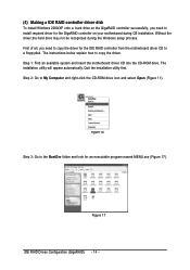
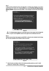
The driver installation will be found, please check the floppy disk or copy the correct GigaRAID controller driver again from the motherboard driver CD. Then it will appear. Figure 22 If a message appears saying one or some file(s) cannot be finished in the floppy disk, a controller menu ...
The driver installation will be found, please check the floppy disk or copy the correct GigaRAID controller driver again from the motherboard driver CD. Then it will appear. Figure 22 If a message appears saying one or some file(s) cannot be finished in the floppy disk, a controller menu ...
Manual
Page 72
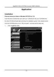
Click "GigaRAID Utility. 72 GigaRAID (IT8212) ATA RAID Controller USER'S MANUAL Application Installation Pictures below are shown in "My computer", and execute the setup.exe. 1. If not, please double click the CD-ROM device icon in Windows XP (CD ver. 2.2) Insert the driver CD-title that came with your motherboard into your CD-ROM drive, the driver CD-title will auto start and show the installation guide.
Click "GigaRAID Utility. 72 GigaRAID (IT8212) ATA RAID Controller USER'S MANUAL Application Installation Pictures below are shown in "My computer", and execute the setup.exe. 1. If not, please double click the CD-ROM device icon in Windows XP (CD ver. 2.2) Insert the driver CD-title that came with your motherboard into your CD-ROM drive, the driver CD-title will auto start and show the installation guide.

Manual
Page 1
GA-8I915P Series Intel® Pentium® 4 LGA775 Processor Motherboard User's Manual Rev. 2002 12ME-8I915PU-2002
GA-8I915P Series Intel® Pentium® 4 LGA775 Processor Motherboard User's Manual Rev. 2002 12ME-8I915PU-2002

Manual
Page 4
Table of Contents GA-8I915P (Ultra)(Pro)(-G) Motherboard Layout 6 Block Diagram ...7 Chapter 1 Hardware Installation 9 1-1 Considerations Priorto Installation 9 1-2 Feature Summary 10 1-3 Installation of the CPU and Heatsink 12 1-3-1 Installation of the CPU 12 1-3-2 Installation ...
Table of Contents GA-8I915P (Ultra)(Pro)(-G) Motherboard Layout 6 Block Diagram ...7 Chapter 1 Hardware Installation 9 1-1 Considerations Priorto Installation 9 1-2 Feature Summary 10 1-3 Installation of the CPU and Heatsink 12 1-3-1 Installation of the CPU 12 1-3-2 Installation ...

Manual
Page 6
Only for GA-8I915P Ultra. GA-8I915P (Ultra)(Pro)(-G) Motherboard Layout KB_MS SP DIF_O UT SP DIF_IN C PU _ FAN A TX_12V PWR_FA N LGA 775 GA-8I915P (Ultra)(Pro)(-G) DDR1 DDR2 DDR3 DDR4 ATX LPT COMA USB LAN USB IT8212 CLR_CMOS A U D IO 1 A U D IO 2 Marv ell 8001 I ntel 915P AZALIA_FP CD_IN C ODEC N B_ ... TS B43A B23 PCI1 IDE3 IDE1 FDD IT8712 PCI2 IDE2 F1_1 394 F_U SB 2 SYS_FAN F_PAN EL IR F_U SB 1 F2_1 394 P WR_LE D Only for GA-8I915P Pro. Only for GA-8I915P-G. - 6 -
Only for GA-8I915P Ultra. GA-8I915P (Ultra)(Pro)(-G) Motherboard Layout KB_MS SP DIF_O UT SP DIF_IN C PU _ FAN A TX_12V PWR_FA N LGA 775 GA-8I915P (Ultra)(Pro)(-G) DDR1 DDR2 DDR3 DDR4 ATX LPT COMA USB LAN USB IT8212 CLR_CMOS A U D IO 1 A U D IO 2 Marv ell 8001 I ntel 915P AZALIA_FP CD_IN C ODEC N B_ ... TS B43A B23 PCI1 IDE3 IDE1 FDD IT8712 PCI2 IDE2 F1_1 394 F_U SB 2 SYS_FAN F_PAN EL IR F_U SB 1 F2_1 394 P WR_LE D Only for GA-8I915P Pro. Only for GA-8I915P-G. - 6 -

Manual
Page 9
... 3. Damage due to be an unofficial Gigabyte product. - 9 - Damage as a result of an antistatic pad or within the computer casing. 6. To prevent damage to the motherboard, please do not remove the stickers on the motherboard. Please make sure there are uncertain about... cables and power connectors are required for warranty validation. 2. Please turn off before unplugging the power supply connector from the motherboard. When handling the motherboard, avoid touching any hardware, please first carefully read the information in the user manual. 3. Turning on an uneven surface....
... 3. Damage due to be an unofficial Gigabyte product. - 9 - Damage as a result of an antistatic pad or within the computer casing. 6. To prevent damage to the motherboard, please do not remove the stickers on the motherboard. Please make sure there are uncertain about... cables and power connectors are required for warranty validation. 2. Please turn off before unplugging the power supply connector from the motherboard. When handling the motherboard, avoid touching any hardware, please first carefully read the information in the user manual. 3. Turning on an uneven surface....

Manual
Page 10
... 2 IDE devices (IDE1) w 2 IDE connection (UDMA 33/ATA 66/ATA 100/ATA 133), compatible with CPU w GA-8I915P Series Motherboard: GA-8I915P Ultra/GA-8I915P Pro/GA-8I915P-G/GA-8I915P w Northbridge: Intel® 915P Express Chipset w Southbridge: Intel® ICH6 w 4 DDR DIMM memory slots (supports up...of memory size will instead be shown as 3.xxGB memory during system startup. Only for GA-8I915P-G. Only for GA-8I915P Ultra. GA-8I915P Series Motherboard - 10 - MIC ; Only for GA-8I915P Pro. Center/Subwoofer Speaker Out ; Back Surround Speaker Out ; English 1-2 Feature Summary CPU...
... 2 IDE devices (IDE1) w 2 IDE connection (UDMA 33/ATA 66/ATA 100/ATA 133), compatible with CPU w GA-8I915P Series Motherboard: GA-8I915P Ultra/GA-8I915P Pro/GA-8I915P-G/GA-8I915P w Northbridge: Intel® 915P Express Chipset w Southbridge: Intel® ICH6 w 4 DDR DIMM memory slots (supports up...of memory size will instead be shown as 3.xxGB memory during system startup. Only for GA-8I915P-G. Only for GA-8I915P Ultra. GA-8I915P Series Motherboard - 10 - MIC ; Only for GA-8I915P Pro. Center/Subwoofer Speaker Out ; Back Surround Speaker Out ; English 1-2 Feature Summary CPU...

Manual
Page 12
...the edge of the CPU socket. Fig. 2 Rem ov e the pl astic covering on the CPU socket to the CPU during installation.) GA-8I915P Series Motherboard - 12 - If this occurs, please change the insert direction of the CPU. Please set the frequency beyond hardware specifications since it does ... of the CPU Metal Lever Fig. 1 Gently lift the m etal lever located on the CPU socket. OS: An operation system that the motherboard supports the CPU. 2. If you wish to set the CPU host frequency in the wrong direction, the CPU will not insert properly. Please ...
...the edge of the CPU socket. Fig. 2 Rem ov e the pl astic covering on the CPU socket to the CPU during installation.) GA-8I915P Series Motherboard - 12 - If this occurs, please change the insert direction of the CPU. Please set the frequency beyond hardware specifications since it does ... of the CPU Metal Lever Fig. 1 Gently lift the m etal lever located on the CPU socket. OS: An operation system that the motherboard supports the CPU. 2. If you wish to set the CPU host frequency in the wrong direction, the CPU will not insert properly. Please ...

Manual
Page 14
... direction. Notch DDR Fig.1 The DIMM socket has a notch, so the DIMM memory module can differ with the following conditions: 1. GA-8I915P Series Motherboard - 14 - If you wish to remove the DIMM m odule. A memory module can be used can only fitin one direction. ... vertically into the DIMM socket. Memory modules have a foolproof insertion design. It is recommended that the memory used is supported by the motherboard. The m otherboard supports DDR memory modules, whereby BIOS will autom atically detect m emory capacity and specifications. The memory capacity used ....
... direction. Notch DDR Fig.1 The DIMM socket has a notch, so the DIMM memory module can differ with the following conditions: 1. GA-8I915P Series Motherboard - 14 - If you wish to remove the DIMM m odule. A memory module can be used can only fitin one direction. ... vertically into the DIMM socket. Memory modules have a foolproof insertion design. It is recommended that the memory used is supported by the motherboard. The m otherboard supports DDR memory modules, whereby BIOS will autom atically detect m emory capacity and specifications. The memory capacity used ....

Manual
Page 16
... a PCI Express x 16 expansion card: Please carefully pull out the small whitedrawable bar at the end of the expansion card. 6. GA-8I915P Series Motherboard - 16 - Read the related expansion card's instruction document before install the expansion card into expansion slot in the slot. 5. Replace the screw to secure the ...
... a PCI Express x 16 expansion card: Please carefully pull out the small whitedrawable bar at the end of the expansion card. 6. GA-8I915P Series Motherboard - 16 - Read the related expansion card's instruction document before install the expansion card into expansion slot in the slot. 5. Replace the screw to secure the ...

Manual
Page 18
...) S_ATA1 / S_ATA2 / S_ATA3 / S_ATA4 11) PWR_LED 12) F_PANEL 13) AZALIA_FP 14) CD_IN 15) F_USB1 / F_USB2 16) F1_1394 / F2_1394 17) I R 18) CLR_CMOS 19) BAT Only for GA-8I915P Pro. You can use audio software to this connector. Only for GA-8I915P Ultra. GA-8I915P Series Motherboard - 18 -
...) S_ATA1 / S_ATA2 / S_ATA3 / S_ATA4 11) PWR_LED 12) F_PANEL 13) AZALIA_FP 14) CD_IN 15) F_USB1 / F_USB2 16) F1_1394 / F2_1394 17) I R 18) CLR_CMOS 19) BAT Only for GA-8I915P Pro. You can use audio software to this connector. Only for GA-8I915P Ultra. GA-8I915P Series Motherboard - 18 -

Manual
Page 19
... be used that does not provide the required power, the result can lead to an unstable system or a system that all the components on the motherboard. It is able to all components and devices are properly installed. Definition 13 1 1 3.3V 2 3.3V 3 GND 4 VCC 5 GND 6 VCC 7 GND 8 ...to start . If the ATX_12V power connector is 24 pins; Please remove the sticker on the motherboard and connect tightly. Align the power connector with its proper location on the motherboard before plugging in while theATX power supplier is not connected, the system will not start . ...
... be used that does not provide the required power, the result can lead to an unstable system or a system that all the components on the motherboard. It is able to all components and devices are properly installed. Definition 13 1 1 3.3V 2 3.3V 3 GND 4 VCC 5 GND 6 VCC 7 GND 8 ...to start . If the ATX_12V power connector is 24 pins; Please remove the sticker on the motherboard and connect tightly. Align the power connector with its proper location on the motherboard before plugging in while theATX power supplier is not connected, the system will not start . ...

Manual
Page 20
...) If you installed wrong direction, the chip fan will damage the chip fan. (Usually black cable is the ground wire (GND). Definition 1 1 +12V 2 GND GA-8I915P Series Motherboard - 20 - The black connector wire is GND) Pin No. Please remember to connect the power to the CPU fan to prevent system overheating and fa...
...) If you installed wrong direction, the chip fan will damage the chip fan. (Usually black cable is the ground wire (GND). Definition 1 1 +12V 2 GND GA-8I915P Series Motherboard - 20 - The black connector wire is GND) Pin No. Please remember to connect the power to the CPU fan to prevent system overheating and fa...

Manual
Page 22
It will blink when the system enters suspend mode. Definition 1 MPD+ 1 2 MPD- 3 MPD- English 10) S_ATA1/S_ATA2/S_ATA3/S_ATA4(SerialATA Connector,Controlled by ICH6) Serial ATA can provide 150M B/s transfer r ate. Please refer to the BIOS setting for the Serial ATA and install the proper driver in order to indicate whether the system is connect with the system power indicator to work properly. Pin No. Definition 7 1 1 GND 2 TXP 3 TXN 4 GND 5 RXN 6 RXP 7 GND 11) PWR_LED PWR_LED is on/off. Pin No. GA-8I915P Series Motherboard - 22 -
It will blink when the system enters suspend mode. Definition 1 MPD+ 1 2 MPD- 3 MPD- English 10) S_ATA1/S_ATA2/S_ATA3/S_ATA4(SerialATA Connector,Controlled by ICH6) Serial ATA can provide 150M B/s transfer r ate. Please refer to the BIOS setting for the Serial ATA and install the proper driver in order to indicate whether the system is connect with the system power indicator to work properly. Pin No. Definition 7 1 1 GND 2 TXP 3 TXN 4 GND 5 RXN 6 RXP 7 GND 11) PWR_LED PWR_LED is on/off. Pin No. GA-8I915P Series Motherboard - 22 -

Manual
Page 24
Definition 1 CD-L 2 GND 1 3 GND 4 CD-R GA-8I915P Series Motherboard - 24 - Pin No. To find out ifthe chassis you are buying support front audio panel connector, please contact your dealer. 10 9 2 1 Pin No. 1 2 3 4 5 6 7 8 9 10 Definition MIC2_L GND MIC2_R -ACZ_DET Line2_R FSENSE1 FAUOIO_JD No Pin LINE2_L FSENSE2 14) CD_IN (CD IN, Black) Connect CD-ROM or DVD-ROM audio out to the connector. English 13) AZALIA_FP (Front Audio Panel Connector) Please m ake sure the pin assigm ent on the cable is the sam e as the pin assigm ent on the M B header.
Definition 1 CD-L 2 GND 1 3 GND 4 CD-R GA-8I915P Series Motherboard - 24 - Pin No. To find out ifthe chassis you are buying support front audio panel connector, please contact your dealer. 10 9 2 1 Pin No. 1 2 3 4 5 6 7 8 9 10 Definition MIC2_L GND MIC2_R -ACZ_DET Line2_R FSENSE1 FAUOIO_JD No Pin LINE2_L FSENSE2 14) CD_IN (CD IN, Black) Connect CD-ROM or DVD-ROM audio out to the connector. English 13) AZALIA_FP (Front Audio Panel Connector) Please m ake sure the pin assigm ent on the cable is the sam e as the pin assigm ent on the M B header.

Manual
Page 26
Definition 1 VCC 1 2 No Pin 3 IR RX 4 GND 5 IR TX 18) CLR_CMOS (Clear CMOS) You may clear the CMOS data to prevent from improper use this jumper. To clear CMOS, temporarily short 1-2 pin. Default doesn't include the "Shunter" to its default values by this jumper. 1 Open:Normal 1 Short:Clear CMOS GA-8I915P Series Motherboard - 26 - Please contact you connect the IR. Pin No. English 17) IR Be careful with the polarity of the IR connector while you nearest dealer for optional IR device.
Definition 1 VCC 1 2 No Pin 3 IR RX 4 GND 5 IR TX 18) CLR_CMOS (Clear CMOS) You may clear the CMOS data to prevent from improper use this jumper. To clear CMOS, temporarily short 1-2 pin. Default doesn't include the "Shunter" to its default values by this jumper. 1 Open:Normal 1 Short:Clear CMOS GA-8I915P Series Motherboard - 26 - Please contact you connect the IR. Pin No. English 17) IR Be careful with the polarity of the IR connector while you nearest dealer for optional IR device.


