Manual
Page 2
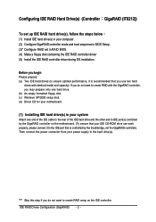
... the IDE cable to the rear of the IDE hard drive and the other end to create RAID array on the motherboard. (To ensure that you begin Please prepare: (a) Two IDE hard drives (to ensure optimal performance, it to the hard drive(s). Then connect the power connector from your computer. (2) Configure GigaRAID controller mode and boot sequence in BIOS Setup. (3)* Configure RAID set up IDE RAID hard drive(s), follow the steps below ¤å (1) Install IDE hard drive(s) in your power supply to the IDE port...
... the IDE cable to the rear of the IDE hard drive and the other end to create RAID array on the motherboard. (To ensure that you begin Please prepare: (a) Two IDE hard drives (to ensure optimal performance, it to the hard drive(s). Then connect the power connector from your computer. (2) Configure GigaRAID controller mode and boot sequence in BIOS Setup. (3)* Configure RAID set up IDE RAID hard drive(s), follow the steps below ¤å (1) Install IDE hard drive(s) in your power supply to the IDE port...
Manual
Page 4
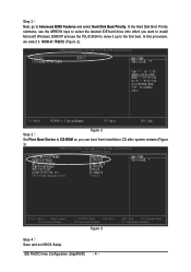
IDE RAID Drives Configuration (GigaRAID) - 4 - In this procedure, we select 1. In the Hard Disk Boot Priority Åé submenu, use the ARROW keys to select the desired IDE hard drive onto which you can boot from Installation CD after system restarts.(Figure 3) CMOS Setup Utility-Copyright (C) 1984-2004 Award Software Advanced BIOS Features : Move Enter: Select F5: Previous Values +/-/PU/PD: Value F10: Save F6: Fail-Safe Defaults Figure 3 ESC: Exit F1: General Help...
IDE RAID Drives Configuration (GigaRAID) - 4 - In this procedure, we select 1. In the Hard Disk Boot Priority Åé submenu, use the ARROW keys to select the desired IDE hard drive onto which you can boot from Installation CD after system restarts.(Figure 3) CMOS Setup Utility-Copyright (C) 1984-2004 Award Software Advanced BIOS Features : Move Enter: Select F5: Previous Values +/-/PU/PD: Value F10: Save F6: Fail-Safe Defaults Figure 3 ESC: Exit F1: General Help...
Manual
Page 14
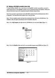
... CD-ROM drive. Figure 17 IDE RAID Drives Configuration (GigaRAID) - 14 - Ác (4) Making a IDE RAID controller driver disk Åé To install Windows 2000/XP onto a hard drive on your motherboard during the Windows setup process. ¤å First of all, you need to copy the driver for an executable program named MENU.exe (Figure 17). The instructions below explain how to the BootDrv folder and look for the IDE RAID controller from the motherboard driver...
... CD-ROM drive. Figure 17 IDE RAID Drives Configuration (GigaRAID) - 14 - Ác (4) Making a IDE RAID controller driver disk Åé To install Windows 2000/XP onto a hard drive on your motherboard during the Windows setup process. ¤å First of all, you need to copy the driver for an executable program named MENU.exe (Figure 17). The instructions below explain how to the BootDrv folder and look for the IDE RAID controller from the motherboard driver...
Manual
Page 6
... low CPU utilization. Once data is entirely different from the lowest speed of PIO mode drive to share CPU's performance. It is damaged, the system will prevent data from Soc concept. When a system is because this system embeds a local CPU to deal with PCI spec. It includes one RAID Chip combining CPU, firmware, advanced PCI controller and IDE controller. This is programmed to the RAID1 mode, two drivers have...
... low CPU utilization. Once data is entirely different from the lowest speed of PIO mode drive to share CPU's performance. It is damaged, the system will prevent data from Soc concept. When a system is because this system embeds a local CPU to deal with PCI spec. It includes one RAID Chip combining CPU, firmware, advanced PCI controller and IDE controller. This is programmed to the RAID1 mode, two drivers have...
Manual
Page 8
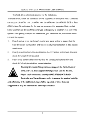
... power cable connector into the connectors on the GigaRAID (IT8212) ATA RAID Controller, can follow the procedures below to buy the cable of the same specification. 8 Warning: Because this system can use the hard drives of the same type and capacity to assure that the hard drives can surely action and unnecessarily incorrect action of data access won't occur. 2. Exactly set up every hard drive's master and slave setting...
... power cable connector into the connectors on the GigaRAID (IT8212) ATA RAID Controller, can follow the procedures below to buy the cable of the same specification. 8 Warning: Because this system can use the hard drives of the same type and capacity to assure that the hard drives can surely action and unnecessarily incorrect action of data access won't occur. 2. Exactly set up every hard drive's master and slave setting...
Manual
Page 38
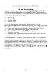
... RAID Controller USER'S MANUAL Driver Installation This section details the procedures to install the GigaRAID (IT8212) ATA RAID Controller driver under Windows once for IDE RAID/SCSI/Serial ATA functioning, the driver must first be installed.) 38 Drive D: 2) Insert a blank formatted floppy disk into the hard disk drive eg. Your system will not have to be listed on -screen instructions to complete installation. (Each time you complete the steps, boot from HDDs in "D:\BootDrv\menu.exe" 4) Information on all chipsets...
... RAID Controller USER'S MANUAL Driver Installation This section details the procedures to install the GigaRAID (IT8212) ATA RAID Controller driver under Windows once for IDE RAID/SCSI/Serial ATA functioning, the driver must first be installed.) 38 Drive D: 2) Insert a blank formatted floppy disk into the hard disk drive eg. Your system will not have to be listed on -screen instructions to complete installation. (Each time you complete the steps, boot from HDDs in "D:\BootDrv\menu.exe" 4) Information on all chipsets...

Manual
Page 39
Boot from floppy with un-installable diskette. The devices that are going to be installed will be different. Press the key to continue the installation of the installation program to insert the GigaRAID (IT8212) ATA RAID Controller Driver diskette into the floppy disk drive then press the key to install, press the key. 4. Boot from floppy with Windows installation diskette. Boot from the device list shown on the list. GigaRAID (IT8212) ATA RAID Controller (Windows 2000/XP) should be...
Boot from floppy with un-installable diskette. The devices that are going to be installed will be different. Press the key to continue the installation of the installation program to insert the GigaRAID (IT8212) ATA RAID Controller Driver diskette into the floppy disk drive then press the key to install, press the key. 4. Boot from floppy with Windows installation diskette. Boot from the device list shown on the list. GigaRAID (IT8212) ATA RAID Controller (Windows 2000/XP) should be...

Manual
Page 45
... RAID Controller Driver diskette into the floppy disk drive then press the key to continue. 5. Boot from CD-ROM with un-installable diskette. Boot from floppy with Windows installation CD. 2. Follow the instruction of Windows 2000. 45 If you need to install third party SCSI or RAID driver" appears on the bottom of the ! Boot from the device list shown on the window then press the key to be listed on the list. The installation will be installed...
... RAID Controller Driver diskette into the floppy disk drive then press the key to continue. 5. Boot from CD-ROM with un-installable diskette. Boot from floppy with Windows installation CD. 2. Follow the instruction of Windows 2000. 45 If you need to install third party SCSI or RAID driver" appears on the bottom of the ! Boot from the device list shown on the window then press the key to be listed on the list. The installation will be installed...
Manual
Page 11
... HDD w Supports IDE bus master operation w Supports ATA133/RAID m ode switch by BIOS w Displays status and error checking m essages during boot-up w Mirroring supports autom atic background rebuilds w Features LBA and Extended Interrupt 13 drive translation in controller onboard BIOS I/O Control w IT8712 Hardware M onitor w CPU / System / Power fan speed detection w CPU temperature detection w System voltage detection w CPU / System / Power fan failure warning w CPU Smart FAN Control BIOS w Use of licensed AWARD BIOS w Supports Dual BIOS /Q-Flash Additional Features w Supports...
... HDD w Supports IDE bus master operation w Supports ATA133/RAID m ode switch by BIOS w Displays status and error checking m essages during boot-up w Mirroring supports autom atic background rebuilds w Features LBA and Extended Interrupt 13 drive translation in controller onboard BIOS I/O Control w IT8712 Hardware M onitor w CPU / System / Power fan speed detection w CPU temperature detection w System voltage detection w CPU / System / Power fan failure warning w CPU Smart FAN Control BIOS w Use of licensed AWARD BIOS w Supports Dual BIOS /Q-Flash Additional Features w Supports...

Manual
Page 22
It will blink when the system enters suspend mode. GA-8I915P Series Motherboard - 22 - Pin No. Definition 7 1 1 GND 2 TXP 3 TXN 4 GND 5 RXN 6 RXP 7 GND 11) PWR_LED PWR_LED is on/off. Pin No. English 10) S_ATA1/S_ATA2/S_ATA3/S_ATA4(SerialATA Connector,Controlled by ICH6) Serial ATA can provide 150M B/s transfer r ate. Definition 1 MPD+ 1 2 MPD- 3 MPD- Please refer to the BIOS setting for the Serial ATA and install the proper driver in order to indicate whether the system is connect with the system power indicator to work properly.
It will blink when the system enters suspend mode. GA-8I915P Series Motherboard - 22 - Pin No. Definition 7 1 1 GND 2 TXP 3 TXN 4 GND 5 RXN 6 RXP 7 GND 11) PWR_LED PWR_LED is on/off. Pin No. English 10) S_ATA1/S_ATA2/S_ATA3/S_ATA4(SerialATA Connector,Controlled by ICH6) Serial ATA can provide 150M B/s transfer r ate. Definition 1 MPD+ 1 2 MPD- 3 MPD- Please refer to the BIOS setting for the Serial ATA and install the proper driver in order to indicate whether the system is connect with the system power indicator to work properly.
Manual
Page 32
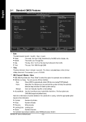
... Mon, Ma y 17 2004 22:3 1:24 Item Help Menu Level} } IDE Channel 0 M aster } IDE Channel 0 Slave [None] [None] Change the day, month, y ear Drive A Driv e B Flopp y 3 Mode Suport Halt On Ba seMe m ory Exte ndedMe m ory Tota l Me m ory [1.44M, 3.5"] [None] [Disabled] [All, But Key b oard] 640K 511M 512M Su n. Enter the appropriate option based on the 24-hour military -time clock. GA-8I915P Series Motherboard - 32 -
... Mon, Ma y 17 2004 22:3 1:24 Item Help Menu Level} } IDE Channel 0 M aster } IDE Channel 0 Slave [None] [None] Change the day, month, y ear Drive A Driv e B Flopp y 3 Mode Suport Halt On Ba seMe m ory Exte ndedMe m ory Tota l Me m ory [1.44M, 3.5"] [None] [Disabled] [All, But Key b oard] 640K 511M 512M Su n. Enter the appropriate option based on the 24-hour military -time clock. GA-8I915P Series Motherboard - 32 -
Manual
Page 53
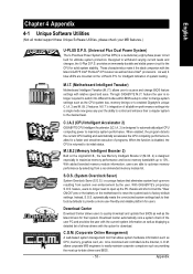
... boot-up -to access and change system settings such as future Intel® processors. M.I.T. (Motherboard Intelligent Tweaker) Motherboard Intelligent Tweaker (M.I .T.'s integration of all platform performance settings into different modes within BIOS setup in order to change BIOS feature settings with the latest LGA775 Intel® Pentium® 4 Processor as well as the CPU system bus, memory timings or to the CPU for download. Download Center automatically runs a system check of the user...
... boot-up -to access and change system settings such as future Intel® processors. M.I.T. (Motherboard Intelligent Tweaker) Motherboard Intelligent Tweaker (M.I .T.'s integration of all platform performance settings into different modes within BIOS setup in order to change BIOS feature settings with the latest LGA775 Intel® Pentium® 4 Processor as well as the CPU system bus, memory timings or to the CPU for download. Download Center automatically runs a system check of the user...
Manual
Page 60
CMOS Setup Utility-Copyright (C) 1984-2004 Award Software } Standard CMOS Features } Advanced BIOS Features } Integrated Peripherals } Power Management Setup } PnP/PCI Configurations } PC Health Status } MB Intelligent Tweaker(M.I.T.) Select Language Load Fail-Safe Defaults Load Optimized Defaults Set Supervisor Password Set User Password Save & Exit Setup Exit Without Saving ESC: Quit F8: Dual BIOS/Q-Flash F3: Change Language F10: Save & Exit Setup Time, Date, Hard Disk Type... Blocking a task and pressing Enter key on your keyboard to enable execution of the task. Blocking ...
CMOS Setup Utility-Copyright (C) 1984-2004 Award Software } Standard CMOS Features } Advanced BIOS Features } Integrated Peripherals } Power Management Setup } PnP/PCI Configurations } PC Health Status } MB Intelligent Tweaker(M.I.T.) Select Language Load Fail-Safe Defaults Load Optimized Defaults Set Supervisor Password Set User Password Save & Exit Setup Exit Without Saving ESC: Quit F8: Dual BIOS/Q-Flash F3: Change Language F10: Save & Exit Setup Time, Date, Hard Disk Type... Blocking a task and pressing Enter key on your keyboard to enable execution of the task. Blocking ...
Manual
Page 61
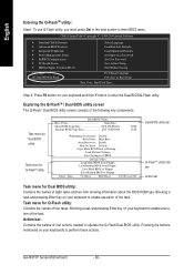
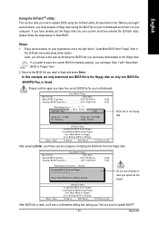
... downloaded to the floppy disk. Dual BIOS Utility Boot From Main Bios Main ROM Type/Size SST 49LF004A Backup ROM Type/Size SST 49LF004A 512K 512K Wide Range Protection Disable 8KNXPU.FAbuatoBRooetcoF1vroefimrlye(s)MEfonauainbnldBe ios 512K Halt On Error Disable Total sizeC:o1p.3y9MMain ROM DataFtroeeBsaiczkeu:p911.50K F5 : Refresh Load Default SDetEtinLg:sDelete Save Settings to CMOS Enter : Run Q-Flash Utility Load Main BIOS from Floppy Load Backup BIOS from Floppy" item in the Q-Flash menu and press Enter button. After pressing Enter, you have entered the Q-Flash utility...
... downloaded to the floppy disk. Dual BIOS Utility Boot From Main Bios Main ROM Type/Size SST 49LF004A Backup ROM Type/Size SST 49LF004A 512K 512K Wide Range Protection Disable 8KNXPU.FAbuatoBRooetcoF1vroefimrlye(s)MEfonauainbnldBe ios 512K Halt On Error Disable Total sizeC:o1p.3y9MMain ROM DataFtroeeBsaiczkeu:p911.50K F5 : Refresh Load Default SDetEtinLg:sDelete Save Settings to CMOS Enter : Run Q-Flash Utility Load Main BIOS from Floppy Load Backup BIOS from Floppy" item in the Q-Flash menu and press Enter button. After pressing Enter, you have entered the Q-Flash utility...

Manual
Page 69
... current audio mode is applied. Line Out STEP 2: After installation of the audio driver, you'll find an icon in "Audio System Status". The function to "Line Out". STEP 3: Click "C-Media 3D Audio Configuration" and then select "Main Setting". Appendix The function to select the function. "Smart Jack" would auto-detect the speaker type you connect and gives you use speakers with amplifier to acquire the best sound...
... current audio mode is applied. Line Out STEP 2: After installation of the audio driver, you'll find an icon in "Audio System Status". The function to "Line Out". STEP 3: Click "C-Media 3D Audio Configuration" and then select "Main Setting". Appendix The function to select the function. "Smart Jack" would auto-detect the speaker type you connect and gives you use speakers with amplifier to acquire the best sound...

Manual
Page 70
... 4 Channel Audio Setup STEP 1 : Connect the front speaker to "Front Speaker Out" and the surround speaker to manually modify speaker setting. The current audio mode is display in the system area. The function to "Surround speaker out". GA-8I915P Series Motherboard - 70 - Double click the icon to adjust speaker volume. The function to select the function. "Smart Jack" would auto-detect the speaker type you connect and gives you 'll find an icon in "Audio...
... 4 Channel Audio Setup STEP 1 : Connect the front speaker to "Front Speaker Out" and the surround speaker to manually modify speaker setting. The current audio mode is display in the system area. The function to "Surround speaker out". GA-8I915P Series Motherboard - 70 - Double click the icon to adjust speaker volume. The function to select the function. "Smart Jack" would auto-detect the speaker type you connect and gives you 'll find an icon in "Audio...

Manual
Page 71
... current audio mode is display in the system area. Front Speaker Out Center/Subwoofer Speaker Out Surround speaker out STEP 3: Click "C-Media 3D Audio Configuration" and then select "Main Setting". The function to manually modify speaker setting. STEP 2: After installation of the audio driver, you the functions to manually modify speaker the settings. Double click the icon to "Center/Subwoofer Speaker Out". Appendix English 5.1 Channel Audio Setup STEP 1 : Connect the front speaker to "Front Speaker Out...
... current audio mode is display in the system area. Front Speaker Out Center/Subwoofer Speaker Out Surround speaker out STEP 3: Click "C-Media 3D Audio Configuration" and then select "Main Setting". The function to manually modify speaker setting. STEP 2: After installation of the audio driver, you the functions to manually modify speaker the settings. Double click the icon to "Center/Subwoofer Speaker Out". Appendix English 5.1 Channel Audio Setup STEP 1 : Connect the front speaker to "Front Speaker Out...

Manual
Page 72
... current audio mode is display in the system area. The function to select the function. GA-8I915P Series Motherboard - 72 - Double click the icon to manually modify speaker setting. "Smart Jack" would auto-detect the speaker type you connect and gives you find an icon in "Audio System Status". The function to "Back surround speaker out". STEP 2: After installation of the audio driver, you the functions to manually modify speaker the settings. Front Speaker...
... current audio mode is display in the system area. The function to select the function. GA-8I915P Series Motherboard - 72 - Double click the icon to manually modify speaker setting. "Smart Jack" would auto-detect the speaker type you connect and gives you find an icon in "Audio System Status". The function to "Back surround speaker out". STEP 2: After installation of the audio driver, you the functions to manually modify speaker the settings. Front Speaker...
Manual
Page 74
... negative pins in EasyTune 4 depends on power. 6. If your board has a Clear CMOS jumper, please refer to enter BIOS and load Fail-Safe Defaults. 7. Re-insert the battery to the steps below: Steps: 1. Disconnect the power cord from MB. 3. Answer: Gigabyte motherboards will not be locked automatically and you can use them. Therefore, we suggest that support RAID function after updating BIOS. If not, please change any setting manually to add an external VGA card...
... negative pins in EasyTune 4 depends on power. 6. If your board has a Clear CMOS jumper, please refer to enter BIOS and load Fail-Safe Defaults. 7. Re-insert the battery to the steps below: Steps: 1. Disconnect the power cord from MB. 3. Answer: Gigabyte motherboards will not be locked automatically and you can use them. Therefore, we suggest that support RAID function after updating BIOS. If not, please change any setting manually to add an external VGA card...

Manual
Page 75
...Cache memory bad AWARD BIOS Beep Codes 1 short: System boots successfully 2 short: CMOS setting error 1 long 1 short: DRAM or M/B error 1 long 2 short: Monitor or display card error 1 long 3 short: Keyboard error 1 long 9 short: BIOS ROM error Continuous long beeps: DRAM error Continuous short beeps: Power error Question 11:For the M/B which have connected any of your own cables to bootup from the IDE/ SCSI/ RAID card ? Question 12:How to set in the BIOS to it depends on the mode(RAID or ATA) that you have RAID function, how to normal ATA mode in the item named RAID controller...
...Cache memory bad AWARD BIOS Beep Codes 1 short: System boots successfully 2 short: CMOS setting error 1 long 1 short: DRAM or M/B error 1 long 2 short: Monitor or display card error 1 long 3 short: Keyboard error 1 long 9 short: BIOS ROM error Continuous long beeps: DRAM error Continuous short beeps: Power error Question 11:For the M/B which have connected any of your own cables to bootup from the IDE/ SCSI/ RAID card ? Question 12:How to set in the BIOS to it depends on the mode(RAID or ATA) that you have RAID function, how to normal ATA mode in the item named RAID controller...


