Manual
Page 1
GA-8I915P Duo (Pro) Intel® Pentium® 4 LGA775 Processor Motherboard User's Manual Rev. 1303 12ME-8I915PUP-1303
GA-8I915P Duo (Pro) Intel® Pentium® 4 LGA775 Processor Motherboard User's Manual Rev. 1303 12ME-8I915PUP-1303
Manual
Page 2
Motherboard GA-8I915P Duo (Pro) Jul. 2, 2004 Motherboard GA-8I915P Duo (Pro) Jul. 2, 2004
Motherboard GA-8I915P Duo (Pro) Jul. 2, 2004 Motherboard GA-8I915P Duo (Pro) Jul. 2, 2004
Manual
Page 4
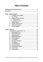
Table of Contents GA-8I915P Duo (Pro) Motherboard Layout 6 Block Diagram ...7 Chapter 1 Hardware Installation 9 1-1 Considerations Prior to Installation 9 1-2 Feature Summary 10 1-3 Installation of the CPU and Heatsink 12 1-3-1 Installation of the CPU 12 1-3-2 ...
Table of Contents GA-8I915P Duo (Pro) Motherboard Layout 6 Block Diagram ...7 Chapter 1 Hardware Installation 9 1-1 Considerations Prior to Installation 9 1-2 Feature Summary 10 1-3 Installation of the CPU and Heatsink 12 1-3-1 Installation of the CPU 12 1-3-2 ...
Manual
Page 6
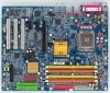
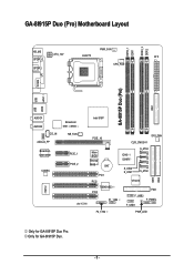
GA-8I915P Duo (Pro) Motherboard Layout DDRII_2 DDRII_1 DDR1 DDR2 PWR_FAN KB_MS ATX_12V LGA775 ATX SPDIF_O SPDIF_I CPU_FAN COMA LPT IDE1 GA-8I915P Duo (Pro) USB USB LAN2 LAN1 AUDIO1 AUDIO2 CD_IN AZALIA_FP Broadcom 5751 /5789 NB_FAN Broadcom 5751/5789 PCIE_1 CODEC PCIE_2 IT8712 IR Intel 915P PCIE_16 CLR_CMOS SYS_FAN Main BIOS Backup BIOS BAT PCI1 PCI2 TSB43AB23 PCI3 F1_1394 ICH6 / ICH6R S_ATA3 S_ATA2 S_ATA1 S_ATA0 VT6410 IDE3 FDD F_USB2 F_PANEL F_USB1 IDE2 F2_1394 PWR_LED Only for GA-8I915P Duo. - 6 - Only for GA-8I915P Duo Pro.
GA-8I915P Duo (Pro) Motherboard Layout DDRII_2 DDRII_1 DDR1 DDR2 PWR_FAN KB_MS ATX_12V LGA775 ATX SPDIF_O SPDIF_I CPU_FAN COMA LPT IDE1 GA-8I915P Duo (Pro) USB USB LAN2 LAN1 AUDIO1 AUDIO2 CD_IN AZALIA_FP Broadcom 5751 /5789 NB_FAN Broadcom 5751/5789 PCIE_1 CODEC PCIE_2 IT8712 IR Intel 915P PCIE_16 CLR_CMOS SYS_FAN Main BIOS Backup BIOS BAT PCI1 PCI2 TSB43AB23 PCI3 F1_1394 ICH6 / ICH6R S_ATA3 S_ATA2 S_ATA1 S_ATA0 VT6410 IDE3 FDD F_USB2 F_PANEL F_USB1 IDE2 F2_1394 PWR_LED Only for GA-8I915P Duo. - 6 - Only for GA-8I915P Duo Pro.
Manual
Page 7
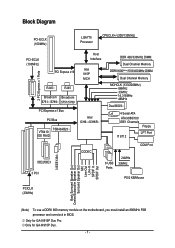
Only for GA-8I915P Duo Pro. Only for GA-8I915P Duo. - 7 - Block Diagram PCI-ECLK (100MHz) LGA775 Processor CPUCLK+/-(200/133MHz) PCI-ECLK (100MHz) PCI Express x16 Host Interface Intel 915P MCH 2 PCI Express x 1 Ports RJ45 ... Center/Subwoofer Speaker Out Surround Speaker Out MIC Line-Out Line-In SPDIF In SPDIF Out (Note) To use a DDRII 600 memory module on the motherboard, you must install an 800MHz FSB processor and overclock in BIOS.
Only for GA-8I915P Duo Pro. Only for GA-8I915P Duo. - 7 - Block Diagram PCI-ECLK (100MHz) LGA775 Processor CPUCLK+/-(200/133MHz) PCI-ECLK (100MHz) PCI Express x16 Host Interface Intel 915P MCH 2 PCI Express x 1 Ports RJ45 ... Center/Subwoofer Speaker Out Surround Speaker Out MIC Line-Out Line-In SPDIF In SPDIF Out (Note) To use a DDRII 600 memory module on the motherboard, you must install an 800MHz FSB processor and overclock in BIOS.
Manual
Page 9
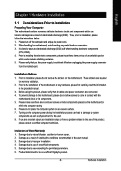
... have these items on the computer power during the installation process can lead to damage to Installation Preparing Your Computer The motherboard contains numerous delicate electronic circuits and components which can become damaged as a result of electrostatic discharge (ESD). These stickers ...are connected. 4. Damage due to be an unofficial Gigabyte product. - 9 - Product determined to use of the product, please consult a certified computer technician. It is switched off the computer ...
... have these items on the computer power during the installation process can lead to damage to Installation Preparing Your Computer The motherboard contains numerous delicate electronic circuits and components which can become damaged as a result of electrostatic discharge (ESD). These stickers ...are connected. 4. Damage due to be an unofficial Gigabyte product. - 9 - Product determined to use of the product, please consult a certified computer technician. It is switched off the computer ...

Manual
Page 10
Only for GA-8I915P Duo Pro. GA-8I915P Duo (Pro) Motherboard - 10 - English 1-2 Feature Summary CPU Chipset Memory Slots IDE Connections FDD Connections Onboard SATA Peripherals Onboard LAN Š Supports the latest Intel® Pentium® 4 ... Š Onboard Broadcom 5751/5789 chip (10/100/1000 Mbit) Š 2 RJ 45 port--LAN1 / LAN2 (Note) To use a DDRII 600 memory module on the motherboard, you must install an 800MHz FSB processor and overclock in BIOS. Only for GA-8I915P Duo.
Only for GA-8I915P Duo Pro. GA-8I915P Duo (Pro) Motherboard - 10 - English 1-2 Feature Summary CPU Chipset Memory Slots IDE Connections FDD Connections Onboard SATA Peripherals Onboard LAN Š Supports the latest Intel® Pentium® 4 ... Š Onboard Broadcom 5751/5789 chip (10/100/1000 Mbit) Š 2 RJ 45 port--LAN1 / LAN2 (Note) To use a DDRII 600 memory module on the motherboard, you must install an 800MHz FSB processor and overclock in BIOS. Only for GA-8I915P Duo.
Manual
Page 12
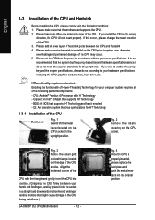
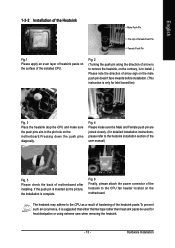
... the wrong direction, the CPU will not insert properly. Fig. 2 Remove the plastic covering on the CPU socket to the CPU during installation.) GA-8I915P Duo (Pro) Motherboard - 12 - Align the indented corner of the CPU with the triangle and gently insert the CPU into position. (Grasping the CPU firmly between... the CPU and heatsink. 4. Fig. 4 Once the CPU is not recommended that the motherboard supports the CPU. 2. Please take note of the one indented corner of the CPU may occur. 5. Please add an even layer of heat ...
... the wrong direction, the CPU will not insert properly. Fig. 2 Remove the plastic covering on the CPU socket to the CPU during installation.) GA-8I915P Duo (Pro) Motherboard - 12 - Align the indented corner of the CPU with the triangle and gently insert the CPU into position. (Grasping the CPU firmly between... the CPU and heatsink. 4. Fig. 4 Once the CPU is not recommended that the motherboard supports the CPU. 2. Please take note of the one indented corner of the CPU may occur. 5. Please add an even layer of heat ...
Manual
Page 13
... heat sink paste be used for detailed installation instructions, please refer to the CPU fan header located on the motherboard. The heatsink may adhere to the pin hole on the motherboard.Pressing down the push pins diagonally. Hardware Installation Fig. 4 Please make sure the push pins aim to the... Male Push Pin The top of Female Push Pin Female Push Pin Fig.1 Please apply an even layer of heatsink paste on the surface of motherboard after installing. Fig. 6 Finally, please attach the power connector of the heatsink to the heatsink installation section of the user manual) Fig. 5...
... heat sink paste be used for detailed installation instructions, please refer to the CPU fan header located on the motherboard. The heatsink may adhere to the pin hole on the motherboard.Pressing down the push pins diagonally. Hardware Installation Fig. 4 Please make sure the push pins aim to the... Male Push Pin The top of Female Push Pin Female Push Pin Fig.1 Please apply an even layer of heatsink paste on the surface of motherboard after installing. Fig. 6 Finally, please attach the power connector of the heatsink to the heatsink installation section of the user manual) Fig. 5...
Manual
Page 14
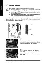
... that the memory used . 2. Insert the DIMM memory module vertically into the DIMM socket. It is recommended that the computer power is supported by the motherboard. GA-8I915P Duo (Pro) Motherboard - 14 - Before installing or removing memory modules, please make sure that they can differ with the following conditions: 1. Memory modules have a foolproof insertion design...
... that the memory used . 2. Insert the DIMM memory module vertically into the DIMM socket. It is recommended that the computer power is supported by the motherboard. GA-8I915P Duo (Pro) Motherboard - 14 - Before installing or removing memory modules, please make sure that they can differ with the following conditions: 1. Memory modules have a foolproof insertion design...
Manual
Page 16
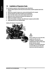
... Installing a PCI Express x 16 expansion card: Please carefully pull out the small whitedrawable bar at the end of expansion card from BIOS. 8. GA-8I915P Duo (Pro) Motherboard - 16 - Remove your expansion card by the small white-drawable bar. Replace your VGA card is locked by following the steps outlined below: ...Replace the screw to the onboard PCI Express x 16 slot and press firmly down on the card are indeed seated in motherboard. 4. English 1-5 Installation of the expansion card. 6. Be sure the metal contacts on the slot .Make sure your computer's chassis cover. 7.
... Installing a PCI Express x 16 expansion card: Please carefully pull out the small whitedrawable bar at the end of expansion card from BIOS. 8. GA-8I915P Duo (Pro) Motherboard - 16 - Remove your expansion card by the small white-drawable bar. Replace your VGA card is locked by following the steps outlined below: ...Replace the screw to the onboard PCI Express x 16 slot and press firmly down on the card are indeed seated in motherboard. 4. English 1-5 Installation of the expansion card. 6. Be sure the metal contacts on the slot .Make sure your computer's chassis cover. 7.
Manual
Page 18
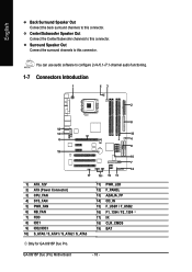
GA-8I915P Duo (Pro) Motherboard - 18 - You can use audio software to this connector. Surround Speaker Out Connect the surround channels to configure 2-/4-/5.1-/7.1-channel audio functioning. 1-7 Connectors Introduction 1 53 2 8 14... S_ATA1 / S_ATA2 / S_ATA3 11) PWR_LED 12) F_PANEL 13) AZALIA_FP 14) CD_IN 15) F_USB1 / F_USB2 16) F1_1394 / F2_1394 17) IR 18) CLR_CMOS 19) BAT Only for GA-8I915P Duo Pro. English Back Surround Speaker Out Connect the back surround channels to this connector. Center/Subwoofer Speaker Out Connect the Center/Subwoofer channels to this connector.
GA-8I915P Duo (Pro) Motherboard - 18 - You can use audio software to this connector. Surround Speaker Out Connect the surround channels to configure 2-/4-/5.1-/7.1-channel audio functioning. 1-7 Connectors Introduction 1 53 2 8 14... S_ATA1 / S_ATA2 / S_ATA3 11) PWR_LED 12) F_PANEL 13) AZALIA_FP 14) CD_IN 15) F_USB1 / F_USB2 16) F1_1394 / F2_1394 17) IR 18) CLR_CMOS 19) BAT Only for GA-8I915P Duo Pro. English Back Surround Speaker Out Connect the back surround channels to this connector. Center/Subwoofer Speaker Out Connect the Center/Subwoofer channels to this connector.
Manual
Page 19
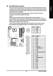
... connector, please make sure that is unable to handle the system voltage requirements. Align the power connector with its proper location on the motherboard before plugging in the power cord ; Pin No. The ATX_12V power connector mainly supplies power to all components and devices are properly installed...12V +12V 13 24 - 19 - Please use a 24-pin ATX power supply, please remove the small cover on the power connector on the motherboard and connect tightly. If the ATX_12V power connector is recommended that a power supply that is able to start . If a power supply is used ...
... connector, please make sure that is unable to handle the system voltage requirements. Align the power connector with its proper location on the motherboard before plugging in the power cord ; Pin No. The ATX_12V power connector mainly supplies power to all components and devices are properly installed...12V +12V 13 24 - 19 - Please use a 24-pin ATX power supply, please remove the small cover on the power connector on the motherboard and connect tightly. If the ATX_12V power connector is recommended that a power supply that is able to start . If a power supply is used ...
Manual
Page 20
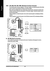
... failure. 1 CPU_FAN 1 PWR_FAN 1 SYS_FAN Pin No. 1 2 3 4 Definition GND +12V Sense Speed Control (Only for CPU_FAN) power connector and possesses a foolproof connection design. Definition 1 1 +12V 2 GND GA-8I915P Duo (Pro) Motherboard - 20 - Caution! Please remember to connect the power to the CPU fan to prevent system overheating and failure. A red power connector wire indicates a positive connection...
... failure. 1 CPU_FAN 1 PWR_FAN 1 SYS_FAN Pin No. 1 2 3 4 Definition GND +12V Sense Speed Control (Only for CPU_FAN) power connector and possesses a foolproof connection design. Definition 1 1 +12V 2 GND GA-8I915P Duo (Pro) Motherboard - 20 - Caution! Please remember to connect the power to the CPU fan to prevent system overheating and failure. A red power connector wire indicates a positive connection...
Manual
Page 22
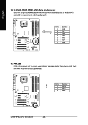
It will blink when the system enters suspend mode. Please refer to the BIOS setting for the Serial ATA and install the proper driver in order to indicate whether the system is on/off. Definition 1 1 MPD+ 2 MPD- 3 MPD- Definition 1 GND 7 1 2 TXP 3 TXN 4 GND 5 RXN 6 RXP 7 GND 11) PWR_LED PWR_LED is connect with the system power indicator to work properly. Pin No. English 10) S_ATA0/S_ATA1/S_ATA2/S_ATA3 (Serial ATA Connector) Serial ATA can provide 150MB/s transfer rate. Pin No. GA-8I915P Duo (Pro) Motherboard - 22 -
It will blink when the system enters suspend mode. Please refer to the BIOS setting for the Serial ATA and install the proper driver in order to indicate whether the system is on/off. Definition 1 1 MPD+ 2 MPD- 3 MPD- Definition 1 GND 7 1 2 TXP 3 TXN 4 GND 5 RXN 6 RXP 7 GND 11) PWR_LED PWR_LED is connect with the system power indicator to work properly. Pin No. English 10) S_ATA0/S_ATA1/S_ATA2/S_ATA3 (Serial ATA Connector) Serial ATA can provide 150MB/s transfer rate. Pin No. GA-8I915P Duo (Pro) Motherboard - 22 -
Manual
Page 24
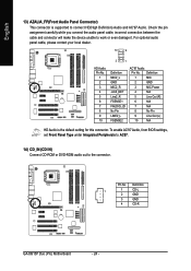
Definition 1 1 CD-L 2 GND 3 GND 4 CD-R GA-8I915P Duo (Pro) Motherboard - 24 - Definition 1 MIC 2 GND 3 MIC Power 4 N/A 5 Line Out (R) 6 N/A 7 N/A 8 No Pin 9 Line Out (L) 10 N/A HD Audio is supported to work or even damage it. English 13) ...
Definition 1 1 CD-L 2 GND 3 GND 4 CD-R GA-8I915P Duo (Pro) Motherboard - 24 - Definition 1 MIC 2 GND 3 MIC Power 4 N/A 5 Line Out (R) 6 N/A 7 N/A 8 No Pin 9 Line Out (L) 10 N/A HD Audio is supported to work or even damage it. English 13) ...
Manual
Page 26
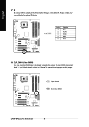
Definition 1 VCC 2 No Pin 1 3 IR RX 4 GND 5 IR TX 18) CLR_CMOS (Clear CMOS) You may clear the CMOS data to prevent from improper use this jumper. To clear CMOS, temporarily short 1-2 pin. Please contact your nearest dealer for optional IR device. Default doesn't include the "Shunter" to its default values by this jumper. 1 Open: Normal 1 Short: Clear CMOS GA-8I915P Duo (Pro) Motherboard - 26 - English 17) IR Be careful with the polarity of the IR connector while you connect the IR. Pin No.
Definition 1 VCC 2 No Pin 1 3 IR RX 4 GND 5 IR TX 18) CLR_CMOS (Clear CMOS) You may clear the CMOS data to prevent from improper use this jumper. To clear CMOS, temporarily short 1-2 pin. Please contact your nearest dealer for optional IR device. Default doesn't include the "Shunter" to its default values by this jumper. 1 Open: Normal 1 Short: Clear CMOS GA-8I915P Duo (Pro) Motherboard - 26 - English 17) IR Be careful with the polarity of the IR connector while you connect the IR. Pin No.
Manual
Page 28
English GA-8I915P Duo (Pro) Motherboard - 28 -
English GA-8I915P Duo (Pro) Motherboard - 28 -
Manual
Page 29
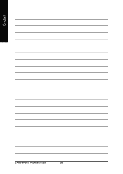
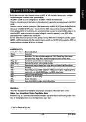
... settings. Only for Main Menu Main Menu The on-line description of the highlighted setup function is turned on the motherboard supplies the necessary power to a new BIOS, either Gigabyte's Q-Flash or @BIOS utility can enter the BIOS setup screen by pressing "Ctrl + F1". If you wish ...and update BIOS from BIOS default table Load the Optimized Defaults Dual BIOS /Q-Flash utility System Information Save all the CMOS changes, only for GA-8I915P Duo Pro. - 29 - Exit current page and return to Main Menu Increase the numeric value or make changes Decrease the numeric value or make ...
... settings. Only for Main Menu Main Menu The on-line description of the highlighted setup function is turned on the motherboard supplies the necessary power to a new BIOS, either Gigabyte's Q-Flash or @BIOS utility can enter the BIOS setup screen by pressing "Ctrl + F1". If you wish ...and update BIOS from BIOS default table Load the Optimized Defaults Dual BIOS /Q-Flash utility System Information Save all the CMOS changes, only for GA-8I915P Duo Pro. - 29 - Exit current page and return to Main Menu Increase the numeric value or make changes Decrease the numeric value or make ...
Manual
Page 30
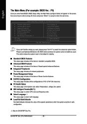
... Exit Without Saving F3: Change Language 1 F10: Save & Exit Setup Time, Date, Hard Disk Type... This action makes the system reset to the default for GA-8I915P Duo Pro. GA-8I915P Duo (Pro) Motherboard - 30 - If you can't find the setting you enter Award BIOS CMOS Setup Utility, the Main Menu (as usual. Please Load Optimized Defaults in safe...
... Exit Without Saving F3: Change Language 1 F10: Save & Exit Setup Time, Date, Hard Disk Type... This action makes the system reset to the default for GA-8I915P Duo Pro. GA-8I915P Duo (Pro) Motherboard - 30 - If you can't find the setting you enter Award BIOS CMOS Setup Utility, the Main Menu (as usual. Please Load Optimized Defaults in safe...


