
Manual
Page 4
Table of Content GA-8I915ME Series Motherboard Layout 6 Block Diagram ...7 Chapter 1 Hardware Installation 9 1-1 Considerations Prior to Installation 9 1-2 Feature Summary 10 1-3 Installation of the CPU and Heatsink 12 1-3-1 Installation of the CPU 12 1-3-2 Installation of the Heatsink 13 1-4 Installation of Memory 14 1-5 Installation of Expansion Cards 16 1-5-1 What is G.E.A.R 17 1-5-2 Graphics Card Support List 17 1-6 I/O Back...
Table of Content GA-8I915ME Series Motherboard Layout 6 Block Diagram ...7 Chapter 1 Hardware Installation 9 1-1 Considerations Prior to Installation 9 1-2 Feature Summary 10 1-3 Installation of the CPU and Heatsink 12 1-3-1 Installation of the CPU 12 1-3-2 Installation of the Heatsink 13 1-4 Installation of Memory 14 1-5 Installation of Expansion Cards 16 1-5-1 What is G.E.A.R 17 1-5-2 Graphics Card Support List 17 1-6 I/O Back...
Manual
Page 9
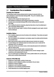
... components as well as physical harm to the user. 8. Damage due to wear an electrostatic discharge (ESD) cuff when handling electronic components (CPU, RAM). 4. Before using the product, please verify that the power supply is best to use of violating the conditions recommended in the user... manual. 3. Damage due to be an unofficial Gigabyte product. - 9 - Please verify that all cables and power connectors are no leftover screws or metal components placed on the motherboard. These...
... components as well as physical harm to the user. 8. Damage due to wear an electrostatic discharge (ESD) cuff when handling electronic components (CPU, RAM). 4. Before using the product, please verify that the power supply is best to use of violating the conditions recommended in the user... manual. 3. Damage due to be an unofficial Gigabyte product. - 9 - Please verify that all cables and power connectors are no leftover screws or metal components placed on the motherboard. These...
Manual
Page 10
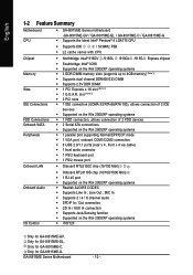
Only for GA-8I915ME-C. Only for GA-8I915ME-G. Only for GA-8I915ME-GL. English 1-2 Feature Summary Motherboard CPU Š GA-8I915ME Series motherboard -GA-8I915ME-GV / GA-8I915ME-GL / GA-8I915ME-C / GA-8I915ME-G Š Supports the latest Intel® Pentium® 4 LGA775 CPU Š Supports 800 / 533MHz FSB Š L2 cache varies with CPU Chipset Memory Slots IDE Connections FDD Connections Onboard SATA Peripherals Onboard LAN Š Northbridge: Intel®...
Only for GA-8I915ME-C. Only for GA-8I915ME-G. Only for GA-8I915ME-GL. English 1-2 Feature Summary Motherboard CPU Š GA-8I915ME Series motherboard -GA-8I915ME-GV / GA-8I915ME-GL / GA-8I915ME-C / GA-8I915ME-G Š Supports the latest Intel® Pentium® 4 LGA775 CPU Š Supports 800 / 533MHz FSB Š L2 cache varies with CPU Chipset Memory Slots IDE Connections FDD Connections Onboard SATA Peripherals Onboard LAN Š Northbridge: Intel®...
Manual
Page 11
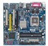
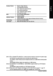
... with AGP 8X slot. - 11 - GA-8I915ME-C(910GL chipset) only supports up to 2GB memory. (Note 2) GA-8I915ME-GV / GA-8I915ME-GL / GA-8I915ME-C supports transfer up to PCI Express x4 mode. Hardware Installation English Hardware Monitor Š System voltage detection Š CPU temperature detection Š CPU / System fan speed detection Š CPU warning temperature Š CPU / System fan failure warning Š...
... with AGP 8X slot. - 11 - GA-8I915ME-C(910GL chipset) only supports up to 2GB memory. (Note 2) GA-8I915ME-GV / GA-8I915ME-GL / GA-8I915ME-C supports transfer up to PCI Express x4 mode. Hardware Installation English Hardware Monitor Š System voltage detection Š CPU temperature detection Š CPU / System fan speed detection Š CPU warning temperature Š CPU / System fan failure warning Š...
Manual
Page 12
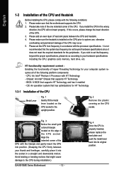
..., etc. If this occurs, please change the insert direction of the CPU. Fig. 2 Remove the plastic covering on the CPU prior to the upright position. Please set beyond the proper specifications, please do so according to the CPU during installation.) GA-8I915ME Series Motherboard - 12 - CPU: An Intel® Pentium 4 Processor with HT Technology - Avoid twisting...
..., etc. If this occurs, please change the insert direction of the CPU. Fig. 2 Remove the plastic covering on the CPU prior to the upright position. Please set beyond the proper specifications, please do so according to the CPU during installation.) GA-8I915ME Series Motherboard - 12 - CPU: An Intel® Pentium 4 Processor with HT Technology - Avoid twisting...
Manual
Page 13
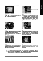
...on the motherboard. Fig. 2 (Turning the push pin along the direction of arrow is to remove the heatsink, on the contrary, is to the CPU as the picture, the installation is suggested that either thermal tape rather than heat sink paste be used for Intel boxed fan) Fig. 3 Place ...the heatsink atop the CPU and make sure the Male and Female push pin are joined closely. (for detailed installation instructions, please refer to the heatsink installation section of the...
...on the motherboard. Fig. 2 (Turning the push pin along the direction of arrow is to remove the heatsink, on the contrary, is to the CPU as the picture, the installation is suggested that either thermal tape rather than heat sink paste be used for Intel boxed fan) Fig. 3 Place ...the heatsink atop the CPU and make sure the Male and Female push pin are joined closely. (for detailed installation instructions, please refer to the heatsink installation section of the...
Manual
Page 22
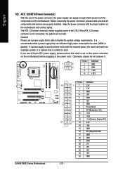
...power supply that can supply enough stable power to all components and devices are properly installed. Pin No. Definition 3 4 1 GND 1 2 2 GND 3 +12V 4 +12V GA-8I915ME Series Motherboard 13 24 - 22 - Caution! If a power supply is used (300W or greater). Otherwise, please do not remove it. It is unable to start... -12V GND PS_ON(soft On/Off) GND GND GND -5V +5V +5V +5V GND If the ATX_12V power connector is able to the CPU. Please use a 24-pin ATX power supply, please remove the small cover on the power connector on the motherboard and connect tightly. Align the...
...power supply that can supply enough stable power to all components and devices are properly installed. Pin No. Definition 3 4 1 GND 1 2 2 GND 3 +12V 4 +12V GA-8I915ME Series Motherboard 13 24 - 22 - Caution! If a power supply is used (300W or greater). Otherwise, please do not remove it. It is unable to start... -12V GND PS_ON(soft On/Off) GND GND GND -5V +5V +5V +5V GND If the ATX_12V power connector is able to the CPU. Please use a 24-pin ATX power supply, please remove the small cover on the power connector on the motherboard and connect tightly. Align the...
Manual
Page 23
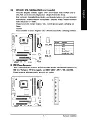
.... 34 33 2 1 - 23 - Please connect the red power connector wire to prevent system overheating and failure. Please remember to connect the power to the CPU fan to prevent CPU overheating and failure. 1 CPU_FAN 1 SYS_FAN Pin No. 1 2 3 4 Definition GND +12V Sense Speed Control (Only for CPU_FAN) power connector and possesses a foolproof connection design...
.... 34 33 2 1 - 23 - Please connect the red power connector wire to prevent system overheating and failure. Please remember to connect the power to the CPU fan to prevent CPU overheating and failure. 1 CPU_FAN 1 SYS_FAN Pin No. 1 2 3 4 Definition GND +12V Sense Speed Control (Only for CPU_FAN) power connector and possesses a foolproof connection design...
Manual
Page 34
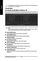
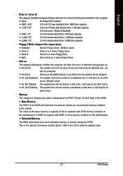
... / Voltage Control This setup page is control CPU clock and frequency ratio. „ Load Fail-Safe Defaults Fail-Safe Defaults indicates the value of the system parameters which the system would be in safe configuration. The Main Menu (For example: GA-8I915ME-GV / BIOS Ver.: F2) Once you ...want, please press "Ctrl+F1" to search the advanced option hidden. GA-8I915ME Series Motherboard - 34 - English The BIOS Setup menus described in the BIOS when...
... / Voltage Control This setup page is control CPU clock and frequency ratio. „ Load Fail-Safe Defaults Fail-Safe Defaults indicates the value of the system parameters which the system would be in safe configuration. The Main Menu (For example: GA-8I915ME-GV / BIOS Ver.: F2) Once you ...want, please press "Ctrl+F1" to search the advanced option hidden. GA-8I915ME Series Motherboard - 34 - English The BIOS Setup menus described in the BIOS when...
Manual
Page 37
.... 1.2M, 5.25" 5.25 inch AT-type high-density drive; 1.2M byte capacity (3.5 inch when 3 Mode is the amount of memory located above 1 MB in the CPU's memory address map. - 37 - Floppy 3 Mode Support (for all other errors. it will not stop for all other errors. English Drive A / Drive B The category identifies...
.... 1.2M, 5.25" 5.25 inch AT-type high-density drive; 1.2M byte capacity (3.5 inch when 3 Mode is the amount of memory located above 1 MB in the CPU's memory address map. - 37 - Floppy 3 Mode Support (for all other errors. it will not stop for all other errors. English Drive A / Drive B The category identifies...
Manual
Page 38
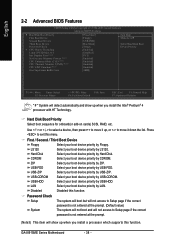
...RAID, etc. Hard Disk Select your boot device priority by Hard Disk. USB-ZIP Select your boot device priority by USB-ZIP. GA-8I915ME Series Motherboard - 38 - LAN Select your boot device priority by LAN. English 2-2 Advanced BIOS Features CMOS Setup Utility-Copyright (C)...-Threading Limit CPUID Max. to move it up, or to 3 Init Display First (Note1) No-Execute Memory Protect (Note3) CPU Enhanced Halt (C1E) (Note3) CPU Thermal Monitor 2(TM2) (Note3) CPU EIST Function (Note3) On-Chip Frame Buffer Size [Press Enter] [Floppy] [USB-FDD] [Hard Disk] [Setup] [Enabled] [...
...RAID, etc. Hard Disk Select your boot device priority by Hard Disk. USB-ZIP Select your boot device priority by USB-ZIP. GA-8I915ME Series Motherboard - 38 - LAN Select your boot device priority by LAN. English 2-2 Advanced BIOS Features CMOS Setup Utility-Copyright (C)...-Threading Limit CPUID Max. to move it up, or to 3 Init Display First (Note1) No-Execute Memory Protect (Note3) CPU Enhanced Halt (C1E) (Note3) CPU Thermal Monitor 2(TM2) (Note3) CPU EIST Function (Note3) On-Chip Frame Buffer Size [Press Enter] [Floppy] [USB-FDD] [Hard Disk] [Setup] [Enabled] [...
Manual
Page 39
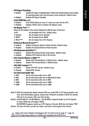
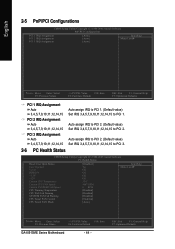
... first to PCI Express x16 mode; BIOS item will show up to 33MHz and compatible with multi processors mode supported. (Default value) Disabled Disables CPU Hyper Threading. GA-8I915ME-G supports transfer up to PCI Express x4 mode; G.E.A.R supporting transfer up to PCI Express. BIOS item will display "PEG". (Note3) This item will display...
... first to PCI Express x16 mode; BIOS item will show up to 33MHz and compatible with multi processors mode supported. (Default value) Disabled Disables CPU Hyper Threading. GA-8I915ME-G supports transfer up to PCI Express x4 mode; G.E.A.R supporting transfer up to PCI Express. BIOS item will display "PEG". (Note3) This item will display...
Manual
Page 44
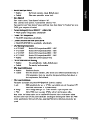
... Open Status Case Opened Vcore DDR25V +3.3V +12V Current CPU Temperature Current CPU FAN Speed Current SYSTEM FAN Speed CPU Warning Temperature CPU FAN Fail Warning SYSTEM FAN Fail Warning CPU Smart FAN Control CPU Smart FAN Mode [Disabled] Yes OK OK OK OK ...33oC 4687 RPM 0 RPM [Disabled] [Disabled] [Disabled] [Enabled] [Auto] Item Help Menu Level` KLJI: Move Enter: Select F5: Previous Values +/-/PU/PD: Value F10: Save F6: Fail-Save Default GA-8I915ME...
... Open Status Case Opened Vcore DDR25V +3.3V +12V Current CPU Temperature Current CPU FAN Speed Current SYSTEM FAN Speed CPU Warning Temperature CPU FAN Fail Warning SYSTEM FAN Fail Warning CPU Smart FAN Control CPU Smart FAN Mode [Disabled] Yes OK OK OK OK ...33oC 4687 RPM 0 RPM [Disabled] [Disabled] [Disabled] [Enabled] [Auto] Item Help Menu Level` KLJI: Move Enter: Select F5: Previous Values +/-/PU/PD: Value F10: Save F6: Fail-Save Default GA-8I915ME...
Manual
Page 45
... "Enabled" and save CMOS, your computer will restart. PWM Set to PWM when you installed and sets the optimal CPU Smart FAN control mode for CPU fans with a 3-pin fan power cable. Note: In fact, the Voltage option can adjust the fan speed with... a 4-pin fan power cable. Current CPU Temperature Detect CPU temperature automatically. Monitor CPU temperature at 60oC / 140oF. CPU Warning Temperature 60oC / 140oF 70oC / 158oF 80oC / 176oF 90oC / 194oF Disabled Monitor CPU temperature at 80oC / 176oF. Monitor CPU temperature at 90oC / 194oF. When this function is...
... "Enabled" and save CMOS, your computer will restart. PWM Set to PWM when you installed and sets the optimal CPU Smart FAN control mode for CPU fans with a 3-pin fan power cable. Note: In fact, the Voltage option can adjust the fan speed with... a 4-pin fan power cable. Current CPU Temperature Detect CPU temperature automatically. Monitor CPU temperature at 60oC / 140oF. CPU Warning Temperature 60oC / 140oF 70oC / 158oF 80oC / 176oF 90oC / 194oF Disabled Monitor CPU temperature at 80oC / 176oF. Monitor CPU temperature at 90oC / 194oF. When this function is...
Manual
Page 46
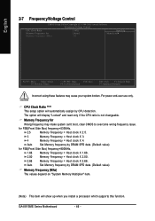
...66. 2.00 Memory Frequency = Host clock X 2.00. 2.66 Memory Frequency = Host clock X 2.66. Auto Set Memory frequency by CPU detection. The option will show up when you install a processor which supports this function. Auto Set Memory frequency by DRAM SPD data. (...system broken. CPU Clock Ratio (Note) This setup option will automatically assign by DRAM SPD data. (Default value) for FSB(Front Side Bus) frequency=533MHz, 2.5 Memory Frequency = Host clock X 2.5. 3 Memory Frequency = Host clock X 3. 4 Memory Frequency = Host clock X 4. GA-8I915ME Series Motherboard ...
...66. 2.00 Memory Frequency = Host clock X 2.00. 2.66 Memory Frequency = Host clock X 2.66. Auto Set Memory frequency by CPU detection. The option will show up when you install a processor which supports this function. Auto Set Memory frequency by DRAM SPD data. (...system broken. CPU Clock Ratio (Note) This setup option will automatically assign by DRAM SPD data. (Default value) for FSB(Front Side Bus) frequency=533MHz, 2.5 Memory Frequency = Host clock X 2.5. 3 Memory Frequency = Host clock X 3. 4 Memory Frequency = Host clock X 4. GA-8I915ME Series Motherboard ...
Manual
Page 55
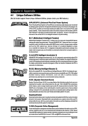
... and boost memory bandwidth up errors resulting from system over-enhancement by selecting from a recommended memory module list. C.I.A.2 (CPU Intelligent Accelerator 2) GIGABYTE CPU Intelligent Accelerator 2(C.I .T. M.I .T.'s integration of the user PC and provides the user with the current system information as ... (System Overclock Saver) System Overclock Saver (S.O.S.) is a unique feature that allows system hardware information such as the CPU system bus, memory timings or to enabled Gigabyte's unique C.I.A. 2 and M.I .B. 2) is no longer need to open up -to the desired level. Download...
... and boost memory bandwidth up errors resulting from system over-enhancement by selecting from a recommended memory module list. C.I.A.2 (CPU Intelligent Accelerator 2) GIGABYTE CPU Intelligent Accelerator 2(C.I .T. M.I .T.'s integration of the user PC and provides the user with the current system information as ... (System Overclock Saver) System Overclock Saver (S.O.S.) is a unique feature that allows system hardware information such as the CPU system bus, memory timings or to enabled Gigabyte's unique C.I.A. 2 and M.I .B. 2) is no longer need to open up -to the desired level. Download...
Manual
Page 56
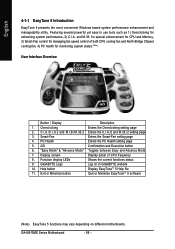
... 6. Display screen Display panel of both CPU cooling fan and North-Bridge Chipset cooling fan, 4) PC health for enhancing system performance, 2) C.I.A. Help button Display EasyTuneTM 5 Help file 11. GA-8I915ME Series Motherboard - 56 - Smart-Fan ...control of CPU frequency 8. Overclocking Enters the Overclocking setting page 2. "Easy Mode" & "Advance Mode" Toggles between Easy and Advance Mode 7. C.I.A./C.I.A.2 and M.I.B./M.I.B.2 Enters the C.I.A./2 and M.I .B. GIGABYTE Logo Log on different motherboards. Featuring several powerful yet easy to GIGABYTE website 10...
... 6. Display screen Display panel of both CPU cooling fan and North-Bridge Chipset cooling fan, 4) PC health for enhancing system performance, 2) C.I.A. Help button Display EasyTuneTM 5 Help file 11. GA-8I915ME Series Motherboard - 56 - Smart-Fan ...control of CPU frequency 8. Overclocking Enters the Overclocking setting page 2. "Easy Mode" & "Advance Mode" Toggles between Easy and Advance Mode 7. C.I.A./C.I.A.2 and M.I.B./M.I.B.2 Enters the C.I.A./2 and M.I .B. GIGABYTE Logo Log on different motherboards. Featuring several powerful yet easy to GIGABYTE website 10...


