Manual
Page 1
GA-8I915GL-MF Intel® Pentium® 4 LGA775 Processor Motherboard User's Manual Rev. 1001 12ME-I915GLMF-1001
GA-8I915GL-MF Intel® Pentium® 4 LGA775 Processor Motherboard User's Manual Rev. 1001 12ME-I915GLMF-1001
Manual
Page 2
Motherboard GA-8I915GL-MF Feb. 22, 2005 Motherboard GA-8I915GL-MF Feb. 22, 2005
Motherboard GA-8I915GL-MF Feb. 22, 2005 Motherboard GA-8I915GL-MF Feb. 22, 2005
Manual
Page 4
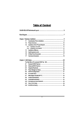
Table of Content GA-8I915GL-MF Motherboard Layout 6 Block Diagram ...7 Chapter 1 Hardware Installation 9 1-1 Considerations Prior to Installation 9 1-2 Feature Summary 10 1-3 Installation of the CPU and Heatsink 12 1-3-1 Installation of the CPU ...
Table of Content GA-8I915GL-MF Motherboard Layout 6 Block Diagram ...7 Chapter 1 Hardware Installation 9 1-1 Considerations Prior to Installation 9 1-2 Feature Summary 10 1-3 Installation of the CPU and Heatsink 12 1-3-1 Installation of the CPU ...
Manual
Page 6
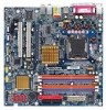
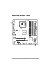
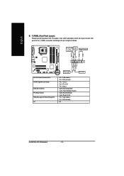
SYS_FAN CI IR GA-8I915GL-MF Motherboard Layout IT8712 KB_MS SPDIF_O SPDIF_I CPU_FAN ATX VGA LPT R_USB ATX_12V LGA775 GA-8I915GL-MF DDR1 DDR2 USB LAN AZALIA_FP AUDIO1 AUDIO2 RTL8110S CD_IN CODEC PCIE_1 COMA COMB Intel 915GL IDE FDD DDR3 DDR4 PCI1 BAT PCI2 TSB43AB23 ICH6 SATA3 SATA2 SATA1 SATA0 F2_1394 F1_1394 F_USB1 F_USB2 BIOS F_PANEL CLR_CMOS - 6 -
SYS_FAN CI IR GA-8I915GL-MF Motherboard Layout IT8712 KB_MS SPDIF_O SPDIF_I CPU_FAN ATX VGA LPT R_USB ATX_12V LGA775 GA-8I915GL-MF DDR1 DDR2 USB LAN AZALIA_FP AUDIO1 AUDIO2 RTL8110S CD_IN CODEC PCIE_1 COMA COMB Intel 915GL IDE FDD DDR3 DDR4 PCI1 BAT PCI2 TSB43AB23 ICH6 SATA3 SATA2 SATA1 SATA0 F2_1394 F1_1394 F_USB1 F_USB2 BIOS F_PANEL CLR_CMOS - 6 -
Manual
Page 10
...; 1 RJ 45 port Š ALC880 CODEC Š Supports Jack Sensing function Š Supports 2 / 4 / 6 / 8 channel audio Š Supports Line In ; Surround Speaker Out (Rear Speaker Out) ; GA-8I915GL-MF Motherboard - 10 - For example, 4 GB of memory size will instead be shown as 3.xxGB memory during system startup. MIC ; Line Out (Front Speaker Out) ; English...
...; 1 RJ 45 port Š ALC880 CODEC Š Supports Jack Sensing function Š Supports 2 / 4 / 6 / 8 channel audio Š Supports Line In ; Surround Speaker Out (Rear Speaker Out) ; GA-8I915GL-MF Motherboard - 10 - For example, 4 GB of memory size will instead be shown as 3.xxGB memory during system startup. MIC ; Line Out (Front Speaker Out) ; English...
Manual
Page 12
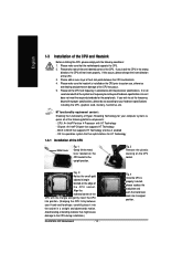
...-Threading Technology for the peripherals. BIOS: A BIOS that supports HT Technology - Fig. 2 Remove the plastic covering on the CPU prior to the CPU during installation.) GA-8I915GL-MF Motherboard - 12 - English 1-3 Installation of the CPU and Heatsink Before installing the CPU, please comply with the following platform components: - Please make sure the heatsink...
...-Threading Technology for the peripherals. BIOS: A BIOS that supports HT Technology - Fig. 2 Remove the plastic covering on the CPU prior to the CPU during installation.) GA-8I915GL-MF Motherboard - 12 - English 1-3 Installation of the CPU and Heatsink Before installing the CPU, please comply with the following platform components: - Please make sure the heatsink...
Manual
Page 14
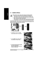
The memory capacity used can be inserted only in one direction. GA-8I915GL-MF Motherboard - 14 - Memory modules have a foolproof insertion design. Close the plastic clip at both edges of the DIMM slots to prevent hardware damage. 3. If you ...
The memory capacity used can be inserted only in one direction. GA-8I915GL-MF Motherboard - 14 - Memory modules have a foolproof insertion design. Close the plastic clip at both edges of the DIMM slots to prevent hardware damage. 3. If you ...
Manual
Page 15
We'll strongly recommend our user to work. Hardware Installation English GA-8I915GL-MF supports the Dual Channel Technology. GA-8I915GL-MF includes 4 DIMM sockets, and each Channel has two DIMM sockets as following: Channel A : DDR 1, DDR 2 Channel B : DDR 3, DDR 4 If you install two memory modules in ...
We'll strongly recommend our user to work. Hardware Installation English GA-8I915GL-MF supports the Dual Channel Technology. GA-8I915GL-MF includes 4 DIMM sockets, and each Channel has two DIMM sockets as following: Channel A : DDR 1, DDR 2 Channel B : DDR 3, DDR 4 If you install two memory modules in ...
Manual
Page 16
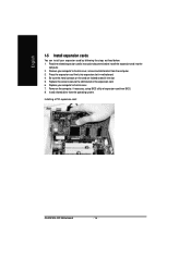
... the computer. 2. Replace the screw to secure the slot bracket of expansion card from BIOS. 8. Install related driver from the computer. 3. Installing a PCI expansion card: GA-8I915GL-MF Motherboard - 16 - Be sure the metal contacts on the computer, if necessary, setup BIOS utility of the expansion card. 6. Remove your computer's chassis cover, screws...
... the computer. 2. Replace the screw to secure the slot bracket of expansion card from BIOS. 8. Install related driver from the computer. 3. Installing a PCI expansion card: GA-8I915GL-MF Motherboard - 16 - Be sure the metal contacts on the computer, if necessary, setup BIOS utility of the expansion card. 6. Remove your computer's chassis cover, screws...
Manual
Page 18
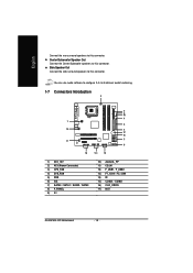
... 7) SATA0 / SATA1 / SATA2 / SATA3 8) F_PANEL 9) CI 10) AZALIA_FP 11) CD_IN 12) F_USB1 / F_USB2 13) F1_1394 / F2_1394 14) IR 15) COMA / COMB 16) CLR_CMOS 17) BAT GA-8I915GL-MF Motherboard - 18 - You can use audio software to this connector.
... 7) SATA0 / SATA1 / SATA2 / SATA3 8) F_PANEL 9) CI 10) AZALIA_FP 11) CD_IN 12) F_USB1 / F_USB2 13) F1_1394 / F2_1394 14) IR 15) COMA / COMB 16) CLR_CMOS 17) BAT GA-8I915GL-MF Motherboard - 18 - You can use audio software to this connector.
Manual
Page 20
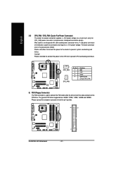
... (Only for CPU_FAN) power connector and possesses a foolproof connection design. Please remember to connect the power to the cooler to the pin1 position. 34 33 GA-8I915GL-MF Motherboard 2 1 - 20 - English 3/4) CPU_FAN / SYS_FAN (Cooler Fan Power Connector) The cooler fan power connector supplies a +12V power voltage via a 3-pin/4-pin (only for CPU_FAN) 5) FDD...
... (Only for CPU_FAN) power connector and possesses a foolproof connection design. Please remember to connect the power to the cooler to the pin1 position. 34 33 GA-8I915GL-MF Motherboard 2 1 - 20 - English 3/4) CPU_FAN / SYS_FAN (Cooler Fan Power Connector) The cooler fan power connector supplies a +12V power voltage via a 3-pin/4-pin (only for CPU_FAN) 5) FDD...
Manual
Page 22
...- Pin 3: NC Pin 4: Data(-) Open: Normal Operation Close: Reset Hardware System Open: Normal Operation Close: Power On/Off Pin 1: LED anode(+) Pin 2: LED cathode(-) NC GA-8I915GL-MF Motherboard - 22 - SPEAK+ PWPW+ MSGMSG+ 2 20 1 19 NC RES+ RESHD- HD+ HD (IDE Hard Disk Active LED) SPEAK (Speaker Connector) RES (Reset Switch) PW (Power...
...- Pin 3: NC Pin 4: Data(-) Open: Normal Operation Close: Reset Hardware System Open: Normal Operation Close: Power On/Off Pin 1: LED anode(+) Pin 2: LED cathode(-) NC GA-8I915GL-MF Motherboard - 22 - SPEAK+ PWPW+ MSGMSG+ 2 20 1 19 NC RES+ RESHD- HD+ HD (IDE Hard Disk Active LED) SPEAK (Speaker Connector) RES (Reset Switch) PW (Power...
Manual
Page 24
... out to work or even damage it. Definition 1 Power 2 Power 9 1 3 USB DX- 4 USB Dy- 10 2 5 USB DX+ 6 USB Dy+ 7 GND 8 GND 9 No Pin 10 NC GA-8I915GL-MF Motherboard - 24 -
... out to work or even damage it. Definition 1 Power 2 Power 9 1 3 USB DX- 4 USB Dy- 10 2 5 USB DX+ 6 USB Dy+ 7 GND 8 GND 9 No Pin 10 NC GA-8I915GL-MF Motherboard - 24 -
Manual
Page 26
... data to prevent from improper use this jumper. Default doesn't include the "Shunter" to its default values by this jumper. 1 Open: Normal 1 Short :Clear CMOS GA-8I915GL-MF Motherboard - 26 - Check the pin assignment carefully while you connect the COM cable, incorrect connection between the cable and connector will make the device unable...
... data to prevent from improper use this jumper. Default doesn't include the "Shunter" to its default values by this jumper. 1 Open: Normal 1 Short :Clear CMOS GA-8I915GL-MF Motherboard - 26 - Check the pin assignment carefully while you connect the COM cable, incorrect connection between the cable and connector will make the device unable...
Manual
Page 30
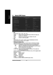
... the system and Setup, or just to search the advanced option hidden. This action makes the system reset to accept or enter the sub-menu. GA-8I915GL-MF Motherboard - 30 - Use arrow keys to select among the items and press to the default for stability. „ Standard CMOS Features This setup page includes...
... the system and Setup, or just to search the advanced option hidden. This action makes the system reset to accept or enter the sub-menu. GA-8I915GL-MF Motherboard - 30 - Use arrow keys to select among the items and press to the default for stability. „ Standard CMOS Features This setup page includes...
Manual
Page 32
... for automatic device detection. The four options are used and the system will skip the automatic detection step and allow for faster system start up. GA-8I915GL-MF Motherboard - 32 - Jan. IDE Channel 0/2/3 Master, Slave IDE HDD Auto-Detection Press "Enter" to select this to Sat, determined by the BIOS and is 13...
... for automatic device detection. The four options are used and the system will skip the automatic detection step and allow for faster system start up. GA-8I915GL-MF Motherboard - 32 - Jan. IDE Channel 0/2/3 Master, Slave IDE HDD Auto-Detection Press "Enter" to select this to Sat, determined by the BIOS and is 13...
Manual
Page 34
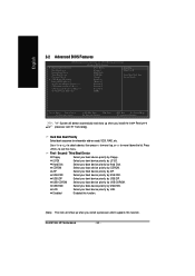
... Software Advanced BIOS Features ` Hard Disk Boot Priority First Boot Device Second Boot Device Third Boot Device Password Check # CPU Hyper-Threading Limit CPUID Max. GA-8I915GL-MF Motherboard - 34 - to 3 No-Execute Memory Protect (Note) CPU Enhanced Halt (C1E) (Note) CPU Thermal Monitor 2(TM2) (Note) On-Chip Frame Buffer Size [Press Enter...
... Software Advanced BIOS Features ` Hard Disk Boot Priority First Boot Device Second Boot Device Third Boot Device Password Check # CPU Hyper-Threading Limit CPUID Max. GA-8I915GL-MF Motherboard - 34 - to 3 No-Execute Memory Protect (Note) CPU Enhanced Halt (C1E) (Note) CPU Thermal Monitor 2(TM2) (Note) On-Chip Frame Buffer Size [Press Enter...
Manual
Page 36
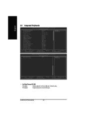
... Help F7: Optimized Defaults On-Chip Primary PCI IDE Enabled Enable onboard 1st channel IDE port. (Default value) Disabled Disable onboard 1st channel IDE port. GA-8I915GL-MF Motherboard - 36 -
... Help F7: Optimized Defaults On-Chip Primary PCI IDE Enabled Enable onboard 1st channel IDE port. (Default value) Disabled Disable onboard 1st channel IDE port. GA-8I915GL-MF Motherboard - 36 -

Manual
Page 38
.... Disabled Disable onboard Serial port 1. This function will automatically setup the port 2 address. Half IR Function Duplex Half. (Default value) Full IR Function Duplex Full. GA-8I915GL-MF Motherboard - 38 - Enabled Enable this function. Disable onboard Serial port 2. Normal Set onboard I/O chip UART to Normal Mode. (Default Value) ASKIR IrDA Set onboard I /O chip...
.... Disabled Disable onboard Serial port 1. This function will automatically setup the port 2 address. Half IR Function Duplex Half. (Default value) Full IR Function Duplex Full. GA-8I915GL-MF Motherboard - 38 - Enabled Enable this function. Disable onboard Serial port 2. Normal Set onboard I/O chip UART to Normal Mode. (Default Value) ASKIR IrDA Set onboard I /O chip...
Manual
Page 40
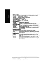
... the system. Enter Input password (from 1 to 5 characters to the Last state before AC-power off. If RTC Alarm Lead To Power On is Enabled. GA-8I915GL-MF Motherboard - 40 - English Resume by Alarm You can set "Resume by Keyboard" set at Password, you can set the password here. Disabled Enabled Disable this...
... the system. Enter Input password (from 1 to 5 characters to the Last state before AC-power off. If RTC Alarm Lead To Power On is Enabled. GA-8I915GL-MF Motherboard - 40 - English Resume by Alarm You can set "Resume by Keyboard" set at Password, you can set the password here. Disabled Enabled Disable this...