Manual
Page 4
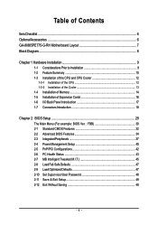
Table of Contents ItemChecklist ...6 OptionalAccessories ...6 GA-8I865PE775-G-RH Motherboard Layout 7 Block Diagram ...8 Chapter 1 Hardware Installation 9 1-1 Considerations Prior to Installation 9 1-2 Feature Summary 10 1-3 Installation of the CPU and CPU Cooler 12 1-3-1 Installation of the CPU 12 1-3-2 Installation of the Cooler 13 1-4 Installation of Memory 14 1-5 Installation of Expansion Cards 16 1-6 I/O Back Panel Introduction 17 1-7 Connectors Introduction 18 Chapter...
Table of Contents ItemChecklist ...6 OptionalAccessories ...6 GA-8I865PE775-G-RH Motherboard Layout 7 Block Diagram ...8 Chapter 1 Hardware Installation 9 1-1 Considerations Prior to Installation 9 1-2 Feature Summary 10 1-3 Installation of the CPU and CPU Cooler 12 1-3-1 Installation of the CPU 12 1-3-2 Installation of the Cooler 13 1-4 Installation of Memory 14 1-5 Installation of Expansion Cards 16 1-6 I/O Back Panel Introduction 17 1-7 Connectors Introduction 18 Chapter...

Manual
Page 8
Block Diagram AGP 8X/4X LGA775 Processor CPU CLK+/-(200/133 MHz) Host Interface Intel® 865G/865PE DDR 400/333/266 MHz DIMM Dual Channel Memory PCI Bus RTL 8110SC RJ45 Intel® ICH5 5 PCI PCI CLK (33 MHz) MIC Line-Out Line-In CODEC 8 USB Ports BIOS 2 Serial ATA ATA-33/66/100 IDE Channels IT8718 Floppy LPT Port COM Ports PS/2 KB/Mouse - 8 -
Block Diagram AGP 8X/4X LGA775 Processor CPU CLK+/-(200/133 MHz) Host Interface Intel® 865G/865PE DDR 400/333/266 MHz DIMM Dual Channel Memory PCI Bus RTL 8110SC RJ45 Intel® ICH5 5 PCI PCI CLK (33 MHz) MIC Line-Out Line-In CODEC 8 USB Ports BIOS 2 Serial ATA ATA-33/66/100 IDE Channels IT8718 Floppy LPT Port COM Ports PS/2 KB/Mouse - 8 -

Manual
Page 9
...the product, please verify that the power supply is best to wear an electrostatic discharge (ESD) cuff when handling electronic components (CPU, RAM). 4. Instances of uncertified components. 5. Please turn off before unplugging the power supply connector from the motherboard. Prior to... provided manual. 3. Damage as a result of an antistatic pad or within the computer casing. 6. Damage due to be an unofficial Gigabyte product. - 9 - Damage due to use of Non-Warranty 1. Damage due to use exceeding the permitted parameters. 6. Product determined to improper ...
...the product, please verify that the power supply is best to wear an electrostatic discharge (ESD) cuff when handling electronic components (CPU, RAM). 4. Instances of uncertified components. 5. Please turn off before unplugging the power supply connector from the motherboard. Prior to... provided manual. 3. Damage as a result of an antistatic pad or within the computer casing. 6. Damage due to be an unofficial Gigabyte product. - 9 - Damage due to use of Non-Warranty 1. Damage due to use exceeding the permitted parameters. 6. Product determined to improper ...
Manual
Page 10
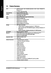
... / CoreTM 2 Duo / Pentium® D / Pentium® 4(Note 1) Š L2 cache varies with CPU Front Side Bus Š Supports 800/533 MHz FSB Chipset Š Northbridge:Intel® 865G/865PE Š Southbridge...CPU fan connector Š 1 system fan connector Š 1 front panel connector Š 1 front audio connector Š 1 CD In connector Š 1 AUX In connector Š 1 Surround Center connector Š 1 S/PDIF Out connector Š 1 power LED connector Š 2 USB 2.0/1.1 connectors for additional 4 ports by cables Š 1 Chassis Intrusion connector GA-8I865PE775-G-RH...
... / CoreTM 2 Duo / Pentium® D / Pentium® 4(Note 1) Š L2 cache varies with CPU Front Side Bus Š Supports 800/533 MHz FSB Chipset Š Northbridge:Intel® 865G/865PE Š Southbridge...CPU fan connector Š 1 system fan connector Š 1 front panel connector Š 1 front audio connector Š 1 CD In connector Š 1 AUX In connector Š 1 Surround Center connector Š 1 S/PDIF Out connector Š 1 power LED connector Š 2 USB 2.0/1.1 connectors for additional 4 ports by cables Š 1 Chassis Intrusion connector GA-8I865PE775-G-RH...

Manual
Page 11
... In) I/O Control Š IT8718 chip Hardware Monitor Š System voltage detection Š CPU temperature detection Š CPU / System fan speed detection Š CPU warning temperature Š CPU / System fan failure warning Š CPU smart fan control BIOS Š 1 4 Mbit flash ROM Š Use of licensed AWARD...Norton Internet Security (OEM version) Form Factor Š ATX form factor; 30.5cm x 21cm (Note 1) For further CPU support information, please go to GIGABYTE's website. (Note 2) Due to standard PC architecture, a certain amount of memory size will instead be shown as ...
... In) I/O Control Š IT8718 chip Hardware Monitor Š System voltage detection Š CPU temperature detection Š CPU / System fan speed detection Š CPU warning temperature Š CPU / System fan failure warning Š CPU smart fan control BIOS Š 1 4 Mbit flash ROM Š Use of licensed AWARD...Norton Internet Security (OEM version) Form Factor Š ATX form factor; 30.5cm x 21cm (Note 1) For further CPU support information, please go to GIGABYTE's website. (Note 2) Due to standard PC architecture, a certain amount of memory size will instead be shown as ...
Manual
Page 12
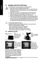
...meet the required standards for the peripherals. CPU: An Intel® Pentium 4 Processor with HT Technology - Fig. 2 Remove the plastic covering on the edge of the CPU socket. It is installed on the CPU socket to the CPU during installation.) GA-8I865PE775-G-RH Motherboard - 12 - Fig. 3 ...Notice the small gold colored triangle located on the CPU socket. Please take note of the one indented corner of ...
...meet the required standards for the peripherals. CPU: An Intel® Pentium 4 Processor with HT Technology - Fig. 2 Remove the plastic covering on the edge of the CPU socket. It is installed on the CPU socket to the CPU during installation.) GA-8I865PE775-G-RH Motherboard - 12 - Fig. 3 ...Notice the small gold colored triangle located on the CPU socket. Please take note of the one indented corner of ...
Manual
Page 13
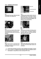
... as the picture, the installation is suggested that either thermal tape rather than heat paste be used for Intel boxed fan) Fig. 3 Place the CPU cooler atop the CPU and make sure the Male and Female push pin are joined closely. (for detailed installation instructions, please refer to the... an occurrence, it is complete. Fig. 6 Finally, please attach the power connector of the CPU cooler to the CPU cooler installation section of the user manual) Fig. 5 Please check the back of the heat paste. The CPU cooler may adhere to the pin hole on the motherboard.Pressing down the push pins...
... as the picture, the installation is suggested that either thermal tape rather than heat paste be used for Intel boxed fan) Fig. 3 Place the CPU cooler atop the CPU and make sure the Male and Female push pin are joined closely. (for detailed installation instructions, please refer to the... an occurrence, it is complete. Fig. 6 Finally, please attach the power connector of the CPU cooler to the CPU cooler installation section of the user manual) Fig. 5 Please check the back of the heat paste. The CPU cooler may adhere to the pin hole on the motherboard.Pressing down the push pins...

Manual
Page 19
... (Power Connector) With the use of the power connector, the power supply can lead to an unstable system or a system that is able to the CPU. If the ATX_12V power connector is not connected, the system will not start . If you use a power supply that is recommended that a power supply that...
... (Power Connector) With the use of the power connector, the power supply can lead to an unstable system or a system that is able to the CPU. If the ATX_12V power connector is not connected, the system will not start . If you use a power supply that is recommended that a power supply that...
Manual
Page 20
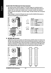
...a +12V power voltage. Before attaching the IDE cable, please take note of the foolproof groove in the IDE connector. 40 39 40 39 GA-8I865PE775-G-RH Motherboard 2 12 1 IDE1 IDE2 - 20 - Most coolers are designed with color-coded power connector wires. One IDE connector can connect to ...two IDE devices (hard drive or optical drive). Please remember to connect the CPU/system fan cable to the CPU_FAN/SYS_FAN connector to prevent the CPU/system from overheating and failure. 1 CPU_FAN CPU_FAN : Pin No. 1 2 3 4 Definition GND +12V / Speed...
...a +12V power voltage. Before attaching the IDE cable, please take note of the foolproof groove in the IDE connector. 40 39 40 39 GA-8I865PE775-G-RH Motherboard 2 12 1 IDE1 IDE2 - 20 - Most coolers are designed with color-coded power connector wires. One IDE connector can connect to ...two IDE devices (hard drive or optical drive). Please remember to connect the CPU/system fan cable to the CPU_FAN/SYS_FAN connector to prevent the CPU/system from overheating and failure. 1 CPU_FAN CPU_FAN : Pin No. 1 2 3 4 Definition GND +12V / Speed...

Manual
Page 31
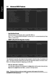
.... „ PC Health Status This setup page is the System auto detect Temperature, voltage, fan, speed. „ MB Intelligent Tweaker(M.I.T.) This setup page is control CPU clock and frequency ratio. „ Load Fail-Safe Defaults Fail-Safe Defaults indicates the value of the system parameters which the system would be in...
.... „ PC Health Status This setup page is the System auto detect Temperature, voltage, fan, speed. „ MB Intelligent Tweaker(M.I.T.) This setup page is control CPU clock and frequency ratio. „ Load Fail-Safe Defaults Fail-Safe Defaults indicates the value of the system parameters which the system would be in...

Manual
Page 33
No Errors The system boot will not stop for any error that has been installed in the CPU's memory address map. - 33 - Whenever the BIOS detects a non-fatal error the system will stop for systems with 640 K or more memory installed on the ...
No Errors The system boot will not stop for any error that has been installed in the CPU's memory address map. - 33 - Whenever the BIOS detects a non-fatal error the system will stop for systems with 640 K or more memory installed on the ...
Manual
Page 34
... cabling issue and report the approximate distance to the motherboard, the Status fields of all four pairs of the attached LAN cable. GA-8I865PE775-G-RH Motherboard - 34 - to move it down the list. Press to the following information for onboard(or add-on cards) SCSI,...wires will show Open and the Length fields show up , or to 3 (Note) No-Execute Memory Protect (Note) CPU Hyper-Threading (Note) CPU Enhanced Halt (C1E) (Note) CPU Thermal Monitor 2(TM2) (Note) CPU EIST Function (Note) Virtualization Technology(Note) [Press Enter] [Press Enter] [Floppy] [Hard Disk] [CDROM] [Setup...
... cabling issue and report the approximate distance to the motherboard, the Status fields of all four pairs of the attached LAN cable. GA-8I865PE775-G-RH Motherboard - 34 - to move it down the list. Press to the following information for onboard(or add-on cards) SCSI,...wires will show Open and the Length fields show up , or to 3 (Note) No-Execute Memory Protect (Note) CPU Hyper-Threading (Note) CPU Enhanced Halt (C1E) (Note) CPU Thermal Monitor 2(TM2) (Note) CPU EIST Function (Note) Virtualization Technology(Note) [Press Enter] [Press Enter] [Floppy] [Hard Disk] [CDROM] [Setup...

Manual
Page 36
... Enables CPU Hyper Threading Feature. CPU Thermal Monitor 2 (TM2) (Note) Enabled Enable CPU Thermal Monitor 2 (TM2) function. (Default value) Disabled Disable CPU Thermal Monitor 2 (TM2) function. GA-8I865PE775-G-RH Motherboard - 36 - Disables CPUID Limit for operating system with multi processors mode supported. CPU Enhanced Halt (C1E) (Note) Enabled Enable CPU Enhanced Halt (C1E) function. (Default value) Disabled Disable CPU Enhanced...
... Enables CPU Hyper Threading Feature. CPU Thermal Monitor 2 (TM2) (Note) Enabled Enable CPU Thermal Monitor 2 (TM2) function. (Default value) Disabled Disable CPU Thermal Monitor 2 (TM2) function. GA-8I865PE775-G-RH Motherboard - 36 - Disables CPUID Limit for operating system with multi processors mode supported. CPU Enhanced Halt (C1E) (Note) Enabled Enable CPU Enhanced Halt (C1E) function. (Default value) Disabled Disable CPU Enhanced...

Manual
Page 43
... Reset Case Open Status Case Opened Vcore DDR25V +3.3V +12V Current CPU Temperature Current CPU FAN Speed Current SYSTEM FAN Speed CPU Warning Temperature CPU FAN Fail Warning SYSTEM FAN Fail Warning CPU Smart FAN Control CPU Smart FAN Mode [Disabled] No OK OK OK OK 45oC 3245 RPM... / 194oF. Current Voltage(V) Vcore / DDR25V / +3.3V / +12V Detect system's voltage status automatically. Disabled Disable this function. (Default value) CPU/SYSTEM FAN Fail Warning Disabled Enabled Disable the fan fail warning function. (Default value) Enable the fan fail warning function. - 43 - Case Opened...
... Reset Case Open Status Case Opened Vcore DDR25V +3.3V +12V Current CPU Temperature Current CPU FAN Speed Current SYSTEM FAN Speed CPU Warning Temperature CPU FAN Fail Warning SYSTEM FAN Fail Warning CPU Smart FAN Control CPU Smart FAN Mode [Disabled] No OK OK OK OK 45oC 3245 RPM... / 194oF. Current Voltage(V) Vcore / DDR25V / +3.3V / +12V Detect system's voltage status automatically. Disabled Disable this function. (Default value) CPU/SYSTEM FAN Fail Warning Disabled Enabled Disable the fan fail warning function. (Default value) Enable the fan fail warning function. - 43 - Case Opened...

Manual
Page 44
Auto BIOS autodetects the type of CPU fan you installed and sets the optimal CPU Smart FAN control mode for CPU fans with Easy Tune based on CPU temperature. GA-8I865PE775-G-RH Motherboard - 44 - With such CPU fans, selecting PWM will run at different speed depending on their requirements. (Default Value) CPU Smart FAN Mode This option is available only...
Auto BIOS autodetects the type of CPU fan you installed and sets the optimal CPU Smart FAN control mode for CPU fans with Easy Tune based on CPU temperature. GA-8I865PE775-G-RH Motherboard - 44 - With such CPU fans, selecting PWM will run at different speed depending on their requirements. (Default Value) CPU Smart FAN Mode This option is available only...
Manual
Page 45
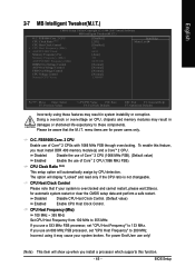
... 2-7 MB Intelligent Tweaker(M.I.T.) CMOS Setup Utility-Copyright (C) 1984-2007 Award Software MB Intelligent Tweaker(M.I .T. FSB1066 Core. 2 CPU CPU Clock Ratio (Note) CPU Host Clock Control x CPU Host Frequency (Mhz) x AGP/PCI/SRC Fixed Memory Frequency For Memory Frequency (Mhz) AGP/PCI/SRC Frequency (Mhz)... DIMM OverVoltage Control AGP OverVoltage Control FSB OverVoltage Control CPU Voltage Control Normal CPU Vcore [Disabled] [25X] [Disabled] 133 66/33 [Auto] 333 66/33/100 [Normal] [Normal] [Normal] [Normal] ...
... 2-7 MB Intelligent Tweaker(M.I.T.) CMOS Setup Utility-Copyright (C) 1984-2007 Award Software MB Intelligent Tweaker(M.I .T. FSB1066 Core. 2 CPU CPU Clock Ratio (Note) CPU Host Clock Control x CPU Host Frequency (Mhz) x AGP/PCI/SRC Fixed Memory Frequency For Memory Frequency (Mhz) AGP/PCI/SRC Frequency (Mhz)... DIMM OverVoltage Control AGP OverVoltage Control FSB OverVoltage Control CPU Voltage Control Normal CPU Vcore [Disabled] [25X] [Disabled] 133 66/33 [Auto] 333 66/33/100 [Normal] [Normal] [Normal] [Normal] ...

Manual
Page 46
... voltage, damage to +0.3V. English AGP/PCI/SRC Fixed This item will vary based on the CPU FSB. Memory Frequency For The adjustable range will be available when "CPU Host Clock Control" is very sensitive to boot. Memory Frequency (Mhz) The values depend on AGP...+0.3V. Normal Supply FSB voltage as AGP reauires. (Default value) +0.1V ~ +0.3V Increase AGP voltage by DRAM SPD data). GA-8I865PE775-G-RH Motherboard - 46 - Adjust AGP/PCI clock asychrohous with CPU. For power End-User use only! Default value: Auto (set to 2.0000V. (Default value: Normal) Normal...
... voltage, damage to +0.3V. English AGP/PCI/SRC Fixed This item will vary based on the CPU FSB. Memory Frequency For The adjustable range will be available when "CPU Host Clock Control" is very sensitive to boot. Memory Frequency (Mhz) The values depend on AGP...+0.3V. Normal Supply FSB voltage as AGP reauires. (Default value) +0.1V ~ +0.3V Increase AGP voltage by DRAM SPD data). GA-8I865PE775-G-RH Motherboard - 46 - Adjust AGP/PCI clock asychrohous with CPU. For power End-User use only! Default value: Auto (set to 2.0000V. (Default value: Normal) Normal...

Manual
Page 55
...6. Exit or Minimize button Description Enters the Overclocking setting page Enters the C.I .B. 3. for special enhancement for CPU and Memory, 3) Smart-Fan control for managing fan speed control of CPU frequency Shows the current functions status Log on different motherboards. - 55 - and M.I .A. PC Health 5....Toggles between Easy and Advance Mode Display panel of both CPU cooling fan and North-Bridge Chipset cooling fan, 4) PC health for enhancing system performance, 2) C.I .A. Featuring several powerful yet easy to GIGABYTE website Display EasyTuneTM 5 Help file Quit or Minimize ...
...6. Exit or Minimize button Description Enters the Overclocking setting page Enters the C.I .B. 3. for special enhancement for CPU and Memory, 3) Smart-Fan control for managing fan speed control of CPU frequency Shows the current functions status Log on different motherboards. - 55 - and M.I .A. PC Health 5....Toggles between Easy and Advance Mode Display panel of both CPU cooling fan and North-Bridge Chipset cooling fan, 4) PC health for enhancing system performance, 2) C.I .A. Featuring several powerful yet easy to GIGABYTE website Display EasyTuneTM 5 Help file Quit or Minimize ...


