Manual
Page 1
GA-8I865GME-775 Intel® Pentium® 4 LGA775 Processor Motherboard User's Manual Rev. 1002 12ME-865GMET-1002R * The WEEE marking on the product indicates this product must not be disposed of with user's other household waste and must be handed over to a designated collection point for the recycling of waste electrical and electronic equipment!! * The WEEE marking applies only in European Union's member states.
GA-8I865GME-775 Intel® Pentium® 4 LGA775 Processor Motherboard User's Manual Rev. 1002 12ME-865GMET-1002R * The WEEE marking on the product indicates this product must not be disposed of with user's other household waste and must be handed over to a designated collection point for the recycling of waste electrical and electronic equipment!! * The WEEE marking applies only in European Union's member states.
Manual
Page 2
Motherboard GA-8I865GME-775 Feb. 13, 2006 Motherboard GA-8I865GME-775 Feb. 13, 2006
Motherboard GA-8I865GME-775 Feb. 13, 2006 Motherboard GA-8I865GME-775 Feb. 13, 2006
Manual
Page 4
Table of Contents ItemChecklist ...6 GA-8I865GME-775 Motherboard Layout 7 Block Diagram ...8 Chapter 1 Hardware Installation 9 1-1 Considerations Prior to Installation 9 1-2 Feature Summary 10 1-3 Installation of the CPU and Heatsink 12 1-3-1 Installation of the CPU 12 1-3-2 ...
Table of Contents ItemChecklist ...6 GA-8I865GME-775 Motherboard Layout 7 Block Diagram ...8 Chapter 1 Hardware Installation 9 1-1 Considerations Prior to Installation 9 1-2 Feature Summary 10 1-3 Installation of the CPU and Heatsink 12 1-3-1 Installation of the CPU 12 1-3-2 ...
Manual
Page 7
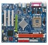
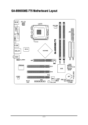
GA-8I865GME-775 Motherboard Layout KB_MS ATX_12V LGA775 CPU_FAN ATX VGA COMA LPT GA-8I865GME-775 DDR1 DDR2 IDE2 IDE1 R_USB USB_LAN IT8712 AUDIO F_AUDIO AGP EP82562G CODEC CD_IN Intel 865G SATA1 PCI1 CI ICH5 SATA0 PCI2 CLR_CMOS PCI3 BAT FDD BIOS F_USB1 PWR_LED SYS _FAN F_PANEL - 7 -
GA-8I865GME-775 Motherboard Layout KB_MS ATX_12V LGA775 CPU_FAN ATX VGA COMA LPT GA-8I865GME-775 DDR1 DDR2 IDE2 IDE1 R_USB USB_LAN IT8712 AUDIO F_AUDIO AGP EP82562G CODEC CD_IN Intel 865G SATA1 PCI1 CI ICH5 SATA0 PCI2 CLR_CMOS PCI3 BAT FDD BIOS F_USB1 PWR_LED SYS _FAN F_PANEL - 7 -
Manual
Page 9
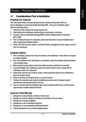
... there are required for warranty validation. 2. Damage due to be an unofficial Gigabyte product. - 9 - Instances of electrostatic discharge (ESD). Product determined to use exceeding the permitted parameters. 6. English Chapter 1 Hardware Installation 1-1 Considerations Prior to Installation Preparing Your Computer The motherboard contains numerous delicate electronic circuits and components which can lead to damage...
... there are required for warranty validation. 2. Damage due to be an unofficial Gigabyte product. - 9 - Instances of electrostatic discharge (ESD). Product determined to use exceeding the permitted parameters. 6. English Chapter 1 Hardware Installation 1-1 Considerations Prior to Installation Preparing Your Computer The motherboard contains numerous delicate electronic circuits and components which can lead to damage...
Manual
Page 10
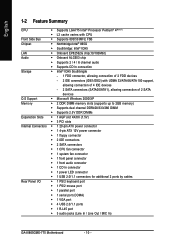
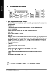
...; 1 parallel port Š 1 serial port (COMA) Š 1 VGA port Š 4 USB 2.0/1.1 ports Š 1 RJ-45 port Š 3 audio jacks (Line In / Line Out / MIC In) GA-8I865GME-775 Motherboard - 10 -
...; 1 parallel port Š 1 serial port (COMA) Š 1 VGA port Š 4 USB 2.0/1.1 ports Š 1 RJ-45 port Š 3 audio jacks (Line In / Line Out / MIC In) GA-8I865GME-775 Motherboard - 10 -
Manual
Page 11
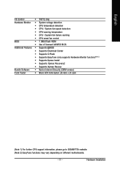
...; Norton Internet Security (OEM version) Form Factor Š Micro ATX form factor; 24.4cm x 21.2cm (Note 1) For further CPU support information, please go to GIGABYTE's website. (Note 2) EasyTune functions may vary depending on different motherboards. - 11 -
...; Norton Internet Security (OEM version) Form Factor Š Micro ATX form factor; 24.4cm x 21.2cm (Note 1) For further CPU support information, please go to GIGABYTE's website. (Note 2) EasyTune functions may vary depending on different motherboards. - 11 -
Manual
Page 12
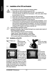
...computer system requires all of the following conditions: 1. Fig. 2 Remove the plastic covering on the CPU prior to the CPU during installation.) GA-8I865GME-775 Motherboard - 12 - Fig. 3 Notice the small gold colored triangle located on the CPU socket to your thumb and forefinger, carefully place it ...: An Intel® Chipset that supports HT Technology and has it enabled - Fig. 4 Once the CPU is not recommended that the motherboard supports the CPU. 2. Please make sure the heatsink is installed on the CPU socket. If you wish to set beyond the proper specifications...
...computer system requires all of the following conditions: 1. Fig. 2 Remove the plastic covering on the CPU prior to the CPU during installation.) GA-8I865GME-775 Motherboard - 12 - Fig. 3 Notice the small gold colored triangle located on the CPU socket to your thumb and forefinger, carefully place it ...: An Intel® Chipset that supports HT Technology and has it enabled - Fig. 4 Once the CPU is not recommended that the motherboard supports the CPU. 2. Please make sure the heatsink is installed on the CPU socket. If you wish to set beyond the proper specifications...
Manual
Page 13
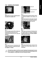
... arrow is to remove the heatsink, on the contrary, is to install.) Please note the direction of the heatsink to the pin hole on the motherboard.Pressing down the push pins diagonally. Fig. 6 Finally, please attach the power connector of arrow sign on the male push pin doesn't face inwards before...) Fig. 5 Please check the back of the installed CPU. Fig. 4 Please make sure the push pins aim to the CPU fan header located on the motherboard. English 1-3-2 Installation of the Heatsink Male Push Pin The top of Female Push Pin Female Push Pin Fig.1 Please apply an even layer of heatsink...
... arrow is to remove the heatsink, on the contrary, is to install.) Please note the direction of the heatsink to the pin hole on the motherboard.Pressing down the push pins diagonally. Fig. 6 Finally, please attach the power connector of arrow sign on the male push pin doesn't face inwards before...) Fig. 5 Please check the back of the installed CPU. Fig. 4 Please make sure the push pins aim to the CPU fan header located on the motherboard. English 1-3-2 Installation of the Heatsink Male Push Pin The top of Female Push Pin Female Push Pin Fig.1 Please apply an even layer of heatsink...
Manual
Page 14
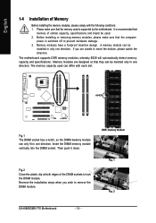
...Before installing the memory modules, please comply with each slot. English 1-4 Installation of the DIMM sockets to lock the DIMM module. The motherboard supports DDR memory modules, whereby BIOS will automatically detect memory capacity and specifications. The memory capacity used . 2. Reverse the installation steps ...the computer power is switched off to insert the module, please switch the direction. DDR memory module Fig. 1 Fig. 2 GA-8I865GME-775 Motherboard - 14 - notch Fig.1 The DIMM socket has a notch, so the DIMM memory module can be inserted only in one direction.
...Before installing the memory modules, please comply with each slot. English 1-4 Installation of the DIMM sockets to lock the DIMM module. The motherboard supports DDR memory modules, whereby BIOS will automatically detect memory capacity and specifications. The memory capacity used . 2. Reverse the installation steps ...the computer power is switched off to insert the module, please switch the direction. DDR memory module Fig. 1 Fig. 2 GA-8I865GME-775 Motherboard - 14 - notch Fig.1 The DIMM socket has a notch, so the DIMM memory module can be inserted only in one direction.
Manual
Page 15
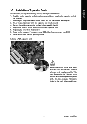
... slot bracket of the AGP slot when you try to the onboard AGP slot and press firmly down on the card are indeed seated in motherboard. 4. Make sure your expansion card by the small white-drawable bar. - 15 - Installing a AGP expansion card: Please carefully pull out the small whitedrawable bar at...
... slot bracket of the AGP slot when you try to the onboard AGP slot and press firmly down on the card are indeed seated in motherboard. 4. Make sure your expansion card by the small white-drawable bar. - 15 - Installing a AGP expansion card: Please carefully pull out the small whitedrawable bar at...
Manual
Page 16
...(s), please make sure your device(s) such as USB keyboard, mouse, scanner, zip, speaker...etc. have a standard USB interface. can be connected to MIC In jack. GA-8I865GME-775 Motherboard - 16 -
...(s), please make sure your device(s) such as USB keyboard, mouse, scanner, zip, speaker...etc. have a standard USB interface. can be connected to MIC In jack. GA-8I865GME-775 Motherboard - 16 -
Manual
Page 18
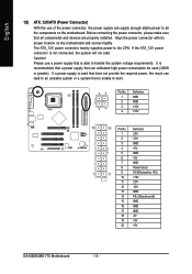
... 4 +5V 5 GND 6 +5V 7 GND 8 Power Good 1 11 9 5V SB (stand by +5V) 10 +12V 11 3.3V 12 -12V 13 GND 14 PS_ON(soft on the motherboard and connect tightly. Please use of the power connector, the power supply can lead to an unstable system or a system that is unable to start...! Align the power connector with its proper location on /off) 15 GND 16 GND 17 GND 18 -5V 19 +5V 20 +5V GA-8I865GME-775 Motherboard - 18 - If a power supply is used (300W or greater). If the ATX_12V power connector is not connected, the system will not start . 42 31 Pin ...
... 4 +5V 5 GND 6 +5V 7 GND 8 Power Good 1 11 9 5V SB (stand by +5V) 10 +12V 11 3.3V 12 -12V 13 GND 14 PS_ON(soft on the motherboard and connect tightly. Please use of the power connector, the power supply can lead to an unstable system or a system that is unable to start...! Align the power connector with its proper location on /off) 15 GND 16 GND 17 GND 18 -5V 19 +5V 20 +5V GA-8I865GME-775 Motherboard - 18 - If a power supply is used (300W or greater). If the ATX_12V power connector is not connected, the system will not start . 42 31 Pin ...
Manual
Page 20
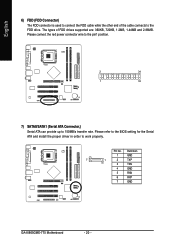
... for the Serial ATA and install the proper driver in order to 150MB/s transfer rate. Pin No. Definition 1 GND 7 1 2 TXP 3 TXN 4 GND 5 RXN 6 RXP 7 GND GA-8I865GME-775 Motherboard - 20 - Please connect the red power connector wire to the pin1 position. 2 34 1 33 7) SATA0/SATA1 (Serial ATA Connector,) Serial ATA can provide up to...
... for the Serial ATA and install the proper driver in order to 150MB/s transfer rate. Pin No. Definition 1 GND 7 1 2 TXP 3 TXN 4 GND 5 RXN 6 RXP 7 GND GA-8I865GME-775 Motherboard - 20 - Please connect the red power connector wire to the pin1 position. 2 34 1 33 7) SATA0/SATA1 (Serial ATA Connector,) Serial ATA can provide up to...
Manual
Page 22
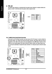
... same as the pin assigments on /off. Definition 1 MIC 2 GND 9 1 3 MIC_BIAS 4 POWER 10 2 5 FrontAudio(R) 6 Rear Audio (R)/ Return R 7 NC 8 No Pin 9 FrontAudio (L) 10 Rear Audio (L)/ Return L GA-8I865GME-775 Motherboard - 22 - It will blink when the system enters suspend mode.
... same as the pin assigments on /off. Definition 1 MIC 2 GND 9 1 3 MIC_BIAS 4 POWER 10 2 5 FrontAudio(R) 6 Rear Audio (R)/ Return R 7 NC 8 No Pin 9 FrontAudio (L) 10 Rear Audio (L)/ Return L GA-8I865GME-775 Motherboard - 22 - It will blink when the system enters suspend mode.
Manual
Page 24
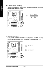
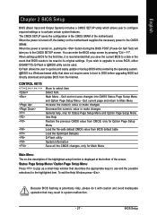
You can check the "Case Opened" status in BIOS Setup. 1 Pin No. To clear CMOS, temporarily short pins 1-2. To prevent improper use of this jumper. Definition 1 Signal 2 GND 14) CLR_CMOS (Clear CMOS) You may clear the CMOS data to detect if the chassis cover is removed. English 13) CI (Chassis Intrusion, Case Open) This 2-pin connector allows your system to its default values by this header, we do not include a jumper on it. 1 Open: Normal 1 Short: Clear CMOS GA-8I865GME-775 Motherboard - 24 -
You can check the "Case Opened" status in BIOS Setup. 1 Pin No. To clear CMOS, temporarily short pins 1-2. To prevent improper use of this jumper. Definition 1 Signal 2 GND 14) CLR_CMOS (Clear CMOS) You may clear the CMOS data to detect if the chassis cover is removed. English 13) CI (Chassis Intrusion, Case Open) This 2-pin connector allows your system to its default values by this header, we do not include a jumper on it. 1 Open: Normal 1 Short: Clear CMOS GA-8I865GME-775 Motherboard - 24 -
Manual
Page 27
...Q-Flash allows the user to quickly and easily update or backup BIOS without entering the operating system. @BIOS is displayed at the bottom of the motherboard. Status Page Setup Menu / Option Page Setup Menu Press to pop up BIOS for the highlighted item. Because BIOS flashing is recommended that you save...off, the battery on , pushing the button during the BIOS POST (Power-On Self Test) will take you wish to upgrade to a new BIOS, either GIGABYTE's Q-Flash or @BIOS utility can enter the BIOS setup screen by pressing "Ctrl + F1". If you to the CMOS SRAM. When setting up a ...
...Q-Flash allows the user to quickly and easily update or backup BIOS without entering the operating system. @BIOS is displayed at the bottom of the motherboard. Status Page Setup Menu / Option Page Setup Menu Press to pop up BIOS for the highlighted item. Because BIOS flashing is recommended that you save...off, the battery on , pushing the button during the BIOS POST (Power-On Self Test) will take you wish to upgrade to a new BIOS, either GIGABYTE's Q-Flash or @BIOS utility can enter the BIOS setup screen by pressing "Ctrl + F1". If you to the CMOS SRAM. When setting up a ...
Manual
Page 28
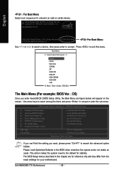
Press to exit this chapter are for reference only and may differ from the exact settings for your motherboard. GA-8I865GME-775 Motherboard - 28 - If you can't find the setting you enter Award BIOS CMOS Setup Utility, the Main Menu (as usual. Boot Menu == Select a Boot First..." to accept . The BIOS Setup menus described in the BIOS when somehow the system works not stable as figure below) will appear on cards) device. GA-8I865GME-775 D5 . . . . :BIOS Setup/Q-Flash, : Xpress Recovery2, For Boot Menu 01/27/2006-i865G-6A79AG0UC-00 For Boot Menu Use < > or < > to select a ...
Press to exit this chapter are for reference only and may differ from the exact settings for your motherboard. GA-8I865GME-775 Motherboard - 28 - If you can't find the setting you enter Award BIOS CMOS Setup Utility, the Main Menu (as usual. Boot Menu == Select a Boot First..." to accept . The BIOS Setup menus described in the BIOS when somehow the system works not stable as figure below) will appear on cards) device. GA-8I865GME-775 D5 . . . . :BIOS Setup/Q-Flash, : Xpress Recovery2, For Boot Menu 01/27/2006-i865G-6A79AG0UC-00 For Boot Menu Use < > or < > to select a ...
Manual
Page 30
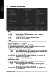
... faster system start up. The time is , , , . time clock. IDE Channel 0 Master/Slave ; IDE Channel 0 Master/Slave ; The four options are : Large/Auto(default:Auto) GA-8I865GME-775 Motherboard - 30 - English 2-1 Standard CMOS Features Date (mm:dd:yy) Time (hh:mm:ss) CMOS Setup Utility-Copyright (C) 1984-2006 Award Software Standard CMOS Features Wed...
... faster system start up. The time is , , , . time clock. IDE Channel 0 Master/Slave ; IDE Channel 0 Master/Slave ; The four options are : Large/Auto(default:Auto) GA-8I865GME-775 Motherboard - 30 - English 2-1 Standard CMOS Features Date (mm:dd:yy) Time (hh:mm:ss) CMOS Setup Utility-Copyright (C) 1984-2006 Award Software Standard CMOS Features Wed...
Manual
Page 31
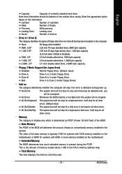
...keyboard or disk error; Extended Memory The BIOS determines how much extended memory is typically 512K for systems with 512K memory installed on the motherboard, or 640K for systems with 640K or more memory installed on this information. None No floppy drive installed 360K, 5.25" 5.25... Memory This item displays the memory size that has been installed in the CPU's memory address map. Enter the appropriate option based on the motherboard. Both Drive A & B are 3 mode Floppy Drives. All, But Keyboard The system boot will be labeled on The category determines whether...
...keyboard or disk error; Extended Memory The BIOS determines how much extended memory is typically 512K for systems with 512K memory installed on the motherboard, or 640K for systems with 640K or more memory installed on this information. None No floppy drive installed 360K, 5.25" 5.25... Memory This item displays the memory size that has been installed in the CPU's memory address map. Enter the appropriate option based on the motherboard. Both Drive A & B are 3 mode Floppy Drives. All, But Keyboard The system boot will be labeled on The category determines whether...


