
Manual
Page 4
Table of Contents GA-8AENXP-D Motherboard Layout 6 Block Diagram ...7 Chapter 1 Hardware Installation 9 1-1 Considerations Prior to Installation 9 1-2 Feature Summary 10 1-3 Installation of the CPU and Heatsink 12 1-3-1 Installation of the CPU 12 1-3-2 Installation of the Heatsink 13 1-4 Installing/Removing Cool-Plus (Northbridge Cooling Fan 14 1-5 Installation of Memory 14 1-6 Installation of Expansion Cards 16 1-7 I/O Back Panel Introduction 17 1-8 Connectors Introduction 18 Chapter 2 BIOS Setup 29 The Main Menu (For example: BIOS Ver. : F3d 30 2-1 Standard CMOS Features 32 ...
Table of Contents GA-8AENXP-D Motherboard Layout 6 Block Diagram ...7 Chapter 1 Hardware Installation 9 1-1 Considerations Prior to Installation 9 1-2 Feature Summary 10 1-3 Installation of the CPU and Heatsink 12 1-3-1 Installation of the CPU 12 1-3-2 Installation of the Heatsink 13 1-4 Installing/Removing Cool-Plus (Northbridge Cooling Fan 14 1-5 Installation of Memory 14 1-6 Installation of Expansion Cards 16 1-7 I/O Back Panel Introduction 17 1-8 Connectors Introduction 18 Chapter 2 BIOS Setup 29 The Main Menu (For example: BIOS Ver. : F3d 30 2-1 Standard CMOS Features 32 ...
Manual
Page 10
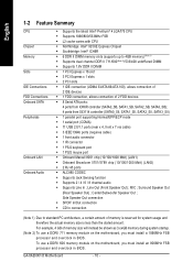
... port Š Onboard Marvell 8001 chip (10/100/1000 Mbit) (LAN1) Š Onboard Broadcom 5751/5789 chip (10/100/1000 Mbit) (LAN2) Š 2 RJ 45 ports Š ALC880 CODEC Š Supports Jack Sensing function Š Supports 2 / 4 / 6 / 8 channel audio Š Supports Line In ; To use a DDRII 711 memory module on the motherboard, you must install an 800MHz FSB processor and overclock in BIOS. English 1-2 Feature Summary CPU Chipset Memory Slots IDE Connections FDD Connections Onboard SATA Peripherals Onboard LAN Onboard Audio Š Supports...
... port Š Onboard Marvell 8001 chip (10/100/1000 Mbit) (LAN1) Š Onboard Broadcom 5751/5789 chip (10/100/1000 Mbit) (LAN2) Š 2 RJ 45 ports Š ALC880 CODEC Š Supports Jack Sensing function Š Supports 2 / 4 / 6 / 8 channel audio Š Supports Line In ; To use a DDRII 711 memory module on the motherboard, you must install an 800MHz FSB processor and overclock in BIOS. English 1-2 Feature Summary CPU Chipset Memory Slots IDE Connections FDD Connections Onboard SATA Peripherals Onboard LAN Onboard Audio Š Supports...

Manual
Page 11
... U-Plus DPS Š Supports @BIOS Overclocking Š Supports EasyTune 5 Š Over Voltage via BIOS (CPU/ DDR II/ PCI-E) Š Over Clock via BIOS (CPU/ DDR II/ PCI-E) Form Factor Š ATX form factor; 30.5cm x 24.4cm - 11 - English I/O Control Š IT8712 Hardware Monitor Š System voltage detection Š CPU temperature detection Š CPU / System / Power fan speed detection Š CPU warning temperature Š CPU / System / Power fan failure warning Š CPU smart fan control Onboard SATA RAID Š Onboard ICH6R chipset (SATA0_SB, SATA1_SB, SATA2_SB...
... U-Plus DPS Š Supports @BIOS Overclocking Š Supports EasyTune 5 Š Over Voltage via BIOS (CPU/ DDR II/ PCI-E) Š Over Clock via BIOS (CPU/ DDR II/ PCI-E) Form Factor Š ATX form factor; 30.5cm x 24.4cm - 11 - English I/O Control Š IT8712 Hardware Monitor Š System voltage detection Š CPU temperature detection Š CPU / System / Power fan speed detection Š CPU warning temperature Š CPU / System / Power fan failure warning Š CPU smart fan control Onboard SATA RAID Š Onboard ICH6R chipset (SATA0_SB, SATA1_SB, SATA2_SB...
Manual
Page 20
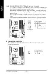
... GA-8AENXP-D Motherboard - 20 - The black connector wire is GND) 1 Pin No. Please remember to connect the power to the CPU fan to prevent system overheating and failure. Please remember to connect the power to the cooler to prevent CPU overheating and failure. 1 CPU_FAN Pin No. 1 2 3 4 1 SYS_FAN / PWR_FAN Definition GND +12V Sense Speed Control (Only for CPU_FAN) power connector and possesses a ful-proof connection design. Caution! English 3/4/5) CPU_FAN / SYS_FAN / PWR_FAN (Cooler Fan Power Connector...
... GA-8AENXP-D Motherboard - 20 - The black connector wire is GND) 1 Pin No. Please remember to connect the power to the CPU fan to prevent system overheating and failure. Please remember to connect the power to the cooler to prevent CPU overheating and failure. 1 CPU_FAN Pin No. 1 2 3 4 1 SYS_FAN / PWR_FAN Definition GND +12V Sense Speed Control (Only for CPU_FAN) power connector and possesses a ful-proof connection design. Caution! English 3/4/5) CPU_FAN / SYS_FAN / PWR_FAN (Cooler Fan Power Connector...
Manual
Page 21
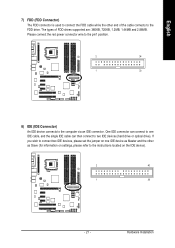
Hardware Installation The types of the cable connects to the instructions located on the IDE device). 2 40 1 39 - 21 - Please connect the red power connector wire to the pin1 position. 2 34 1 33 8) IDE (IDE Connector) An IDE device connects to two IDE devices (hard drive or optical drive). One IDE connector can then connect to the computer via an IDE connector. If you wish to connect two IDE devices, please set the jumper on one IDE cable, and the single IDE cable can connect to one IDE device as Slave (for...
Hardware Installation The types of the cable connects to the instructions located on the IDE device). 2 40 1 39 - 21 - Please connect the red power connector wire to the pin1 position. 2 34 1 33 8) IDE (IDE Connector) An IDE device connects to two IDE devices (hard drive or optical drive). One IDE connector can then connect to the computer via an IDE connector. If you wish to connect two IDE devices, please set the jumper on one IDE cable, and the single IDE cable can connect to one IDE device as Slave (for...
Manual
Page 22
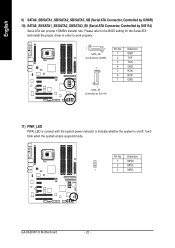
Please refer to the BIOS setting for the Serial ATA and install the proper driver in order to indicate whether the system is connect with the system power indicator to work properly. 1 7 SATA_SB (Controlled by ICH6R) 7 1 SATA_SII (Controlled by SiI3114) Serial ATA can provide 150MB/s transfer rate. Definition 1 MPD+ 2 MPD- 1 3 MPD- Pin No. English 9) SATA0_SB/SATA1_SB/SATA2_SB/SATA3_SB (Serial ATA Connector, Controlled by ICH6R) 10) SATA0_SII...
Please refer to the BIOS setting for the Serial ATA and install the proper driver in order to indicate whether the system is connect with the system power indicator to work properly. 1 7 SATA_SB (Controlled by ICH6R) 7 1 SATA_SII (Controlled by SiI3114) Serial ATA can provide 150MB/s transfer rate. Definition 1 MPD+ 2 MPD- 1 3 MPD- Pin No. English 9) SATA0_SB/SATA1_SB/SATA2_SB/SATA3_SB (Serial ATA Connector, Controlled by ICH6R) 10) SATA0_SII...
Manual
Page 29
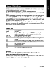
... you save changes into CMOS Status Page Setup Menu and Option Page Setup Menu - Status Page Setup Menu / Option Page Setup Menu Press F1 to a disk in the CMOS SRAM of the screen. You can be reset to DOS before upgrading BIOS but directly download and update BIOS from BIOS default table Load the Optimized Defaults Dual BIOS/Q-Flash utility System Information Save all the CMOS changes, only for the first time, it is displayed at the bottom of the motherboard. When setting up...
... you save changes into CMOS Status Page Setup Menu and Option Page Setup Menu - Status Page Setup Menu / Option Page Setup Menu Press F1 to a disk in the CMOS SRAM of the screen. You can be reset to DOS before upgrading BIOS but directly download and update BIOS from BIOS default table Load the Optimized Defaults Dual BIOS/Q-Flash utility System Information Save all the CMOS changes, only for the first time, it is displayed at the bottom of the motherboard. When setting up...
Manual
Page 32
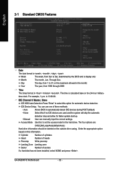
...:24 Item Help Menu Level` ` IDE Channel 0 Master ` IDE Channel 0 Slave [None] [None] Change the day, month, year Drive A Drive B Floppy 3 Mode Suport Halt On Base Memory Extended Memory Total Memory [1.44M, 3.5"] [None] [Disabled] [All, But Keyboard] 640K 511M 512M Sun. IDE Device Setup. Access Mode Use this option for automatic device detection. GA-8AENXP-D Motherboard - 32 - time clock. to set the access mode for faster system start up. • Manual User can use one of sectors If a hard disk has not been installed, select NONE and...
...:24 Item Help Menu Level` ` IDE Channel 0 Master ` IDE Channel 0 Slave [None] [None] Change the day, month, year Drive A Drive B Floppy 3 Mode Suport Halt On Base Memory Extended Memory Total Memory [1.44M, 3.5"] [None] [Disabled] [All, But Keyboard] 640K 511M 512M Sun. IDE Device Setup. Access Mode Use this option for automatic device detection. GA-8AENXP-D Motherboard - 32 - time clock. to set the access mode for faster system start up. • Manual User can use one of sectors If a hard disk has not been installed, select NONE and...
Manual
Page 37
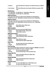
... Disabled Enable USB keyboard support. Onboard H/W SATA Enabled Enable onboard H/W SATA function. (Default value) Disabled Disable this function if you are not using onboard USB 2.0 feature. English Enhanced Set On-Chip SATA mode to Enhanced, the motherboard allows up to 6 HDDs to HD Audio. (Default value) Onboard H/W 1394 Enabled Disabled Enable onboard IEEE 1394 function. (Default value) Disable this function. Non-Combined Set On-Chip SATA mode to Non-Combined, SATA will auto set to AC97. Front Panel Type If you connect AC97 Audio Panel to the AZALIA_FP connector...
... Disabled Enable USB keyboard support. Onboard H/W SATA Enabled Enable onboard H/W SATA function. (Default value) Disabled Disable this function if you are not using onboard USB 2.0 feature. English Enhanced Set On-Chip SATA mode to Enhanced, the motherboard allows up to 6 HDDs to HD Audio. (Default value) Onboard H/W 1394 Enabled Disabled Enable onboard IEEE 1394 function. (Default value) Disable this function. Non-Combined Set On-Chip SATA mode to Non-Combined, SATA will auto set to AC97. Front Panel Type If you connect AC97 Audio Panel to the AZALIA_FP connector...

Manual
Page 42
... Monitor CPU temperature at next boot. English 2-6 PC Health Status CMOS Setup Utility-Copyright (C) 1984-2004 Award Software PC Health Status Reset Case Open Status Case Opened Vcore DDR18V +3.3V +12V Current CPU Temperature Current CPU FAN Speed Current POWER FAN Speed Current SYSTEM FAN Speed CPU Warning Temperature CPU FAN Fail Warning POWER FAN Fail Warning SYSTEM FAN Fail Warning CPU Smart FAN Control CPU Smart FAN Mode [Disabled] No OK OK OK OK 33oC 4687 RPM 0 RPM 0 RPM [Disabled] [Disabled] [Disabled] [Disabled] [Enabled] [Auto] Item Help Menu Level` KLJI: Move Enter: Select...
... Monitor CPU temperature at next boot. English 2-6 PC Health Status CMOS Setup Utility-Copyright (C) 1984-2004 Award Software PC Health Status Reset Case Open Status Case Opened Vcore DDR18V +3.3V +12V Current CPU Temperature Current CPU FAN Speed Current POWER FAN Speed Current SYSTEM FAN Speed CPU Warning Temperature CPU FAN Fail Warning POWER FAN Fail Warning SYSTEM FAN Fail Warning CPU Smart FAN Control CPU Smart FAN Mode [Disabled] No OK OK OK OK 33oC 4687 RPM 0 RPM 0 RPM [Disabled] [Disabled] [Disabled] [Disabled] [Enabled] [Auto] Item Help Menu Level` KLJI: Move Enter: Select...

Manual
Page 43
... specifications. Enabled Enable the CPU Smart FAN Control function. (Default value) a. b. When the CPU temperature is lower than 65 degrees Celsius, CPU fan will not effectively reduce the fan speed. - 43 - CPU Smart FAN Mode This option is available only when CPU Smart FAN Control is higher than 20 degrees Celsius, CPU fan will change depending on the actual CPU temperature. English CPU Smart FAN Control Disabled Disable this function. BIOS Setup c. Auto BIOS autodetects the type of CPU fan you use a CPU fan with a 4-pin fan power cable. PWM Set to Voltage...
... specifications. Enabled Enable the CPU Smart FAN Control function. (Default value) a. b. When the CPU temperature is lower than 65 degrees Celsius, CPU fan will not effectively reduce the fan speed. - 43 - CPU Smart FAN Mode This option is available only when CPU Smart FAN Control is higher than 20 degrees Celsius, CPU fan will change depending on the actual CPU temperature. English CPU Smart FAN Control Disabled Disable this function. BIOS Setup c. Auto BIOS autodetects the type of CPU fan you use a CPU fan with a 4-pin fan power cable. PWM Set to Voltage...
Manual
Page 47
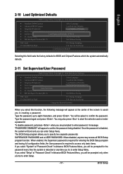
... confirm the password. Type the password, up to enter password. When disabled, anyone may also press to abort the selection and not enter a password. If you select "Setup" at the center of the screen to assist you in creating a password. English 2-10 Load Optimized Defaults CMOS Setup Utility-Copyright (C) 1984-2004 Award Software ` Standard CMOS Features Select Language ` Advanced BIOS Features Load Fail-Safe Defaults ` Integrated Peripherals Load Optimized Defaults ` Power Management Setup Set Supervisor Password ` PnP/PCI Configurations Load Optimized DefaultsS...
... confirm the password. Type the password, up to enter password. When disabled, anyone may also press to abort the selection and not enter a password. If you select "Setup" at the center of the screen to assist you in creating a password. English 2-10 Load Optimized Defaults CMOS Setup Utility-Copyright (C) 1984-2004 Award Software ` Standard CMOS Features Select Language ` Advanced BIOS Features Load Fail-Safe Defaults ` Integrated Peripherals Load Optimized Defaults ` Power Management Setup Set Supervisor Password ` PnP/PCI Configurations Load Optimized DefaultsS...

Manual
Page 55
... selecting from system over-enhancement by the user. Download Center Download Center allows users to be monitored and controlled via the Internet, C.O.M. to quickly download and update their BIOS as well as CPU, memory, graphics card, etc. Designed to the CPU for intelligent indication of all platform performance settings into different modes within BIOS setup in order to change BIOS feature settings with relative speed and ease. provides an immensely durable and...
... selecting from system over-enhancement by the user. Download Center Download Center allows users to be monitored and controlled via the Internet, C.O.M. to quickly download and update their BIOS as well as CPU, memory, graphics card, etc. Designed to the CPU for intelligent indication of all platform performance settings into different modes within BIOS setup in order to change BIOS feature settings with relative speed and ease. provides an immensely durable and...

Manual
Page 60
... Protection Disable Boot From Main Bios Auto Recovery Enable Halt On Error Disable Keep DMI Data Enable Copy Main ROM Data to Backup Load Default Settings Save Settings to CMOS Q-Flash Utility Update Main BIOS from Floppy Update Backup BIOS from Floppy Save Main BIOS to Floppy Save Backup BIOS to enter Flash utility. How to run stably as if nothing has happened in your PC will allow you to enter Award BIOS CMOS SETUP, then press to Floppy PgDn/PgUp: Modify : Move ESC: Reset 512K 512K F10: Power Off GA-8AENXP-D Motherboard - 60...
... Protection Disable Boot From Main Bios Auto Recovery Enable Halt On Error Disable Keep DMI Data Enable Copy Main ROM Data to Backup Load Default Settings Save Settings to CMOS Q-Flash Utility Update Main BIOS from Floppy Update Backup BIOS from Floppy Save Main BIOS to Floppy Save Backup BIOS to enter Flash utility. How to run stably as if nothing has happened in your PC will allow you to enter Award BIOS CMOS SETUP, then press to Floppy PgDn/PgUp: Modify : Move ESC: Reset 512K 512K F10: Power Off GA-8AENXP-D Motherboard - 60...

Manual
Page 61
... Setup of the BIOS Setting, if ACPI Suspend Type is on the boot screen, and the system will be set to the Backup BIOS. Copy Main ROM Data to Backup (If you want to enter the BIOS setting, please press "Del" key when the boot screen appears.) Halt On Error : Disable(Default), Enable If the BIOS occurs a checksum error or the Main BIOS occurs a WIDE RANGE PROTECTION error and Halt On Error set to RAM, the Auto Recovery will be replaced by user.) Load Default Settings Load dual BIOS default...
... Setup of the BIOS Setting, if ACPI Suspend Type is on the boot screen, and the system will be set to the Backup BIOS. Copy Main ROM Data to Backup (If you want to enter the BIOS setting, please press "Del" key when the boot screen appears.) Halt On Error : Disable(Default), Enable If the BIOS occurs a checksum error or the Main BIOS occurs a WIDE RANGE PROTECTION error and Halt On Error set to RAM, the Auto Recovery will be replaced by user.) Load Default Settings Load dual BIOS default...

Manual
Page 63
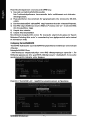
... Utility Boot From Main Bios Main ROM Type/Size SST 49LF004A Backup ROM Type/Size SST 49LF004A 512K 512K Wide Range Protection Disable Boot From Main Bios Auto Recovery Enable Halt On Error Disable Copy Main ROM Data to Backup Load Default Settings Save Settings to CMOS Q-Flash Utility Load Main BIOS from Floppy Load Backup BIOS from Floppy Save Main BIOS to Floppy Save Backup BIOS to enter BIOS menu. English Entering the Q-FlashTM utility: Step1: To use Q-Flash utility, you must press Del in the boot screen to Floppy Enter : Run :Move ESC:Reset F10:Power Off Dual BIOS utility...
... Utility Boot From Main Bios Main ROM Type/Size SST 49LF004A Backup ROM Type/Size SST 49LF004A 512K 512K Wide Range Protection Disable Boot From Main Bios Auto Recovery Enable Halt On Error Disable Copy Main ROM Data to Backup Load Default Settings Save Settings to CMOS Q-Flash Utility Load Main BIOS from Floppy Load Backup BIOS from Floppy Save Main BIOS to Floppy Save Backup BIOS to enter BIOS menu. English Entering the Q-FlashTM utility: Step1: To use Q-Flash utility, you must press Del in the boot screen to Floppy Enter : Run :Move ESC:Reset F10:Power Off Dual BIOS utility...
Manual
Page 66
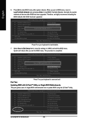
... Enter to load defaults. 7. Press Y on your keyboard to save the settings to CMOS and exit the BIOS menu. Press Del to CMOS and EXIT (SYe/tNS)u?pYervisor Password PnP/PCI Configurations Set User Password PC Health Status Save & Exit Setup MB Intelligent Tweaker(M.I.T.) Exit Without Saving ESC: Quit F8: Dual BIOS/Q-Flash F3: Change Language F10: Save & Exit Setup Time, Date, Hard Disk Type... This part guides users of single-BIOS motherboards how to save and exit. English 6. GA-8AENXP-D Motherboard...
... Enter to load defaults. 7. Press Y on your keyboard to save the settings to CMOS and exit the BIOS menu. Press Del to CMOS and EXIT (SYe/tNS)u?pYervisor Password PnP/PCI Configurations Set User Password PC Health Status Save & Exit Setup MB Intelligent Tweaker(M.I.T.) Exit Without Saving ESC: Quit F8: Dual BIOS/Q-Flash F3: Change Language F10: Save & Exit Setup Time, Date, Hard Disk Type... This part guides users of single-BIOS motherboards how to save and exit. English 6. GA-8AENXP-D Motherboard...
Manual
Page 72
.... Reset Disks to select Silicon Image). 5) Complete driver installation. 6) Complete RAID utility installation. Ctrl + S to Non-RAID 4. Note: To achieve best performance, it is provided. (For more detailed setup information, please visit "Support\ Motherboard\ Technology Guide section" on Integrated Peripherals). 4) Enter RAID setup in the BIOS and select the RAID type (For instance, enter Ctrl + I . The RAID prompt appears as Figure below to loading the OS. Physical Disks : Port Driver Model 0 ST3120026AS 1 ST3120026AS Serial # 3JT354CP 3JT329JX Size Type/Status...
.... Reset Disks to select Silicon Image). 5) Complete driver installation. 6) Complete RAID utility installation. Ctrl + S to Non-RAID 4. Note: To achieve best performance, it is provided. (For more detailed setup information, please visit "Support\ Motherboard\ Technology Guide section" on Integrated Peripherals). 4) Enter RAID setup in the BIOS and select the RAID type (For instance, enter Ctrl + I . The RAID prompt appears as Figure below to loading the OS. Physical Disks : Port Driver Model 0 ST3120026AS 1 ST3120026AS Serial # 3JT354CP 3JT329JX Size Type/Status...
Manual
Page 77
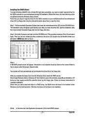
... and select MENU.exe (refer to Fig.1). (Note) (Note) Fig.1 Fig.2 Step 3: A MS-DOS prompt screen will then automatically zip and transfer this floppy disk. When install Windows 2000 or Windows XP from HDDs in the driver CD. English Installing the RAID drivers To install Windows 2000/XP onto a Serial ATA hard disk sucessfully, you have to copy the driver for the SATA controller on your motherboard during the Windows setup process. Your...
... and select MENU.exe (refer to Fig.1). (Note) (Note) Fig.1 Fig.2 Step 3: A MS-DOS prompt screen will then automatically zip and transfer this floppy disk. When install Windows 2000 or Windows XP from HDDs in the driver CD. English Installing the RAID drivers To install Windows 2000/XP onto a Serial ATA hard disk sucessfully, you have to copy the driver for the SATA controller on your motherboard during the Windows setup process. Your...

Manual
Page 83
...memory bad AWARD BIOS Beep Codes 1 short: System boots successfully 2 short: CMOS setting error 1 long 1 short: DRAM or M/B error 1 long 2 short: Monitor or display card error 1 long 3 short: Keyboard error 1 long 9 short: BIOS ROM error Continuous long beeps: DRAM error Continuous short beeps: Power error - 83 - Please refer to case. Questions 2: Why is the light of general asked questions based on a specific motherboard model, please log on power. 6. Turn off the on-board battery to leak voltage to makethem short for reference purposes. If your board has a Clear CMOS jumper...
...memory bad AWARD BIOS Beep Codes 1 short: System boots successfully 2 short: CMOS setting error 1 long 1 short: DRAM or M/B error 1 long 2 short: Monitor or display card error 1 long 3 short: Keyboard error 1 long 9 short: BIOS ROM error Continuous long beeps: DRAM error Continuous short beeps: Power error - 83 - Please refer to case. Questions 2: Why is the light of general asked questions based on a specific motherboard model, please log on power. 6. Turn off the on-board battery to leak voltage to makethem short for reference purposes. If your board has a Clear CMOS jumper...


