Manual
Page 1
GA-8AENXP-D Intel® Pentium® 4 LGA775 Processor Motherboard User's Manual Rev. 1004 12ME-8AENXPD-1004
GA-8AENXP-D Intel® Pentium® 4 LGA775 Processor Motherboard User's Manual Rev. 1004 12ME-8AENXPD-1004

Manual
Page 2
Motherboard GA-8AENXP-D Nov. 10, 2004 Motherboard GA-8AENXP-D Nov. 10, 2004
Motherboard GA-8AENXP-D Nov. 10, 2004 Motherboard GA-8AENXP-D Nov. 10, 2004

Manual
Page 4
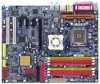
Table of Contents GA-8AENXP-D Motherboard Layout 6 Block Diagram ...7 Chapter 1 Hardware Installation 9 1-1 Considerations Prior to Installation 9 1-2 Feature Summary 10 1-3 Installation of the CPU and Heatsink 12 1-3-1 Installation of the CPU 12 1-3-2 ...
Table of Contents GA-8AENXP-D Motherboard Layout 6 Block Diagram ...7 Chapter 1 Hardware Installation 9 1-1 Considerations Prior to Installation 9 1-2 Feature Summary 10 1-3 Installation of the CPU and Heatsink 12 1-3-1 Installation of the CPU 12 1-3-2 ...
Manual
Page 7
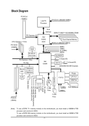
To use a DDRII 711 memory module on the motherboard, you must install an 800MHz FSB processor and overclock in BIOS. Block Diagram PCI-ECLK (100MHz) LGA775 Processor CPUCLK+/-(266/200/133MHz) PCI Express x16 3 .../Subwoofer Speaker Out Side Speaker Out MIC Line-Out Line-In SPDIF In SPDIF Out CY7C6564D (Note) To use a DDRII 600 memory module on the motherboard, you must install a 1066MHz FSB processor and overclock in BIOS. - 7 -
To use a DDRII 711 memory module on the motherboard, you must install an 800MHz FSB processor and overclock in BIOS. Block Diagram PCI-ECLK (100MHz) LGA775 Processor CPUCLK+/-(266/200/133MHz) PCI Express x16 3 .../Subwoofer Speaker Out Side Speaker Out MIC Line-Out Line-In SPDIF In SPDIF Out CY7C6564D (Note) To use a DDRII 600 memory module on the motherboard, you must install a 1066MHz FSB processor and overclock in BIOS. - 7 -

Manual
Page 9
Thus, prior to be an unofficial Gigabyte product. - 9 - Please do not remove the stickers on the motherboard. Instances of electrostatic discharge (ESD). Damage due to use exceeding the permitted parameters. 6. Installation Notices 1. ... installation, please follow the instructions below: 1. English Chapter 1 Hardware Installation 1-1 Considerations Prior to Installation Preparing Your Computer The motherboard contains numerous delicate electronic circuits and components which can lead to damage to improper installation. 4. Hardware Installation Please turn off before...
Thus, prior to be an unofficial Gigabyte product. - 9 - Please do not remove the stickers on the motherboard. Instances of electrostatic discharge (ESD). Damage due to use exceeding the permitted parameters. 6. Installation Notices 1. ... installation, please follow the instructions below: 1. English Chapter 1 Hardware Installation 1-1 Considerations Prior to Installation Preparing Your Computer The motherboard contains numerous delicate electronic circuits and components which can lead to damage to improper installation. 4. Hardware Installation Please turn off before...
Manual
Page 10
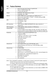
... Out ; Surround Speaker Out (Rear Speaker Out) ; Line Out (Front Speaker Out) ; To use a DDRII 711 memory module on the motherboard, you must install an 800MHz FSB processor and overclock in BIOS. Side Speaker Out connection Š SPDIF In/Out connection Š CD In connection... Š 1 FDD connection, allows connection of memory is reserved for system usage and therefore the actual memory size is less than the stated amount. GA-8AENXP-D Motherboard - 10 - MIC ; For example, 4 GB of memory size will instead be shown as 3.xxGB memory during system startup. (Note 2) To...
... Out ; Surround Speaker Out (Rear Speaker Out) ; Line Out (Front Speaker Out) ; To use a DDRII 711 memory module on the motherboard, you must install an 800MHz FSB processor and overclock in BIOS. Side Speaker Out connection Š SPDIF In/Out connection Š CD In connection... Š 1 FDD connection, allows connection of memory is reserved for system usage and therefore the actual memory size is less than the stated amount. GA-8AENXP-D Motherboard - 10 - MIC ; For example, 4 GB of memory size will instead be shown as 3.xxGB memory during system startup. (Note 2) To...
Manual
Page 12
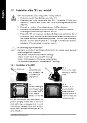
... the motherboard supports the CPU. 2. OS: An operation system that might cause damage to system use, otherwise overheating and permanent damage of Hyper-Threading Technology for HT Technology 1-3-1 Installation of the CPU Metal Lever Fig. 1 Gently lift the metal lever located on the CPU prior to the CPU during installation.) GA-8AENXP-D Motherboard - 12...
... the motherboard supports the CPU. 2. OS: An operation system that might cause damage to system use, otherwise overheating and permanent damage of Hyper-Threading Technology for HT Technology 1-3-1 Installation of the CPU Metal Lever Fig. 1 Gently lift the metal lever located on the CPU prior to the CPU during installation.) GA-8AENXP-D Motherboard - 12...

Manual
Page 13
..., it is complete. Fig. 6 Finally, please attach the power connector of the heatsink to the CPU fan header located on the surface of motherboard after installing. The heatsink may adhere to the CPU as the picture, the installation is suggested that either thermal tape rather than heat sink paste...the back of the installed CPU. Hardware Installation Fig. 2 (Turning the push pin along the direction of arrow is to the pin hole on the motherboard. Pressing down the push pins diagonally. Fig. 4 Please make sure the push pins aim to remove the heatsink, on the contrary, is only ...
..., it is complete. Fig. 6 Finally, please attach the power connector of the heatsink to the CPU fan header located on the surface of motherboard after installing. The heatsink may adhere to the CPU as the picture, the installation is suggested that either thermal tape rather than heat sink paste...the back of the installed CPU. Hardware Installation Fig. 2 (Turning the push pin along the direction of arrow is to the pin hole on the motherboard. Pressing down the push pins diagonally. Fig. 4 Please make sure the push pins aim to remove the heatsink, on the contrary, is only ...
Manual
Page 14
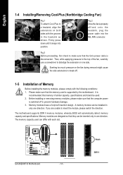
...align the extensions on the fan during removal might cause the side extensions to break-off to prevent hardware damage. 3. The motherboard supports DDR II memory modules, whereby BIOS will automatically detect memory capacity and specifications. The memory capacity used can be installed in... in the heatsink as shown. A memory module can differ with the grooves in one side. Memory modules have a foolproof insertion design. GA-8AENXP-D Motherboard - 14 - Fig.3 Before proceeding, first check to insert the module, please switch the direction. Firmly press down until it snaps into...
...align the extensions on the fan during removal might cause the side extensions to break-off to prevent hardware damage. 3. The motherboard supports DDR II memory modules, whereby BIOS will automatically detect memory capacity and specifications. The memory capacity used can be installed in... in the heatsink as shown. A memory module can differ with the grooves in one side. Memory modules have a foolproof insertion design. GA-8AENXP-D Motherboard - 14 - Fig.3 Before proceeding, first check to insert the module, please switch the direction. Firmly press down until it snaps into...

Manual
Page 16
... a PCI Express x 16 expansion card: Please carefully pull out the small whitedrawable bar at the end of expansion card from BIOS. 8. GA-8AENXP-D Motherboard - 16 - Press the expansion card firmly into the computer. 2. Power on the slot. Remove your computer's chassis cover. 7. Replace your computer's chassis cover, screws and ...
... a PCI Express x 16 expansion card: Please carefully pull out the small whitedrawable bar at the end of expansion card from BIOS. 8. GA-8AENXP-D Motherboard - 16 - Press the expansion card firmly into the computer. 2. Power on the slot. Remove your computer's chassis cover. 7. Replace your computer's chassis cover, screws and ...
Manual
Page 18
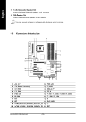
... / F_USB3 / F_USB4 6) NB_FAN 16) F1_1394 / F2_1394 7) FDD 17) IR 8) IDE 18) CLR_CMOS 9) SATA0_SB/SATA1_SB/SATA2_SB/SATA3_SB 19) CI 10) SATA0_SII/SATA1_SII/SATA2_SII/SATA3_SII 20) BAT GA-8AENXP-D Motherboard - 18 -
... / F_USB3 / F_USB4 6) NB_FAN 16) F1_1394 / F2_1394 7) FDD 17) IR 8) IDE 18) CLR_CMOS 9) SATA0_SB/SATA1_SB/SATA2_SB/SATA3_SB 19) CI 10) SATA0_SII/SATA1_SII/SATA2_SII/SATA3_SII 20) BAT GA-8AENXP-D Motherboard - 18 -

Manual
Page 19
... to start . Align the power connector with its proper location on the motherboard. Please use a 24-pin ATX power supply, please remove the small cover on the power connector on the motherboard before plugging in the power cord ; Hardware Installation Before connecting the power connector..., please make sure that all the components on the motherboard and connect tightly. Definition 13 1 1 3.3V 2 3.3V 3 GND 4 VCC 5 GND 6 VCC 7 GND 8 Power Good 9 5V SB(stand by +5V) 10...
... to start . Align the power connector with its proper location on the motherboard. Please use a 24-pin ATX power supply, please remove the small cover on the power connector on the motherboard before plugging in the power cord ; Hardware Installation Before connecting the power connector..., please make sure that all the components on the motherboard and connect tightly. Definition 13 1 1 3.3V 2 3.3V 3 GND 4 VCC 5 GND 6 VCC 7 GND 8 Power Good 9 5V SB(stand by +5V) 10...
Manual
Page 20
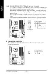
.... A red power connector wire indicates a positive connection and requires a +12V power voltage. Most coolers are designed with color-coded power connector wires. Definition 1 +12V 2 GND GA-8AENXP-D Motherboard - 20 - English 3/4/5) CPU_FAN / SYS_FAN / PWR_FAN (Cooler Fan Power Connector) The cooler fan power connector supplies a +12V power voltage via a 3-pin/4-pin(only for CPU_FAN) 6) NB_FAN...
.... A red power connector wire indicates a positive connection and requires a +12V power voltage. Most coolers are designed with color-coded power connector wires. Definition 1 +12V 2 GND GA-8AENXP-D Motherboard - 20 - English 3/4/5) CPU_FAN / SYS_FAN / PWR_FAN (Cooler Fan Power Connector) The cooler fan power connector supplies a +12V power voltage via a 3-pin/4-pin(only for CPU_FAN) 6) NB_FAN...
Manual
Page 22
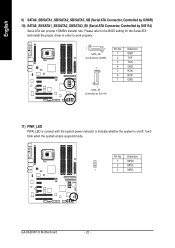
Definition 1 MPD+ 2 MPD- 1 3 MPD- Pin No. GA-8AENXP-D Motherboard - 22 - It will blink when the system enters suspend mode. Please refer to the BIOS setting for the Serial ATA and install the proper driver ...
Definition 1 MPD+ 2 MPD- 1 3 MPD- Pin No. GA-8AENXP-D Motherboard - 22 - It will blink when the system enters suspend mode. Please refer to the BIOS setting for the Serial ATA and install the proper driver ...

Manual
Page 24
... audio panel cable, incorrect connection between the cable and connector will make the device unable to the connector. 1 Pin No. Definition 1 CD-L 2 GND 3 GND 4 CD-R GA-8AENXP-D Motherboard - 24 - Definition Pin No. For optional audio panel cable, please contact your local dealer. English 13) AZALIA_FP (Front Audio Panel Connector) This connector is the...
... audio panel cable, incorrect connection between the cable and connector will make the device unable to the connector. 1 Pin No. Definition 1 CD-L 2 GND 3 GND 4 CD-R GA-8AENXP-D Motherboard - 24 - Definition Pin No. For optional audio panel cable, please contact your local dealer. English 13) AZALIA_FP (Front Audio Panel Connector) This connector is the...

Manual
Page 26
Please contact your nearest dealer for optional IR device. Pin No. Default doesn't include the "Shunter" to its default values by this jumper. Open: Normal 1 Short: Clear CMOS 1 GA-8AENXP-D Motherboard - 26 - To clear CMOS, temporarily short 1-2 pin. Definition 1 VCC 1 2 No Pin 3 IR RX 4 GND 5 IR TX 18) CLR_CMOS (Clear CMOS) You may clear the CMOS data to prevent from improper use this jumper. English 17) IR Be careful with the polarity of the IR connector while you connect the IR.
Please contact your nearest dealer for optional IR device. Pin No. Default doesn't include the "Shunter" to its default values by this jumper. Open: Normal 1 Short: Clear CMOS 1 GA-8AENXP-D Motherboard - 26 - To clear CMOS, temporarily short 1-2 pin. Definition 1 VCC 1 2 No Pin 3 IR RX 4 GND 5 IR TX 18) CLR_CMOS (Clear CMOS) You may clear the CMOS data to prevent from improper use this jumper. English 17) IR Be careful with the polarity of the IR connector while you connect the IR.

Manual
Page 28
English GA-8AENXP-D Motherboard - 28 -
English GA-8AENXP-D Motherboard - 28 -
Manual
Page 29
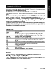
... Menu - The CMOS SETUP saves the configuration in the event that describes the appropriate keys to a disk in the CMOS SRAM of the motherboard. When setting up a small help , only for Status Page Setup Menu and Option Page Setup Menu Item Help Restore the previous CMOS value...you to be used. When the power is displayed at the bottom of the highlighted setup function is turned on the motherboard supplies the necessary power to a new BIOS, either GIGABYTE's Q-Flash or @BIOS utility can enter the BIOS setup screen by pressing "Ctrl + F1". CONTROL KEYS Move to...
... Menu - The CMOS SETUP saves the configuration in the event that describes the appropriate keys to a disk in the CMOS SRAM of the motherboard. When setting up a small help , only for Status Page Setup Menu and Option Page Setup Menu Item Help Restore the previous CMOS value...you to be used. When the power is displayed at the bottom of the highlighted setup function is turned on the motherboard supplies the necessary power to a new BIOS, either GIGABYTE's Q-Flash or @BIOS utility can enter the BIOS setup screen by pressing "Ctrl + F1". CONTROL KEYS Move to...

Manual
Page 30
... Defaults Set Supervisor Password Set User Password Save & Exit Setup Exit Without Saving F3: Change Language F10: Save & Exit Setup Time, Date, Hard Disk Type... GA-8AENXP-D Motherboard - 30 - Please Load Optimized Defaults in standard compatible BIOS. „ Advanced BIOS Features This setup page includes all the items of Award special enhanced features...
... Defaults Set Supervisor Password Set User Password Save & Exit Setup Exit Without Saving F3: Change Language F10: Save & Exit Setup Time, Date, Hard Disk Type... GA-8AENXP-D Motherboard - 30 - Please Load Optimized Defaults in standard compatible BIOS. „ Advanced BIOS Features This setup page includes all the items of Award special enhanced features...
Manual
Page 32
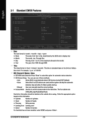
to Dec. 1 to 31 (or maximum allowed in . GA-8AENXP-D Motherboard - 32 - Through Dec. IDE Channel 0 Master, Slave IDE HDD Auto-Detection Press "Enter" to 2098 KLJI: Move Enter: Select +/-/PU/PD: Value F10: Save F3: ...
to Dec. 1 to 31 (or maximum allowed in . GA-8AENXP-D Motherboard - 32 - Through Dec. IDE Channel 0 Master, Slave IDE HDD Auto-Detection Press "Enter" to 2098 KLJI: Move Enter: Select +/-/PU/PD: Value F10: Save F3: ...


