Manual
Page 1
GA-880GMA-USB3 AM3+ socket motherboard for AMD AM3+ processor AMD AM3 Phenom™ II processor/ AMD Athlon™ II processor User's Manual Rev. 3101 12ME-88GMAB3-3101R
GA-880GMA-USB3 AM3+ socket motherboard for AMD AM3+ processor AMD AM3 Phenom™ II processor/ AMD Athlon™ II processor User's Manual Rev. 3101 12ME-88GMAB3-3101R

Manual
Page 3
...: For product-related information, check on our website at: http://www.gigabyte.com Identifying Your Motherboard Revision The revision number on your motherboard revision before updating motherboard BIOS, drivers, or when looking for technical information. Disclaimer Information in this : "REV: X.X." Copyright &#...; 2011 GIGA-BYTE TECHNOLOGY CO., LTD. Changes to their respective owners. For example, "REV: 1.0" means the revision of the motherboard is the property of this manual may be reproduced, copied, translated, transmitted, or published in the use of the product, read ...
...: For product-related information, check on our website at: http://www.gigabyte.com Identifying Your Motherboard Revision The revision number on your motherboard revision before updating motherboard BIOS, drivers, or when looking for technical information. Disclaimer Information in this : "REV: X.X." Copyright &#...; 2011 GIGA-BYTE TECHNOLOGY CO., LTD. Changes to their respective owners. For example, "REV: 1.0" means the revision of the motherboard is the property of this manual may be reproduced, copied, translated, transmitted, or published in the use of the product, read ...
Manual
Page 4
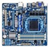
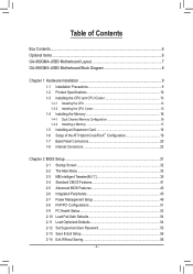
Table of Contents Box Contents...6 Optional Items...6 GA-880GMA-USB3 Motherboard Layout 7 GA-880GMA-USB3 Motherboard Block Diagram 8 Chapter 1 Hardware Installation 9 1-1 Installation Precautions 9 1-2 Product Specifications 10 1-3 Installing the CPU and CPU Cooler 13 1-3-1 Installing the CPU 13 1-3-2 Installing the CPU Cooler ...
Table of Contents Box Contents...6 Optional Items...6 GA-880GMA-USB3 Motherboard Layout 7 GA-880GMA-USB3 Motherboard Block Diagram 8 Chapter 1 Hardware Installation 9 1-1 Installation Precautions 9 1-2 Product Specifications 10 1-3 Installing the CPU and CPU Cooler 13 1-3-1 Installing the CPU 13 1-3-2 Installing the CPU Cooler ...
Manual
Page 6
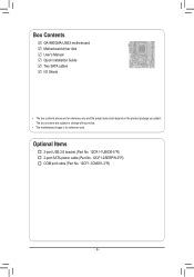
Box Contents GA-880GMA-USB3 motherboard Motherboard driver disk User's Manual Quick Installation Guide Two SATA cables I/O Shield • The box contents above are subject to change without notice. • The motherboard image is for reference only and the actual items shall depend on the product package you obtain. Optional Items 2-port USB 2.0 bracket (Part No. 12CR1-1UB030-5*R) 2-port SATA power cable (Part No. 12CF1-2SERPW-0*R) COM port cable (Part No. 12CF1-1CM001-3*R) - 6 - The box contents are for reference only.
Box Contents GA-880GMA-USB3 motherboard Motherboard driver disk User's Manual Quick Installation Guide Two SATA cables I/O Shield • The box contents above are subject to change without notice. • The motherboard image is for reference only and the actual items shall depend on the product package you obtain. Optional Items 2-port USB 2.0 bracket (Part No. 12CR1-1UB030-5*R) 2-port SATA power cable (Part No. 12CF1-2SERPW-0*R) COM port cable (Part No. 12CF1-1CM001-3*R) - 6 - The box contents are for reference only.
Manual
Page 8
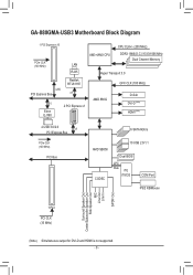
GA-880GMA-USB3 Motherboard Block Diagram 1 PCI Express x16 CPU CLK+/- (200 MHz) PCIe CLK (100 MHz) AM3+/AM3 CPU DDR3 1866(O.C.)/1333/1066 MHz Dual Channel Memory LAN ...
GA-880GMA-USB3 Motherboard Block Diagram 1 PCI Express x16 CPU CLK+/- (200 MHz) PCIe CLK (100 MHz) AM3+/AM3 CPU DDR3 1866(O.C.)/1333/1066 MHz Dual Channel Memory LAN ...
Manual
Page 9
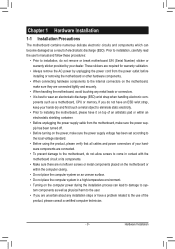
...have an ESD wrist strap, keep your hands dry and first touch a metal object to eliminate static electricity. • Prior to installing the motherboard, please have a problem related to the use of electrostatic discharge (ESD). ponents such as a result of the product, please consult a certified ...best to come in a high-temperature environment. • Turning on the computer power during the installation process can become damaged as a motherboard, CPU or memory. Prior to installation, carefully read the user's manual and follow these procedures: • Prior to installation, do not...
...have an ESD wrist strap, keep your hands dry and first touch a metal object to eliminate static electricity. • Prior to installing the motherboard, please have a problem related to the use of electrostatic discharge (ESD). ponents such as a result of the product, please consult a certified ...best to come in a high-temperature environment. • Turning on the computer power during the installation process can become damaged as a motherboard, CPU or memory. Prior to installation, carefully read the user's manual and follow these procedures: • Prior to installation, do not...
Manual
Page 12
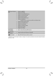
...;Š Support for Xpress Install ŠŠ Support for Xpress Recovery2 ŠŠ Support for EasyTune * Available functions in EasyTune may differ by motherboard model. ŠŠ Support for Easy Energy Saver ŠŠ Support for Smart Recovery ŠŠ Support for Auto Green ŠŠ Support...System ŠŠ Support for Microsoft® Windows 7/Vista/XP Form Factor ŠŠ Micro ATX Form Factor; 24.4cm x 23.4cm * GIGABYTE reserves the right to make any changes to the product specifications and product-related information without prior notice.
...;Š Support for Xpress Install ŠŠ Support for Xpress Recovery2 ŠŠ Support for EasyTune * Available functions in EasyTune may differ by motherboard model. ŠŠ Support for Easy Energy Saver ŠŠ Support for Smart Recovery ŠŠ Support for Auto Green ŠŠ Support...System ŠŠ Support for Microsoft® Windows 7/Vista/XP Form Factor ŠŠ Micro ATX Form Factor; 24.4cm x 23.4cm * GIGABYTE reserves the right to make any changes to the product specifications and product-related information without prior notice.
Manual
Page 13
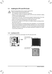
... socket.) • Apply an even and thin layer of thermal grease on the computer if the CPU cooler is not recommended that the motherboard supports the CPU. (Go to GIGABYTE's website for the peripherals. age of the Socket AM3+ Socket A Small Triangle Marking Denotes CPU Pin One AM3+/AM3 CPU - 13 - Locate...
... socket.) • Apply an even and thin layer of thermal grease on the computer if the CPU cooler is not recommended that the motherboard supports the CPU. (Go to GIGABYTE's website for the peripherals. age of the Socket AM3+ Socket A Small Triangle Marking Denotes CPU Pin One AM3+/AM3 CPU - 13 - Locate...

Manual
Page 14
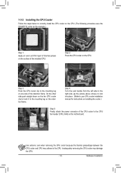
... incorrectly. CPU Socket Locking Lever Step 1: Completely lift up the CPU socket locking lever. Follow the steps below to correctly install the CPU into the motherboard CPU socket. • Before installing the CPU, make sure to turn off the computer and unplug the power cord from the power outlet to prevent...
... incorrectly. CPU Socket Locking Lever Step 1: Completely lift up the CPU socket locking lever. Follow the steps below to correctly install the CPU into the motherboard CPU socket. • Before installing the CPU, make sure to turn off the computer and unplug the power cord from the power outlet to prevent...
Manual
Page 15
...adhere to the CPU fan header (CPU_FAN) on the retention frame. Step 3: Hook the CPU cooler clip to the mounting lug on the motherboard. Step 2: Place the CPU cooler on the surface of the installed CPU. Hardware Installation 1-3-2 Installing the CPU Cooler Follow the steps below ...to correctly install the CPU cooler on the CPU. (The following procedure uses the GIGABYTE cooler as the picture above shows) to lock into place. (Refer to your CPU cooler installation manual for instructions on one side of...
...adhere to the CPU fan header (CPU_FAN) on the retention frame. Step 3: Hook the CPU cooler clip to the mounting lug on the motherboard. Step 2: Place the CPU cooler on the surface of the installed CPU. Hardware Installation 1-3-2 Installing the CPU Cooler Follow the steps below ...to correctly install the CPU cooler on the CPU. (The following procedure uses the GIGABYTE cooler as the picture above shows) to lock into place. (Refer to your CPU cooler installation manual for instructions on one side of...
Manual
Page 16
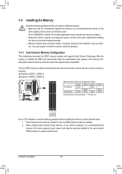
... that memory of the same capacity, brand, speed, and chips be used . (Go to GIGABYTE's website for optimum performance. After the memory is recommended that the motherboard supports the memory. DS/SS DS/SS DDR3_3 DS/SS - The four DDR3 memory sockets are...Double-Sided, "- -"=No Memory) DDR3_1 DDR3_2 DDR3_3 DDR3_4 Due to insert the memory, switch the direction. 1-4-1 Dual Channel Memory Configuration This motherboard provides four DDR3 memory sockets and supports Dual Channel Technology. Hardware Installation - 16 - 1-4 Installing the Memory Read the following guidelines before ...
... that memory of the same capacity, brand, speed, and chips be used . (Go to GIGABYTE's website for optimum performance. After the memory is recommended that the motherboard supports the memory. DS/SS DS/SS DDR3_3 DS/SS - The four DDR3 memory sockets are...Double-Sided, "- -"=No Memory) DDR3_1 DDR3_2 DDR3_3 DDR3_4 Due to insert the memory, switch the direction. 1-4-1 Dual Channel Memory Configuration This motherboard provides four DDR3 memory sockets and supports Dual Channel Technology. Hardware Installation - 16 - 1-4 Installing the Memory Read the following guidelines before ...

Manual
Page 17
... both ends of the memory, push down on the memory and insert it can only fit in one direction. Place the memory module on this motherboard. Hardware Installation Notch DDR3 DIMM A DDR3 memory module has a notch, so it vertically into place when the memory module is securely inserted. - 17 - Step 2: The...
... both ends of the memory, push down on the memory and insert it can only fit in one direction. Place the memory module on this motherboard. Hardware Installation Notch DDR3 DIMM A DDR3 memory module has a notch, so it vertically into place when the memory module is securely inserted. - 17 - Step 2: The...
Manual
Page 18
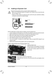
... turn off the computer and unplug the power cord from the power outlet before you begin to install an expansion card: • Make sure the motherboard supports the expansion card. Align the card with a screw. 5. Example: Installing and Removing a PCI Express Graphics Card: • Installing a Graphics Card: Gently push down on...
... turn off the computer and unplug the power cord from the power outlet before you begin to install an expansion card: • Make sure the motherboard supports the expansion card. Align the card with a screw. 5. Example: Installing and Removing a PCI Express Graphics Card: • Installing a Graphics Card: Gently push down on...

Manual
Page 19
...the Advanced BIOS Features menu: - Set Internal Graphics Mode to 256MB or 512MB. (Note 2) - D. An ATI Hybrid CrossFireX-supported motherboard and correct driver - Hardware Installation Windows 7/Vista operating system - Set UMA Frame Buffer Size to UMA. (Note 2) - Step 2: ...Plug the display cable into the onboard graphics port on the PCIEX16 slot. Configuring the Graphics Driver After installing the motherboard driver in "1-5 Installing an Expansion Card" and install an ATI Hybrid CrossFireX-supported graphics card on the back panel. A. ...
...the Advanced BIOS Features menu: - Set Internal Graphics Mode to 256MB or 512MB. (Note 2) - D. An ATI Hybrid CrossFireX-supported motherboard and correct driver - Hardware Installation Windows 7/Vista operating system - Set UMA Frame Buffer Size to UMA. (Note 2) - Step 2: ...Plug the display cable into the onboard graphics port on the PCIEX16 slot. Configuring the Graphics Driver After installing the motherboard driver in "1-5 Installing an Expansion Card" and install an ATI Hybrid CrossFireX-supported graphics card on the back panel. A. ...
Manual
Page 21
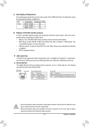
...Size (refer to the USB 2.0/1.1 specification. Use this port for video output: DVI-D, HDMI and D-Sub. Do not rock it straight out from the motherboard. • When removing the cable, pull it side to side to 1 Gbps data rate. RJ-45 LAN Port The Gigabit Ethernet LAN port provides Internet... Data transmission or receiving is occurring Off No data transmission or receiving is compatible to Chapter 2, "BIOS Setup," "Ad- A. Dual Display Configurations: This motherboard provides three ports for USB devices such as a USB keyboard/mouse, USB printer, USB flash drive and etc.
...Size (refer to the USB 2.0/1.1 specification. Use this port for video output: DVI-D, HDMI and D-Sub. Do not rock it straight out from the motherboard. • When removing the cable, pull it side to side to 1 Gbps data rate. RJ-45 LAN Port The Gigabit Ethernet LAN port provides Internet... Data transmission or receiving is occurring Off No data transmission or receiving is compatible to Chapter 2, "BIOS Setup," "Ad- A. Dual Display Configurations: This motherboard provides three ports for USB devices such as a USB keyboard/mouse, USB printer, USB flash drive and etc.

Manual
Page 23
... devices and your devices are compliant with the connectors you wish to connect. • Before installing the devices, be sure to the connector on the motherboard. - 23 - 1-8 Internal Connectors 13 7 8 10 2 4 5 9 11 12 6 1) ATX_12V 2) ATX 3) CPU_FAN 4) SYS_FAN 5) SATA3_0/1/2/3/4/5 6) F_PANEL 7) F_AUDIO 8) SPDIF_OUT 9) F_USB1/F_USB2/F_USB3 10) COM 11) BAT 12) CLR_CMOS Read...
... devices and your devices are compliant with the connectors you wish to connect. • Before installing the devices, be sure to the connector on the motherboard. - 23 - 1-8 Internal Connectors 13 7 8 10 2 4 5 9 11 12 6 1) ATX_12V 2) ATX 3) CPU_FAN 4) SYS_FAN 5) SATA3_0/1/2/3/4/5 6) F_PANEL 7) F_AUDIO 8) SPDIF_OUT 9) F_USB1/F_USB2/F_USB3 10) COM 11) BAT 12) CLR_CMOS Read...

Manual
Page 24
... is used (500W or greater). The power connector possesses a foolproof design. If the 12V power connector is turned off and all the components on the motherboard. 1/2) ATX_12V/ATX (2x4 12V Power Connector and 2x12 Main Power Connector) With the use of the power connector, the power supply can lead to an...
... is used (500W or greater). The power connector possesses a foolproof design. If the 12V power connector is turned off and all the components on the motherboard. 1/2) ATX_12V/ATX (2x4 12V Power Connector and 2x12 Main Power Connector) With the use of the power connector, the power supply can lead to an...

Manual
Page 25
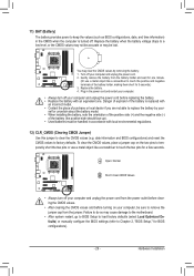
... drives. - 25 - The AMD SB850 south bridge supports RAID 0, RAID 1, RAID 5, RAID 10, and JBOD. The motherboard supports CPU fan speed control, which requires the use of hard drives does not have to your CPU and sysDtEeBmUGfrom oveDr-EBUG ...connect it is the ground wire). Definition 1 1 GND CPU_FAN 2 +12V /Speed Control 3 Sense 4 Speed Control SYS_FAN: Pin No. 3/4) CPU_FAN/SYS_FAN (Fan Headers) The motherboard has a 4-pin CPU fan header (CPU_FAN), a 4-pin system fan header (SYS_FAN). CPU_FAN: Pin No. SATA3_5 7 SATA3_3 7 SATA3_1 7 SATA3_4 1 SATA3_2 1 SATA3_0 1 ...
... drives. - 25 - The AMD SB850 south bridge supports RAID 0, RAID 1, RAID 5, RAID 10, and JBOD. The motherboard supports CPU fan speed control, which requires the use of hard drives does not have to your CPU and sysDtEeBmUGfrom oveDr-EBUG ...connect it is the ground wire). Definition 1 1 GND CPU_FAN 2 +12V /Speed Control 3 Sense 4 Speed Control SYS_FAN: Pin No. 3/4) CPU_FAN/SYS_FAN (Fan Headers) The motherboard has a 4-pin CPU fan header (CPU_FAN), a 4-pin system fan header (SYS_FAN). CPU_FAN: Pin No. SATA3_5 7 SATA3_3 7 SATA3_1 7 SATA3_4 1 SATA3_2 1 SATA3_0 1 ...

Manual
Page 27
... the HDMI display at the same time. You may require you to use a S/PDIF digital audio cable for digital audio output from your motherboard to your graphics card if you want to mute the back panel audio (only supported when using an HD front panel audio module), refer ...connectors on both of the front and back panel audio connections simultaneously. Incorrect connection between the module connector and the motherboard header will be present on each wire instead of the motherboard header. Pin No. For HD Front Panel Audio: For AC'97 Front Panel Audio: Pin No. Hardware ...
... the HDMI display at the same time. You may require you to use a S/PDIF digital audio cable for digital audio output from your motherboard to your graphics card if you want to mute the back panel audio (only supported when using an HD front panel audio module), refer ...connectors on both of the front and back panel audio connections simultaneously. Incorrect connection between the module connector and the motherboard header will be present on each wire instead of the motherboard header. Pin No. For HD Front Panel Audio: For AC'97 Front Panel Audio: Pin No. Hardware ...
Manual
Page 29
... the battery. 4. date information and BIOS configurations) and reset the CMOS values to Chapter 2, "BIOS Setup," for a few seconds. You may cause damage to the motherboard. • After system restart, go to BIOS Setup to load factory defaults (select Load Optimized Defaults) or manually configure the BIOS settings (refer to factory...
... the battery. 4. date information and BIOS configurations) and reset the CMOS values to Chapter 2, "BIOS Setup," for a few seconds. You may cause damage to the motherboard. • After system restart, go to BIOS Setup to load factory defaults (select Load Optimized Defaults) or manually configure the BIOS settings (refer to factory...


