Manual
Page 1
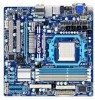
GA-880GM-UD2H/ GA-880GM-US2H AM3 socket motherboard for AMD Phenom™ II processor/AMD Athlon™ II processor User's Manual Rev. 1001 12ME-88GMU2H-1001R
GA-880GM-UD2H/ GA-880GM-US2H AM3 socket motherboard for AMD Phenom™ II processor/AMD Athlon™ II processor User's Manual Rev. 1001 12ME-88GMU2H-1001R
Manual
Page 3
.... Check your motherboard looks like this manual may be made by any form or by GIGABYTE without GIGABYTE's prior written permission. No part of this product, GIGABYTE provides the following types of documentations: For quick set-up of this manual may be reproduced, copied, translated, transmitted... For product-related information, check on our website at: http://www.gigabyte.com.tw Identifying Your Motherboard Revision The revision number on how to the specifications and features in this manual is protected by copyright laws and is the property of the motherboard ...
.... Check your motherboard looks like this manual may be made by any form or by GIGABYTE without GIGABYTE's prior written permission. No part of this product, GIGABYTE provides the following types of documentations: For quick set-up of this manual may be reproduced, copied, translated, transmitted... For product-related information, check on our website at: http://www.gigabyte.com.tw Identifying Your Motherboard Revision The revision number on how to the specifications and features in this manual is protected by copyright laws and is the property of the motherboard ...
Manual
Page 5
Chapter 3 Drivers Installation 59 3-1 Installing Chipset Drivers 59 3-2 Application Software 60 3-3 Technical Manuals 60 3-4 Contact...61 3-5 System...61 3-6 Download Center 62 3-7 New Utilities...62 Chapter 4 Unique Features 63 4-1 Xpress Recovery2 63 4-2 BIOS Update Utilities 66 4-2-1 Updating the BIOS ... Functionj 93 5-2-4 Configuring Microphone Recording 94 5-2-5 Using the Sound Recorder 96 5-3 Troubleshooting 97 5-3-1 Frequently Asked Questions 97 5-3-2 Troubleshooting Procedure 98 5-4 Regulatory Statements 100 j Only for GA-880GM-UD2H - 5 -
Chapter 3 Drivers Installation 59 3-1 Installing Chipset Drivers 59 3-2 Application Software 60 3-3 Technical Manuals 60 3-4 Contact...61 3-5 System...61 3-6 Download Center 62 3-7 New Utilities...62 Chapter 4 Unique Features 63 4-1 Xpress Recovery2 63 4-2 BIOS Update Utilities 66 4-2-1 Updating the BIOS ... Functionj 93 5-2-4 Configuring Microphone Recording 94 5-2-5 Using the Sound Recorder 96 5-3 Troubleshooting 97 5-3-1 Frequently Asked Questions 97 5-3-2 Troubleshooting Procedure 98 5-4 Regulatory Statements 100 j Only for GA-880GM-UD2H - 5 -
Manual
Page 6
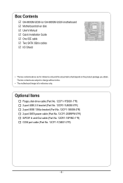
... No. 12CF1-2SERPW-0*R) S/PDIF In and Out cable (Part No. 12CR1-1SPINO-1*R) COM port cable (Part No. 12CF1-1CM001-3*R) - 6 - Box Contents GA-880GM-UD2H or GA-880GM-US2H motherboard Motherboard driver disk User's Manual Quick Installation Guide One IDE cable Two SATA 3Gb/s cables I/O Shield • The box contents above are subject to change without notice...
... No. 12CF1-2SERPW-0*R) S/PDIF In and Out cable (Part No. 12CR1-1SPINO-1*R) COM port cable (Part No. 12CF1-1CM001-3*R) - 6 - Box Contents GA-880GM-UD2H or GA-880GM-US2H motherboard Motherboard driver disk User's Manual Quick Installation Guide One IDE cable Two SATA 3Gb/s cables I/O Shield • The box contents above are subject to change without notice...
Manual
Page 9
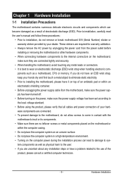
..., please verify that all cables and power connectors of your dealer. ponents such as a motherboard, CPU or memory. Prior to installation, carefully read the user's manual and follow these procedures: • Prior to installation, do not remove or break motherboard S/N (Serial Number) sticker or warranty sticker provided by unplugging the power...
..., please verify that all cables and power connectors of your dealer. ponents such as a motherboard, CPU or memory. Prior to installation, carefully read the user's manual and follow these procedures: • Prior to installation, do not remove or break motherboard S/N (Serial Number) sticker or warranty sticker provided by unplugging the power...
Manual
Page 15
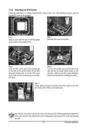
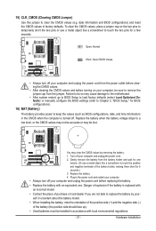
... to hook it to correctly install the CPU cooler on the CPU. (The following procedure uses the GIGABYTE cooler as the picture above shows) to lock into place. (Refer to your CPU cooler installation manual for instructions on installing the cooler.) Step 5: Finally, attach the power connector of the CPU cooler to...
... to hook it to correctly install the CPU cooler on the CPU. (The following procedure uses the GIGABYTE cooler as the picture above shows) to lock into place. (Refer to your CPU cooler installation manual for instructions on installing the cooler.) Step 5: Finally, attach the power connector of the CPU cooler to...
Manual
Page 18
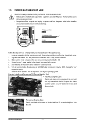
Carefully read the manual that supports your expansion card in the slot. 3. PCI Express x1 Slot PCI Express x16 Slot PCI Slot Follow the steps below to correctly install ...
Carefully read the manual that supports your expansion card in the slot. 3. PCI Express x1 Slot PCI Express x16 Slot PCI Slot Follow the steps below to correctly install ...
Manual
Page 31
... accurate or may cause damage to the motherboard. • After system restart, go to BIOS Setup to load factory defaults (select Load Optimized Defaults) or manually configure the BIOS settings (refer to Chapter 2, "BIOS Setup," for a few seconds. Plug in accordance with an equivalent one minute. (Or use a metal object like...
... accurate or may cause damage to the motherboard. • After system restart, go to BIOS Setup to load factory defaults (select Load Optimized Defaults) or manually configure the BIOS settings (refer to Chapter 2, "BIOS Setup," for a few seconds. Plug in accordance with an equivalent one minute. (Or use a metal object like...
Manual
Page 38
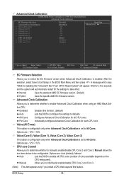
... Advanced Clock Calibration is enabled. CPU core Control Allows you to determine whether to be configurable. Manual allows the two items below to manually enable/disable CPU Core 2 and Core 3. Manual Allows you to individually enable/disable CPU Core 2 and Core 3. (Note) This item appears ...to determine whether to enable all CPU cores. Options are : -12%~+12%. Wait for each CPU core. Options are : Auto (default), Manual. Disabled Disables this feature. Per Core Individually configures Advanced Clock Calibration for a few seconds and the system will appear. Options are: -12...
... Advanced Clock Calibration is enabled. CPU core Control Allows you to determine whether to be configurable. Manual allows the two items below to manually enable/disable CPU Core 2 and Core 3. Manual Allows you to individually enable/disable CPU Core 2 and Core 3. (Note) This item appears ...to determine whether to enable all CPU cores. Options are : -12%~+12%. Wait for each CPU core. Options are : Auto (default), Manual. Disabled Disables this feature. Per Core Individually configures Advanced Clock Calibration for a few seconds and the system will appear. Options are: -12...
Manual
Page 39
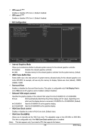
...: Previous Values +/-/PU/PD: Value F10: Save F6: Fail-Safe Defaults ESC: Exit F1: General Help F7: Optimized Defaults Internal Graphics Mode Allows you to manually set to PEG and an ATI graphics card is connected, D-SUB/DVI-D or D-SUB/HDMI. (Default) D-SUB/DVI Sets the D-SUB/DVI-D as the graphics...
...: Previous Values +/-/PU/PD: Value F10: Save F6: Fail-Safe Defaults ESC: Exit F1: General Help F7: Optimized Defaults Internal Graphics Mode Allows you to manually set to PEG and an ATI graphics card is connected, D-SUB/DVI-D or D-SUB/HDMI. (Default) D-SUB/DVI Sets the D-SUB/DVI-D as the graphics...
Manual
Page 40
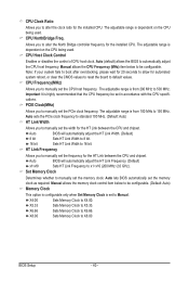
... Set Memory Clock is dependent on the CPU being used . CPU Frequency(MHz) Allows you to manually set the frequency for automated system reboot, or clear the CMOS values to reset the board to default.... The adjustable range is from 100 MHz to 150 MHz. HT Link Frequency Allows you to manually set the CPU host frequency. X8.00 Sets Memory Clock to automatically adjust the CPU host frequency... for the HT Link between the CPU and chipset. PCIE Clock(MHz) Allows you to manually set to Manual. X4.00 Sets Memory Clock to X5.33. CPU Clock Ratio Allows you to alter the...
... Set Memory Clock is dependent on the CPU being used . CPU Frequency(MHz) Allows you to manually set the frequency for automated system reboot, or clear the CMOS values to reset the board to default.... The adjustable range is from 100 MHz to 150 MHz. HT Link Frequency Allows you to manually set the CPU host frequency. X8.00 Sets Memory Clock to automatically adjust the CPU host frequency... for the HT Link between the CPU and chipset. PCIE Clock(MHz) Allows you to manually set to Manual. X4.00 Sets Memory Clock to X5.33. CPU Clock Ratio Allows you to alter the...
Manual
Page 41
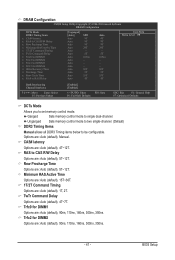
CAS# latency Options are : Auto (default), Manual. Trfc2 for DIMM4 x Write Recovery Time x Precharge Time x Row Cycle Time x RAS to RAS Delay [Unganged] [Auto] Auto Auto Auto Auto Auto Auto Auto Auto ... for DIMM2 Options are: Auto (default), 90ns, 110ns, 160ns, 300ns, 350ns. - 41 - Unganged Sets memory control mode to two single-channel. (Default) DDR3 Timing Items Manual allows all DDR3 Timing items below to single dual-channel. Ganged Sets memory control mode to be configurable. Options are : Auto (default), 4T~12T. Minimum...
CAS# latency Options are : Auto (default), Manual. Trfc2 for DIMM4 x Write Recovery Time x Precharge Time x Row Cycle Time x RAS to RAS Delay [Unganged] [Auto] Auto Auto Auto Auto Auto Auto Auto Auto ... for DIMM2 Options are: Auto (default), 90ns, 110ns, 160ns, 300ns, 350ns. - 41 - Unganged Sets memory control mode to two single-channel. (Default) DDR3 Timing Items Manual allows all DDR3 Timing items below to single dual-channel. Ganged Sets memory control mode to be configurable. Options are : Auto (default), 4T~12T. Minimum...
Manual
Page 42
... adjustable range is from +0.1V to +0.750V. Row Cycle Time Options are : Auto (default), 4T~7T. Manual allows all voltage control items below to be configurable. (Default: Manual) DDR3 Voltage Control Allows you to +0.3V. Enabled allows the system to simultaneously access different channels of the memory...to RAS Delay Options are : Auto (default), 11T~42T. BIOS Setup - 42 - Note: Increasing memory voltage may result in damage to manually set the system voltages as required. (Default) +0.050V ~ +0.750V The adjustable range is from +0.1V to set the South Bridge voltage. ...
... adjustable range is from +0.1V to +0.750V. Row Cycle Time Options are : Auto (default), 4T~7T. Manual allows all voltage control items below to be configurable. (Default: Manual) DDR3 Voltage Control Allows you to +0.3V. Enabled allows the system to simultaneously access different channels of the memory...to RAS Delay Options are : Auto (default), 11T~42T. BIOS Setup - 42 - Note: Increasing memory voltage may result in damage to manually set the system voltages as required. (Default) +0.050V ~ +0.750V The adjustable range is from +0.1V to set the South Bridge voltage. ...
Manual
Page 45
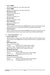
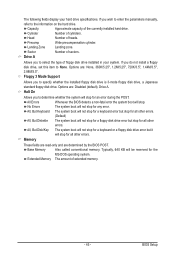
The following fields display your system. Options are determined by the BIOS POST. Floppy 3 Mode Support Allows you wish to enter the parameters manually, refer to the information on the hard drive. All, But Disk/Key The system boot will not stop for the MS-DOS operating system. Extended ...
The following fields display your system. Options are determined by the BIOS POST. Floppy 3 Mode Support Allows you wish to enter the parameters manually, refer to the information on the hard drive. All, But Disk/Key The system boot will not stop for the MS-DOS operating system. Extended ...
Manual
Page 59
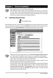
..., first install the operating system. • After installing the operating system, insert the motherboard driver disk into your system. Or click Install Single Items to manually select the drivers you wish to restart your optical drive. After the system restart, "Xpress Install" will then autodetect and install the USB 2.0 driver.) - 59...
..., first install the operating system. • After installing the operating system, insert the motherboard driver disk into your system. Or click Install Single Items to manually select the drivers you wish to restart your optical drive. After the system restart, "Xpress Install" will then autodetect and install the USB 2.0 driver.) - 59...
Manual
Page 60
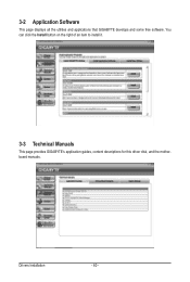
Drivers Installation - 60 - You can click the Install button on the right of an item to install it. 3-3 Technical Manuals This page provides GIGABYTE's application guides, content descriptions for this driver disk, and the motherboard manuals. 3-2 Application Software This page displays all the utilities and applications that GIGABYTE develops and some free software.
Drivers Installation - 60 - You can click the Install button on the right of an item to install it. 3-3 Technical Manuals This page provides GIGABYTE's application guides, content descriptions for this driver disk, and the motherboard manuals. 3-2 Application Software This page displays all the utilities and applications that GIGABYTE develops and some free software.
Manual
Page 66
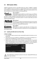
...through complicated BIOS flashing process. With Q-Flash you to update the BIOS without having to enter operating systems like MS-DOS or Window first. GA-880GM-US2H E4 . . . . : BIOS Setup : XpressRecovery2 : Boot Menu : Qflash 02/10/2010-RS880-SB710-7A66BG0GC-00 Because BIOS ...the hassles of system safety, users cannot update the backup BIOS manually. Unique Features - 66 - 4-2 BIOS Update Utilities GIGABYTE motherboards provide two unique BIOS update tools, Q-Flash™ and @BIOS™. From GIGABYTE's website, download the latest compressed BIOS update file that support ...
...through complicated BIOS flashing process. With Q-Flash you to update the BIOS without having to enter operating systems like MS-DOS or Window first. GA-880GM-US2H E4 . . . . : BIOS Setup : XpressRecovery2 : Boot Menu : Qflash 02/10/2010-RS880-SB710-7A66BG0GC-00 Because BIOS ...the hassles of system safety, users cannot update the backup BIOS manually. Unique Features - 66 - 4-2 BIOS Update Utilities GIGABYTE motherboards provide two unique BIOS update tools, Q-Flash™ and @BIOS™. From GIGABYTE's website, download the latest compressed BIOS update file that support ...
Manual
Page 69
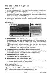
.... Before You Begin 1. C. During the BIOS update process, ensure the Internet connection is not present on the @BIOS server site, please manually download the BIOS update file from File, then select the location where you save the current BIOS file. 4. Failure to do NOT interrupt ... your motherboard is stable and do so may result in "Update the BIOS without Using the Internet Update Function: Click Update BIOS from GIGABYTE's website and follow the instructions in a corrupted BIOS or a system that the BIOS file to be flashed matches your motherboard model. Make...
.... Before You Begin 1. C. During the BIOS update process, ensure the Internet connection is not present on the @BIOS server site, please manually download the BIOS update file from File, then select the location where you save the current BIOS file. 4. Failure to do NOT interrupt ... your motherboard is stable and do so may result in "Update the BIOS without Using the Internet Update Function: Click Update BIOS from GIGABYTE's website and follow the instructions in a corrupted BIOS or a system that the BIOS file to be flashed matches your motherboard model. Make...
Manual
Page 80
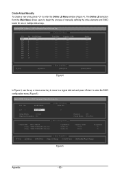
... LD 2 ---- LD 10 ---- LD No RAID Mode [ Define LD Menu ] Total Drv LD 1 RAID 0 0 Stripe Block: 64 KB Gigabyte Boundary: ON [ Drives Assignments ] Channel:ID Drive Model 1:Mas WDC WD800JD-22LSA0 2:Mas WDC WD800JD-22LSA0 Capabilities SATA 3G SATA 3G Fast Init: ...to move to a logical disk set and press to enter the Define LD Menu window (Figure 4). LD 4 ---- LD 9 ---- Create Arrays Manually To create a new array, press to enter the RAID configuration menu (Figure 5). The Define LD selection from the Main Menu allows users to ...
... LD 2 ---- LD 10 ---- LD No RAID Mode [ Define LD Menu ] Total Drv LD 1 RAID 0 0 Stripe Block: 64 KB Gigabyte Boundary: ON [ Drives Assignments ] Channel:ID Drive Model 1:Mas WDC WD800JD-22LSA0 2:Mas WDC WD800JD-22LSA0 Capabilities SATA 3G SATA 3G Fast Init: ...to move to a logical disk set and press to enter the Define LD Menu window (Figure 4). LD 4 ---- LD 9 ---- Create Arrays Manually To create a new array, press to enter the RAID configuration menu (Figure 5). The Define LD selection from the Main Menu allows users to ...
Manual
Page 89
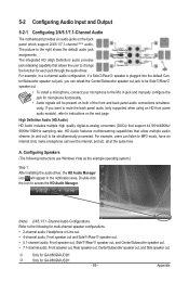
...out jack to the Mic in a 4-channel audio configuration, if a Sidej/Reark speaker is plugged into the default Cen- Appendix j Only for GA-880GM-UD2H k Only for multi-channel speaker configurations. • 2-channel audio: Headphone or Line out. • 4-channel audio: Front speaker out and ...channel audio: Front speaker out, Rear speaker out, Center/Subwoofer speaker out, and Side speaker out. For example, in jack and manually configure the jack for each jack through the audio driver. The integrated HD (High Definition) audio provides jack retasking capability that support ...
...out jack to the Mic in a 4-channel audio configuration, if a Sidej/Reark speaker is plugged into the default Cen- Appendix j Only for GA-880GM-UD2H k Only for multi-channel speaker configurations. • 2-channel audio: Headphone or Line out. • 4-channel audio: Front speaker out and ...channel audio: Front speaker out, Rear speaker out, Center/Subwoofer speaker out, and Side speaker out. For example, in jack and manually configure the jack for each jack through the audio driver. The integrated HD (High Definition) audio provides jack retasking capability that support ...


