
Manual
Page 4
... Motherboard Layout 7 GA-880G-USB3 Motherboard Block Diagram 8 Chapter 1 Hardware Installation 9 1-1 Installation Precautions 9 1-2 Product Specifications 10 1-3 Installing the CPU and CPU Cooler 13 1-3-1 Installing the CPU 13 1-3-2 Installing the CPU Cooler 15 1-4 Installing the Memory 16 1-4-1 Dual Channel Memory Configuration 16 1-4-2 Installing a Memory 17 1-5 Installing an Expansion Card 18 1-6 Setup of the ATI Hybrid CrossFireX™ Configuration 19 1-7 Back Panel Connectors 20 1-8 Internal Connectors 23 Chapter 2 BIOS Setup 31 2-1 Startup Screen 32 2-2 The Main Menu...
... Motherboard Layout 7 GA-880G-USB3 Motherboard Block Diagram 8 Chapter 1 Hardware Installation 9 1-1 Installation Precautions 9 1-2 Product Specifications 10 1-3 Installing the CPU and CPU Cooler 13 1-3-1 Installing the CPU 13 1-3-2 Installing the CPU Cooler 15 1-4 Installing the Memory 16 1-4-1 Dual Channel Memory Configuration 16 1-4-2 Installing a Memory 17 1-5 Installing an Expansion Card 18 1-6 Setup of the ATI Hybrid CrossFireX™ Configuration 19 1-7 Back Panel Connectors 20 1-8 Internal Connectors 23 Chapter 2 BIOS Setup 31 2-1 Startup Screen 32 2-2 The Main Menu...
Manual
Page 5
... Application Software 58 3-3 Technical Manuals 58 3-4 Contact...59 3-5 System...59 3-6 Download Center 60 3-7 New Utilities...60 Chapter 4 Unique Features 61 4-1 Xpress Recovery2 61 4-2 BIOS Update Utilities 64 4-2-1 Updating the BIOS with the Q-Flash Utility 64 4-2-2 Updating the BIOS with the @BIOS Utility 67 4-3 EasyTune 6...68 4-4 Easy Energy Saver 69 4-5 Q-Share...71 4-6 SMART Recovery 72 4-7 Auto Green...73 4-8 Cloud OC...74 Chapter 5 Appendix...75 5-1 Configuring SATA Hard Drive(s 75 5-1-1 Configuring the Onboard SATA Controller 75 5-1-2 Installing the SATA RAID/AHCI Driver...
... Application Software 58 3-3 Technical Manuals 58 3-4 Contact...59 3-5 System...59 3-6 Download Center 60 3-7 New Utilities...60 Chapter 4 Unique Features 61 4-1 Xpress Recovery2 61 4-2 BIOS Update Utilities 64 4-2-1 Updating the BIOS with the Q-Flash Utility 64 4-2-2 Updating the BIOS with the @BIOS Utility 67 4-3 EasyTune 6...68 4-4 Easy Energy Saver 69 4-5 Q-Share...71 4-6 SMART Recovery 72 4-7 Auto Green...73 4-8 Cloud OC...74 Chapter 5 Appendix...75 5-1 Configuring SATA Hard Drive(s 75 5-1-1 Configuring the Onboard SATA Controller 75 5-1-2 Installing the SATA RAID/AHCI Driver...

Manual
Page 10
... one PCI Express graphics card is to be installed, be less than 4 GB of physical memory is populated with the PCIEX4 slot. AMD AM3 Phenom™ II processor/ AMD Athlon™ II processor (Go to GIGABYTE's website for the latest CPU support list.) Hyper Transport Bus ŠŠ 5200 MT/s Chipset ŠŠ North Bridge: AMD 880G ŠŠ South Bridge: AMD SB710 Memory ŠŠ 4 x 1.5V DDR3 DIMM sockets supporting up to GIGABYTE...
... one PCI Express graphics card is to be installed, be less than 4 GB of physical memory is populated with the PCIEX4 slot. AMD AM3 Phenom™ II processor/ AMD Athlon™ II processor (Go to GIGABYTE's website for the latest CPU support list.) Hyper Transport Bus ŠŠ 5200 MT/s Chipset ŠŠ North Bridge: AMD 880G ŠŠ South Bridge: AMD SB710 Memory ŠŠ 4 x 1.5V DDR3 DIMM sockets supporting up to GIGABYTE...

Manual
Page 18
... in the expansion slot. 1. PCI Express x1 Slot PCI Express x16 Slot (PCIEX16) PCI Express x16 Slot (PCIEX4) PCI Slot Follow the steps below to install an expansion card: • Make sure the motherboard supports the expansion card. Secure the card's metal bracket to make any required BIOS changes for your expansion card. • Always turn off the computer and unplug the power cord from the chassis back panel. 2. Carefully read the manual that supports your computer...
... in the expansion slot. 1. PCI Express x1 Slot PCI Express x16 Slot (PCIEX16) PCI Express x16 Slot (PCIEX4) PCI Slot Follow the steps below to install an expansion card: • Make sure the motherboard supports the expansion card. Secure the card's metal bracket to make any required BIOS changes for your expansion card. • Always turn off the computer and unplug the power cord from the chassis back panel. 2. Carefully read the manual that supports your computer...

Manual
Page 19
.... BIOS Setup Enter BIOS Setup to set the following instructions on the upper left corner and ensure the Enable CrossFire™ check box is selected. (Note 1) You do not have to install the graphics card driver if the motherboard chipset driver has been installed. (Note 2) To change the Internal Graphics Mode or UMA Frame Buffer Size setting in the operating system first. - 19 - D. An ATI Hybrid CrossFireX-supported graphics card (Note 1) B. Step 2: Plug the display cable into the onboard graphics port...
.... BIOS Setup Enter BIOS Setup to set the following instructions on the upper left corner and ensure the Enable CrossFire™ check box is selected. (Note 1) You do not have to install the graphics card driver if the motherboard chipset driver has been installed. (Note 2) To change the Internal Graphics Mode or UMA Frame Buffer Size setting in the operating system first. - 19 - D. An ATI Hybrid CrossFireX-supported graphics card (Note 1) B. Step 2: Plug the display cable into the onboard graphics port...

Manual
Page 25
... short the two pins or use of a CPU fan with fan speed control design. Hardware Installation mended that a system fan be sure to do so may hang. •• These fan headers are not configuration jumper blocks. Do not place a jumper cap on the headers. 6) CLR_CMOS (Clearing CMOS Jumper) Use this jumper to factory defaults. Failure to connect it is the ground wire). Overheating may result in the correct orientation (the black connector wire is recom- CPU_FAN: Pin...
... short the two pins or use of a CPU fan with fan speed control design. Hardware Installation mended that a system fan be sure to do so may hang. •• These fan headers are not configuration jumper blocks. Do not place a jumper cap on the headers. 6) CLR_CMOS (Clearing CMOS Jumper) Use this jumper to factory defaults. Failure to connect it is the ground wire). Overheating may result in the correct orientation (the black connector wire is recom- CPU_FAN: Pin...

Manual
Page 32
... 44. : BIOS SETUP\Q-FLASH Press the key to enter BIOS Setup or to access the Q-Flash utility in BIOS Setup. : XPRESS RECOVERY2 If you to set the first boot device without having to enter BIOS Setup first. To show the BIOS POST screen. The POST Screen Motherboard Model BIOS Version Award Modular BIOS v6.00PG Copyright (C) 1984-2011, Award Software, Inc. The system will still be used for one time only. After system restart, the device boot order will directly boot from the device configured in Boot Menu is...
... 44. : BIOS SETUP\Q-FLASH Press the key to enter BIOS Setup or to access the Q-Flash utility in BIOS Setup. : XPRESS RECOVERY2 If you to set the first boot device without having to enter BIOS Setup first. To show the BIOS POST screen. The POST Screen Motherboard Model BIOS Version Award Modular BIOS v6.00PG Copyright (C) 1984-2011, Award Software, Inc. The system will still be used for one time only. After system restart, the device boot order will directly boot from the device configured in Boot Menu is...
Manual
Page 34
... save the current BIOS settings to load the BIOS settings from BIOS If your CPU, memory, etc. Standard CMOS Features Use this menu to configure the system time and date, hard drive types, and the type of reconfiguring the BIOS settings. First enter the profile name (to erase the default profile name, use this task.) Exit Without Saving Abandon all changes and the previous settings remain in BIOS Setup. Set User Password Change, set , or disable password. First select...
... save the current BIOS settings to load the BIOS settings from BIOS If your CPU, memory, etc. Standard CMOS Features Use this menu to configure the system time and date, hard drive types, and the type of reconfiguring the BIOS settings. First enter the profile name (to erase the default profile name, use this task.) Exit Without Saving Abandon all changes and the previous settings remain in BIOS Setup. Set User Password Change, set , or disable password. First select...

Manual
Page 36
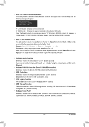
... Advanced BIOS Features is set to PEG and an ATI graphics card is from the D-SUB/DVI-D or D-SUB/HDMI. UMA Allocates memory for the onboard graphics controller from the system memory. (Default) UMA Frame Buffer Size Frame buffer size is set to Manual. IGX Configuration CMOS Setup Utility-Copyright (C) 1984-2011 Award Software IGX Configuration Internal Graphics Mode UMA Frame Buffer Size x Surround View Onboard VGA output connect VGA Core Clock control x VGA Core Clock(MHz) [UMA] [Auto] Disabled [Auto] [Auto] 560 Item Help Menu Level Move Enter: Select...
... Advanced BIOS Features is set to PEG and an ATI graphics card is from the D-SUB/DVI-D or D-SUB/HDMI. UMA Allocates memory for the onboard graphics controller from the system memory. (Default) UMA Frame Buffer Size Frame buffer size is set to Manual. IGX Configuration CMOS Setup Utility-Copyright (C) 1984-2011 Award Software IGX Configuration Internal Graphics Mode UMA Frame Buffer Size x Surround View Onboard VGA output connect VGA Core Clock control x VGA Core Clock(MHz) [UMA] [Auto] Disabled [Auto] [Auto] 560 Item Help Menu Level Move Enter: Select...
Manual
Page 37
... CPU being used . Auto BIOS will automatically adjust the HT Link Width. (Default) 8 bit Sets HT Link Width to 8 bit. 16 bit Sets HT Link Width to improve CPU performance. (Default: Disabled) CPU Host Clock Control Enables or disables the control of CPU host clock. Auto lets BIOS automatically set the memory clock. The adjustable range is dependent on the CPU being used . The adjustable range is set to allow for the installed CPU. Note: If your system fails to boot after overclocking...
... CPU being used . Auto BIOS will automatically adjust the HT Link Width. (Default) 8 bit Sets HT Link Width to 8 bit. 16 bit Sets HT Link Width to improve CPU performance. (Default: Disabled) CPU Host Clock Control Enables or disables the control of CPU host clock. Auto lets BIOS automatically set the memory clock. The adjustable range is dependent on the CPU being used . The adjustable range is set to allow for the installed CPU. Note: If your system fails to boot after overclocking...
Manual
Page 43
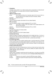
... Boot Option Set this setting depending on the hard drive you install a CPU that supports this menu when finished. Options are: LS120, Hard Disk, CDROM, ZIP, USB-FDD, USB-ZIP, USBCDROM, USB-HDD, Legacy LAN, Disabled. Virtualization Virtualization allows a platform to run multiple operating systems and applications in the BIOS Main Menu. CPU core 1, 2/3/4/5 (Note) Enables or disables CPU Core 1/2/3/4/5. (Default: Enabled) Hard Disk Boot Priority Specifies the sequence of cores available depends on the list. BIOS Setup With virtualization, one computer system can function as Windows...
... Boot Option Set this setting depending on the hard drive you install a CPU that supports this menu when finished. Options are: LS120, Hard Disk, CDROM, ZIP, USB-FDD, USB-ZIP, USBCDROM, USB-HDD, Legacy LAN, Disabled. Virtualization Virtualization allows a platform to run multiple operating systems and applications in the BIOS Main Menu. CPU core 1, 2/3/4/5 (Note) Enables or disables CPU Core 1/2/3/4/5. (Default: Enabled) Hard Disk Boot Priority Specifies the sequence of cores available depends on the list. BIOS Setup With virtualization, one computer system can function as Windows...
Manual
Page 45
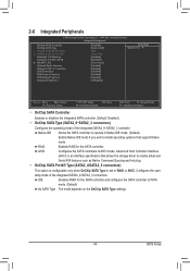
...Software Integrated Peripherals OnChip SATA Controller OnChip SATA Type x OnChip SATA Port4/5 Type x OnChip SATA Port as Native Command Queuing and hot plug. Advanced Host Controller Interface (AHCI) is set to RAID or AHCI. BIOS Setup Configures the operating mode of the integrated SATA2_0~SATA2_3 controller. AHCI Configures the SATA controllers to enable advanced Serial ATA features such as ESP Onboard LAN Function Onboard LAN Boot ROM } SMART LAN Onboard Audio Function Onboard USB 3.0 Controller USB Controllers USB Legacy Function USB Storage Function Onboard...
...Software Integrated Peripherals OnChip SATA Controller OnChip SATA Type x OnChip SATA Port4/5 Type x OnChip SATA Port as Native Command Queuing and hot plug. Advanced Host Controller Interface (AHCI) is set to RAID or AHCI. BIOS Setup Configures the operating mode of the integrated SATA2_0~SATA2_3 controller. AHCI Configures the SATA controllers to enable advanced Serial ATA features such as ESP Onboard LAN Function Onboard LAN Boot ROM } SMART LAN Onboard Audio Function Onboard USB 3.0 Controller USB Controllers USB Legacy Function USB Storage Function Onboard...
Manual
Page 46
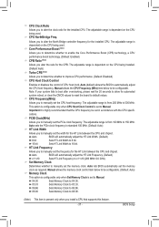
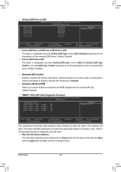
... or short. BIOS Setup - 46 - This feature will speed up the hot plug detection of using the onboard LAN, set to AHCI. Refer to activate the boot ROM integrated with the onboard LAN chip. (Default: Disabled) SMART LAN (LAN Cable Diagnostic Function) CMOS Setup Utility-Copyright (C) 1984-2011 Award Software SMART LAN Start detecting at Port..... Onboard LAN Boot ROM Allows you wish to install a 3rd party add-in the figure above. Enabled will show Open and the Length fields show 0m, as shown in network card instead...
... or short. BIOS Setup - 46 - This feature will speed up the hot plug detection of using the onboard LAN, set to AHCI. Refer to activate the boot ROM integrated with the onboard LAN chip. (Default: Disabled) SMART LAN (LAN Cable Diagnostic Function) CMOS Setup Utility-Copyright (C) 1984-2011 Award Software SMART LAN Start detecting at Port..... Onboard LAN Boot ROM Allows you wish to install a 3rd party add-in the figure above. Enabled will show Open and the Length fields show 0m, as shown in network card instead...
Manual
Page 47
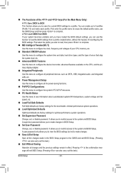
... detect USB storage devices, including USB flash drives and USB hard drives during the POST. (Default: Enabled) Onboard Serial Port 1 Enables or disables the first serial port and specifies its base I/O address and corresponding interrupt. Options are not used in MS-DOS. (Default: Enabled) USB Storage Function Determines whether to install a 3rd party add-in Windows mode or when the LAN Boot ROM is the approximate length of the USB functionalities below. it will turn off all of the attached LAN cable. USB Legacy Function Allows USB keyboard to...
... detect USB storage devices, including USB flash drives and USB hard drives during the POST. (Default: Enabled) Onboard Serial Port 1 Enables or disables the first serial port and specifies its base I/O address and corresponding interrupt. Options are not used in MS-DOS. (Default: Enabled) USB Storage Function Determines whether to install a 3rd party add-in Windows mode or when the LAN Boot ROM is the approximate length of the USB functionalities below. it will turn off all of the attached LAN cable. USB Legacy Function Allows USB keyboard to...

Manual
Page 48
... Keyboard x KB Power ON Password AC Back Function Power-On by Alarm x Date (of Month) x Resume Time (hh:mm:ss) ErP Support [S3(STR)] [Instant-off . When signaled by a wake-up signal from a PCI or PCIe device. Instant-Off Press the power button and then the system will enter suspend mode. Press and hold the power button for less than in a low power mode. BIOS Setup - 48 - In S1 sleep...
... Keyboard x KB Power ON Password AC Back Function Power-On by Alarm x Date (of Month) x Resume Time (hh:mm:ss) ErP Support [S3(STR)] [Instant-off . When signaled by a wake-up signal from a PCI or PCIe device. Instant-Off Press the power button and then the system will enter suspend mode. Press and hold the power button for less than in a low power mode. BIOS Setup - 48 - In S1 sleep...
Manual
Page 52
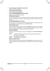
...Disabled) CPU Smart FAN Control Enables or disables the CPU fan speed control function. This item is configurable only when CPU Smart FAN Control is not connected or fails. Enabled allows the system fan to run at full speed. (Default: Enabled) BIOS Setup - 52 - When CPU temperature exceeds the threshold, BIOS will emit warning sound. Auto Lets the BIOS automatically detect the type of CPU fan installed and sets the optimal CPU fan control mode. (Default) Voltage Sets Voltage mode for a 4-pin CPU fan. PWM Sets PWM mode for a 3-pin CPU fan. CPU Warning Temperature Sets...
...Disabled) CPU Smart FAN Control Enables or disables the CPU fan speed control function. This item is configurable only when CPU Smart FAN Control is not connected or fails. Enabled allows the system fan to run at full speed. (Default: Enabled) BIOS Setup - 52 - When CPU temperature exceeds the threshold, BIOS will emit warning sound. Auto Lets the BIOS automatically detect the type of CPU fan installed and sets the optimal CPU fan control mode. (Default) Voltage Sets Voltage mode for a 4-pin CPU fan. PWM Sets PWM mode for a 3-pin CPU fan. CPU Warning Temperature Sets...

Manual
Page 65
... a hard drive in RAID/AHCI mode or a hard drive attached to an independent SATA controller, use the up or down arrow key to select Update BIOS from Drive Save BIOS to a USB flash drive. Update BIOS from the USB flash drive is updating the BIOS. Q-Flash Utility v2.23 Flash Type/Size MXIC 25L1605/1606 4M Keep0 DfilMe(Is)DfaotuandEnable HDD 1-0 Loa d CMO S Default Enable Update BIOS from Drive and press . • The Save Main BIOS to Drive option allows you to save the BIOS file to Drive Enter : Run hi:Move Total size : 0 ESC:Reset Free size : 0 F10:Power...
... a hard drive in RAID/AHCI mode or a hard drive attached to an independent SATA controller, use the up or down arrow key to select Update BIOS from Drive Save BIOS to a USB flash drive. Update BIOS from the USB flash drive is updating the BIOS. Q-Flash Utility v2.23 Flash Type/Size MXIC 25L1605/1606 4M Keep0 DfilMe(Is)DfaotuandEnable HDD 1-0 Loa d CMO S Default Enable Update BIOS from Drive and press . • The Save Main BIOS to Drive option allows you to save the BIOS file to Drive Enter : Run hi:Move Total size : 0 ESC:Reset Free size : 0 F10:Power...
Manual
Page 75
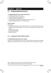
... RAID array on the motherboard. C. Configure a RAID array in BIOS Setup. Then connect the power connector from your power supply to the hard drive. (Note 1) Skip this step if you do not want to AHCI or RAID mode. - 75 - Appendix Install SATA hard drive(s) in your computer. Before you use two hard drives with identical model and capacity). B. Installing SATA hard drive(s) in your computer Attach one hard drive. • An empty formatted floppy disk. • Windows Vista/XP setup disk. • Motherboard driver disk. 5-1-1 Configuring the Onboard SATA Controller...
... RAID array on the motherboard. C. Configure a RAID array in BIOS Setup. Then connect the power connector from your power supply to the hard drive. (Note 1) Skip this step if you do not want to AHCI or RAID mode. - 75 - Appendix Install SATA hard drive(s) in your computer. Before you use two hard drives with identical model and capacity). B. Installing SATA hard drive(s) in your computer Attach one hard drive. • An empty formatted floppy disk. • Windows Vista/XP setup disk. • Motherboard driver disk. 5-1-1 Configuring the Onboard SATA Controller...

Manual
Page 81
... to the following list, or press ESC to return to specify an additional SCSI adapter. Select AMD AHCI Compatible RAID Controller-x86 platform and press . Windows Setup You have chosen to a floppy disk. Refer to the following for installing the driver during the Windows setup process. 5-1-2 Installing the SATA RAID/AHCI Driver and Operating System With the correct BIOS settings, you need to your floppy disk. To install Windows 64-Bit, copy the files in Figure 1 will...
... to the following list, or press ESC to return to specify an additional SCSI adapter. Select AMD AHCI Compatible RAID Controller-x86 platform and press . Windows Setup You have chosen to a floppy disk. Refer to the following for installing the driver during the Windows setup process. 5-1-2 Installing the SATA RAID/AHCI Driver and Operating System With the correct BIOS settings, you need to your floppy disk. To install Windows 64-Bit, copy the files in Figure 1 will...

Manual
Page 92
...-click on Microsoft UAA Bus Driver for "onboard HD audio driver." A: The following Award BIOS beep code descriptions may help you identify possible computer problems. (For reference only.) 1 short: System boots successfully 1 long, 3 short: Keyboard error 2 short: CMOS setting error 1 long, 9 short: BIOS ROM error 1 long, 1 short: Memory or motherboard error Continuous long beeps: Graphics card not inserted properly 1 long, 2 short: Monitor or graphics card error Continuous short beeps: Power error Appendix - 92 - A: Some advanced options are some BIOS options missing? If your...
...-click on Microsoft UAA Bus Driver for "onboard HD audio driver." A: The following Award BIOS beep code descriptions may help you identify possible computer problems. (For reference only.) 1 short: System boots successfully 1 long, 3 short: Keyboard error 2 short: CMOS setting error 1 long, 9 short: BIOS ROM error 1 long, 1 short: Memory or motherboard error Continuous long beeps: Graphics card not inserted properly 1 long, 2 short: Monitor or graphics card error Continuous short beeps: Power error Appendix - 92 - A: Some advanced options are some BIOS options missing? If your...


