Manual
Page 3
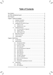
... 16 1-4-2 Installing a Memory 17 1-4-3 DIMM Population Table 17 1-5 Back Panel Connectors 18 1-6 Internal Connectors 20 1-7 Jumper Settings 33 Chapter 2 BIOS Setup 39 2-1 The Main Menu 41 2-2 Advanced Menu 43 2-2-1 PCI Subsystem Settings 44 2-2-1-1 PCI Express Settings 46 2-2-2 Runtime Error Logging 48 2-2-3 CPU Configuration 49 2-2-3-1 CPU Power Management Configuration 52 2-2-4 Fan Configuration...54 2-2-5 USB Configuration 55 2-2-6 SATA Configuration 56 2-2-7 SAS Configuration 58 2-2-8 Info Report Configuration 59 2-2-9 Super IO Configuration 60 2-2-10 Serial Port Console...
... 16 1-4-2 Installing a Memory 17 1-4-3 DIMM Population Table 17 1-5 Back Panel Connectors 18 1-6 Internal Connectors 20 1-7 Jumper Settings 33 Chapter 2 BIOS Setup 39 2-1 The Main Menu 41 2-2 Advanced Menu 43 2-2-1 PCI Subsystem Settings 44 2-2-1-1 PCI Express Settings 46 2-2-2 Runtime Error Logging 48 2-2-3 CPU Configuration 49 2-2-3-1 CPU Power Management Configuration 52 2-2-4 Fan Configuration...54 2-2-5 USB Configuration 55 2-2-6 SATA Configuration 56 2-2-7 SAS Configuration 58 2-2-8 Info Report Configuration 59 2-2-9 Super IO Configuration 60 2-2-10 Serial Port Console...
Manual
Page 7
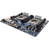
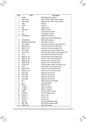
...LAN port LAN1 port (top) / USB 2.0 ports (bottom) LAN2 port (top) / USB 3.0 ports (bottom) VGA port Serial port Battery socket PMBus connector Chassis intrusion header 24 pin power connector SATA 6Gb/s connectors (SATA1 support SATA DOM function) SATA 3Gb/s connectors SAS 3Gb/s connectors 8 pin power connector (for Secondary CPU) Channel 1 slot 0 (for secondary CPU) Channel 2 slot 0 (for secondary CPU) 8 pin power connector (for Primary CPU) CPU1 fan cable connector (for Secondary CPU) Intel LGA2011 socket (Secondary CPU) Channel 4 slot 0 (for secondary CPU) Channel 3 slot 0 (for secondary CPU...
...LAN port LAN1 port (top) / USB 2.0 ports (bottom) LAN2 port (top) / USB 3.0 ports (bottom) VGA port Serial port Battery socket PMBus connector Chassis intrusion header 24 pin power connector SATA 6Gb/s connectors (SATA1 support SATA DOM function) SATA 3Gb/s connectors SAS 3Gb/s connectors 8 pin power connector (for Secondary CPU) Channel 1 slot 0 (for secondary CPU) Channel 2 slot 0 (for secondary CPU) 8 pin power connector (for Primary CPU) CPU1 fan cable connector (for Secondary CPU) Intel LGA2011 socket (Secondary CPU) Channel 4 slot 0 (for secondary CPU) Channel 3 slot 0 (for secondary CPU...

Manual
Page 10
... a motherboard, CPU or memory. Prior to installation, carefully read the user's manual and follow these procedures: • Prior to installation, do not remove or break motherboard S/N (Serial Number) sticker or warranty sticker provided by unplugging the power cord from the power outlet before installing or removing the motherboard or other hardware components. • When connecting hardware components to the internal connectors on the motherboard, make sure they are connected tightly...
... a motherboard, CPU or memory. Prior to installation, carefully read the user's manual and follow these procedures: • Prior to installation, do not remove or break motherboard S/N (Serial Number) sticker or warranty sticker provided by unplugging the power cord from the power outlet before installing or removing the motherboard or other hardware components. • When connecting hardware components to the internal connectors on the motherboard, make sure they are connected tightly...

Manual
Page 11
... Yes SATA RAID 5 Hardware Installation no upgrade ROM 1 2 5 6 9 SCU Ports 4 ports 4 ports 4 ports 8 ports 8 ports 8 ports Protocol Enabled SATA Only SATA/SAS SATA/SAS SATA/SAS SATA/SAS SATA Only - 11 - 1-2 Product Specifications CPU Chipset Memory LAN ŠŠ Support for Intel® Xeon® E5-2600 V2 series processors in the LGA2011 package ŠŠ L3 cache varies with CPU ŠŠ Supports QuickPath Interconnect up to 8GT/s ŠŠ Enhanced Intel SpeedStep Technology (EIST) ŠŠ Support Intel Virtualization Technology (VT...
... Yes SATA RAID 5 Hardware Installation no upgrade ROM 1 2 5 6 9 SCU Ports 4 ports 4 ports 4 ports 8 ports 8 ports 8 ports Protocol Enabled SATA Only SATA/SAS SATA/SAS SATA/SAS SATA/SAS SATA Only - 11 - 1-2 Product Specifications CPU Chipset Memory LAN ŠŠ Support for Intel® Xeon® E5-2600 V2 series processors in the LGA2011 package ŠŠ L3 cache varies with CPU ŠŠ Supports QuickPath Interconnect up to 8GT/s ŠŠ Enhanced Intel SpeedStep Technology (EIST) ŠŠ Support Intel Virtualization Technology (VT...

Manual
Page 12
Internal Connectors Rear Panel I/O I/O Controller Hardware Monitor BIOS Form Factor ŠŠ 1 x 24-pin ATX main power connector ŠŠ 2 x 8-pin ATX 12V power connector ŠŠ 4 x SAS connectors (SATA 3Gb/s signal) ŠŠ 2 x SATA 6Gb/s connectors ŠŠ 2 x SATA 3Gb/s connectors ŠŠ 1 x PMBus header ŠŠ 2 x CPU fan headers ŠŠ 4 x System fan headers ŠŠ 1 x Front panel header ŠŠ 1 x Back plane borad header ŠŠ 2 x USB 2.0/1.1 header ŠŠ 1 x TPM module connector ŠŠ 1 x Serial port connector ...
Internal Connectors Rear Panel I/O I/O Controller Hardware Monitor BIOS Form Factor ŠŠ 1 x 24-pin ATX main power connector ŠŠ 2 x 8-pin ATX 12V power connector ŠŠ 4 x SAS connectors (SATA 3Gb/s signal) ŠŠ 2 x SATA 6Gb/s connectors ŠŠ 2 x SATA 3Gb/s connectors ŠŠ 1 x PMBus header ŠŠ 2 x CPU fan headers ŠŠ 4 x System fan headers ŠŠ 1 x Front panel header ŠŠ 1 x Back plane borad header ŠŠ 2 x USB 2.0/1.1 header ŠŠ 1 x TPM module connector ŠŠ 1 x Serial port connector ...
Manual
Page 15
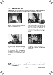
... a screw driver. Then do the same to the CPU fan header (CPU_FAN) on the motherboard. 1-3-2 Installing the CPU Cooler Refer to the steps below to correctly install the CPU cooler on the motherboard. (Actual installation process may adhere to the CPU. Inadequately removing the CPU cooler may cause interference when you tighten the screws, remove it first and replace it after tightening the screws.) Step 3: Use one...
... a screw driver. Then do the same to the CPU fan header (CPU_FAN) on the motherboard. 1-3-2 Installing the CPU Cooler Refer to the steps below to correctly install the CPU cooler on the motherboard. (Actual installation process may adhere to the CPU. Inadequately removing the CPU cooler may cause interference when you tighten the screws, remove it first and replace it after tightening the screws.) Step 3: Use one...

Manual
Page 16
... memory, switch the direction. 1-4-1 Four Channel Memory Configuration This motherboard provides eight DDR3 memory sockets and supports Four Channel Technology. After the memory is recommended that memory of the original memory bandwidth. Hardware Installation - 16 - It is installed, the BIOS will be four times of the same capacity, brand, speed, and chips be installed in Four Channel mode. 1. The four DDR3 memory sockets are unable to install the memory: • Make sure that the motherboard supports the memory. When enabling...
... memory, switch the direction. 1-4-1 Four Channel Memory Configuration This motherboard provides eight DDR3 memory sockets and supports Four Channel Technology. After the memory is recommended that memory of the original memory bandwidth. Hardware Installation - 16 - It is installed, the BIOS will be four times of the same capacity, brand, speed, and chips be installed in Four Channel mode. 1. The four DDR3 memory sockets are unable to install the memory: • Make sure that the motherboard supports the memory. When enabling...

Manual
Page 23
... connector) 1 Pin No. The motherboard supports CPU fan speed control, which requires the use of a CPU fan with fan speed control design. Hardware Installation When connecting a fan cable, be installed inside the chassis. 1 A E K R Y AB 1 5 10 15 20 22 SYS_FAN1 SYS_FAN2 SYS_FAN3 SYS_FAN4 CPU0_FAN1 CPU1_FAN1 1 Pin No. 1 2 3 4 Definition GND +12V Sense Speed Control • Be sure to connect fan cables to the fan headers to the CPU or the system may hang. • These fan headers are not configuration jumper blocks. Do not place a jumper...
... connector) 1 Pin No. The motherboard supports CPU fan speed control, which requires the use of a CPU fan with fan speed control design. Hardware Installation When connecting a fan cable, be installed inside the chassis. 1 A E K R Y AB 1 5 10 15 20 22 SYS_FAN1 SYS_FAN2 SYS_FAN3 SYS_FAN4 CPU0_FAN1 CPU1_FAN1 1 Pin No. 1 2 3 4 Definition GND +12V Sense Speed Control • Be sure to connect fan cables to the fan headers to the CPU or the system may hang. • These fan headers are not configuration jumper blocks. Do not place a jumper...
Manual
Page 36
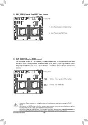
... two pins to temporarily short the two pins or use a metal object like a screwdriver to touch the two pins for BIOS configurations). Hardware Installation - 36 - A E K R Y AB 1 5 6) CLR_CMOS1 (Clearing CMOS Jumper) Use this jumper to remove the jumper cap from the power outlet before clearing the CMOS values. • After clearing the CMOS values and before turning on your computer and unplug the power cord from the jumper. date information and BIOS configurations) and reset the CMOS values...
... two pins to temporarily short the two pins or use a metal object like a screwdriver to touch the two pins for BIOS configurations). Hardware Installation - 36 - A E K R Y AB 1 5 6) CLR_CMOS1 (Clearing CMOS Jumper) Use this jumper to remove the jumper cap from the power outlet before clearing the CMOS values. • After clearing the CMOS values and before turning on your computer and unplug the power cord from the jumper. date information and BIOS configurations) and reset the CMOS values...

Manual
Page 39
... changes Main Menu: Exit the BIOS Setup program Submenus: Exit current submenu Show descriptions of general help Restore the previous BIOS settings for the current submenus Load the Optimized BIOS default settings for how to clear the CMOS values.) BIOS Setup Program Function Keys Move the selection bar to select the screen Move the selection bar to keep the configuration values in the CMOS. BIOS Setup When the power is turned on the motherboard...
... changes Main Menu: Exit the BIOS Setup program Submenus: Exit current submenu Show descriptions of general help Restore the previous BIOS settings for the current submenus Load the Optimized BIOS default settings for how to clear the CMOS values.) BIOS Setup Program Function Keys Move the selection bar to select the screen Move the selection bar to keep the configuration values in the CMOS. BIOS Setup When the power is turned on the motherboard...

Manual
Page 44
.../64 PCI Bus Clocks/96 PCI Bus Clocks/128 PCI Bus Clocks/160 PCI Bus Clocks/192 PCI Bus Clocks/224 PCI Bus Clocks/248 PCI Bus Clocks. Options available: Enabled/Disabled. Default setting is 32 PCI Bus Clocks. PCI 64bit Resources Handling Above 4G Decoding Enable/Disable Above 4G Decoding. Default setting is Enabled. 2-2-1 PCI Subsystem Settings PCI Express Slot 1/2/3/4 I/O ROM When enabled, This setting will initialize the device expansion ROM for the related PCI-E slot. Options available: Enabled/Disabled. Default setting is PXE. Onboard LAN1/2 Controller Enable/Disable Onboard LAN...
.../64 PCI Bus Clocks/96 PCI Bus Clocks/128 PCI Bus Clocks/160 PCI Bus Clocks/192 PCI Bus Clocks/224 PCI Bus Clocks/248 PCI Bus Clocks. Options available: Enabled/Disabled. Default setting is 32 PCI Bus Clocks. PCI 64bit Resources Handling Above 4G Decoding Enable/Disable Above 4G Decoding. Default setting is Enabled. 2-2-1 PCI Subsystem Settings PCI Express Slot 1/2/3/4 I/O ROM When enabled, This setting will initialize the device expansion ROM for the related PCI-E slot. Options available: Enabled/Disabled. Default setting is PXE. Onboard LAN1/2 Controller Enable/Disable Onboard LAN...

Manual
Page 46
... Set maximum playlooad for PCI Express Device or allow device to use 8-bit Tag field as a requester. Default setting is Enabled. Options available: Enabled/Disabled. Default setting is Enabled. Default setting is Disabled. BIOS Setup - 46 - Options available: Enabled/Disabled. Options available: Enabled/Disabled. Options available: Enabled/Disabled. Options available: Auto/128 Bytes/256 Bytes/512 Bytes/1024 Bytes/2048 Bytes/4096 Bytes. Extended Tag Wnen this feature is enabled, the system will allow system BIOS to select the value. Default setting is Auto...
... Set maximum playlooad for PCI Express Device or allow device to use 8-bit Tag field as a requester. Default setting is Enabled. Options available: Enabled/Disabled. Default setting is Enabled. Default setting is Disabled. BIOS Setup - 46 - Options available: Enabled/Disabled. Options available: Enabled/Disabled. Options available: Enabled/Disabled. Options available: Auto/128 Bytes/256 Bytes/512 Bytes/1024 Bytes/2048 Bytes/4096 Bytes. Extended Tag Wnen this feature is enabled, the system will allow system BIOS to select the value. Default setting is Auto...
Manual
Page 50
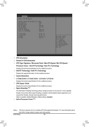
.... BIOS Setup - 50 - CPU Information Socket 0/1 CPU Information CPU Type/ Signature / Microcode Patch / Max CPU Speed / Min CPU Speed / Processor Cores / Intel HT Technology / Intel VT-x Technology Displays the technical specifications for the installed processor. Default setting is present only if you install a CPU that supports this feature. CPU Speed / 64-bit Displays the technical specifications for the installed processor. For more separate threads concurrently. Active Processor Cores (Note) (Note) This item is Enabled. When hyper-threading is enabled, multi-threaded software...
.... BIOS Setup - 50 - CPU Information Socket 0/1 CPU Information CPU Type/ Signature / Microcode Patch / Max CPU Speed / Min CPU Speed / Processor Cores / Intel HT Technology / Intel VT-x Technology Displays the technical specifications for the installed processor. Default setting is present only if you install a CPU that supports this feature. CPU Speed / 64-bit Displays the technical specifications for the installed processor. For more separate threads concurrently. Active Processor Cores (Note) (Note) This item is Enabled. When hyper-threading is enabled, multi-threaded software...
Manual
Page 55
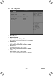
Default setting is Enabled. Options available: Enabled/Disabled. EHCI Hand-off Enable/Disable EHCI (USB 2.0) Hand-off function. USB3.0 Support Enables or disables onboard USB 3.0 devices. Options available: Enabled/Disabled. Default setting is Enabled. BIOS Setup Options available: Auto/Enabled/Disabled. 2-2-5 USB Configuration USB Configuration Legacy USB Support Enables or disables support for legacy USB devices. Options available: Enabled/Disabled. Default setting is Enabled. Default setting is Disabled. - 55 - XHCI Hand-off Enable/Disable EHCI (USB 3.0) Hand-off...
Default setting is Enabled. Options available: Enabled/Disabled. EHCI Hand-off Enable/Disable EHCI (USB 2.0) Hand-off function. USB3.0 Support Enables or disables onboard USB 3.0 devices. Options available: Enabled/Disabled. Default setting is Enabled. BIOS Setup Options available: Auto/Enabled/Disabled. 2-2-5 USB Configuration USB Configuration Legacy USB Support Enables or disables support for legacy USB devices. Options available: Enabled/Disabled. Default setting is Enabled. Default setting is Disabled. - 55 - XHCI Hand-off Enable/Disable EHCI (USB 3.0) Hand-off...
Manual
Page 57
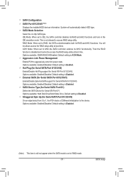
...Port 0/1. Default setting is Disabled. This is set to access RAID setup utility. You will be access the RAID setup utility at boot time. Default setting is Enabled. BIOS Setup SATA Mode Selection Select the on chip SATA type. IDE Mode: When set ot RAID mode. - 57 - ACHI Mode: When set to the device. Default setting is ACHI Mode. SATA Device Type (for Serial SATA Port 0/1) Define the SATA Device for Serial ATA Port 0/1/2/3/4/5. Aggressive Link Power Management Enable PCH to AHCI,the SATA controller enables its AHCI functionality. Options available: Hard Disk...
...Port 0/1. Default setting is Disabled. This is set to access RAID setup utility. You will be access the RAID setup utility at boot time. Default setting is Enabled. BIOS Setup SATA Mode Selection Select the on chip SATA type. IDE Mode: When set ot RAID mode. - 57 - ACHI Mode: When set to the device. Default setting is ACHI Mode. SATA Device Type (for Serial SATA Port 0/1) Define the SATA Device for Serial ATA Port 0/1/2/3/4/5. Aggressive Link Power Management Enable PCH to AHCI,the SATA controller enables its AHCI functionality. Options available: Hard Disk...
Manual
Page 64
... Switch to capture Terminal data. When disabled, COM1 Switch to enable console redirection after O.S has loaded. Default setting is Disabled. (Note) The item is even. The standard setting is Always Enable. Options available: Enabled/Disabled. Resolution 100x31 (Note) Enables or disables extended terminal resolution. Options available: 80x24/80X25. Redirection After BIOS POST (Note) This option allows user to IT8728 SOL UART. BIOS Setup - 64 - Odd: parity bit is0if num of a Windows Server OS through a serial port. Default setting...
... Switch to capture Terminal data. When disabled, COM1 Switch to enable console redirection after O.S has loaded. Default setting is Disabled. (Note) The item is even. The standard setting is Always Enable. Options available: Enabled/Disabled. Resolution 100x31 (Note) Enables or disables extended terminal resolution. Options available: 80x24/80X25. Redirection After BIOS POST (Note) This option allows user to IT8728 SOL UART. BIOS Setup - 64 - Odd: parity bit is0if num of a Windows Server OS through a serial port. Default setting...
Manual
Page 70
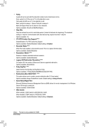
...: Enabled/Disabled. Options available: Enabled/Disabled. BIOS Setup - 70 - Options available: Enabled/Disabled. Current Memory Mode Displays the current memory mode. Memory Mode Determine the memory mode. Options available: Indpendent /Mirroring/ Lockstep/Sparing. The Rank Interleaving works between different physical banks. Options available: Auto/Force DDR3 800/Force DDR3 1066/Force DDR3 1333/Force DDR3 1600/Force DDR3 1866. Default setting is Disabled. Default setting is Enabled. Mirroring/Sparing Displays the current support memory mode. DDR Speed Configure...
...: Enabled/Disabled. Options available: Enabled/Disabled. BIOS Setup - 70 - Options available: Enabled/Disabled. Current Memory Mode Displays the current memory mode. Memory Mode Determine the memory mode. Options available: Indpendent /Mirroring/ Lockstep/Sparing. The Rank Interleaving works between different physical banks. Options available: Auto/Force DDR3 800/Force DDR3 1066/Force DDR3 1333/Force DDR3 1600/Force DDR3 1866. Default setting is Disabled. Default setting is Enabled. Mirroring/Sparing Displays the current support memory mode. DDR Speed Configure...
Manual
Page 73
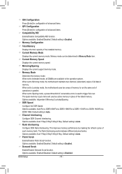
... Technology) Enable/Disable Intel I /O Configuration Press [Enter] for Gen3 Equalization Workaround. VGA Priority Define the display device priority. Default setting is Disabled. Default setting is 64G. Options available: Auto/Manual. Default setting is Disabled. Default setting is Enabled. - 73 - Default setting is 0x80000000. Options available: Enabled/Disabled. Options available: Enabled/Disabled. DCA Support (Direct Cache Access) Enable/Disable Intel DCA Support function. No Snoop Optimization Options VC0/VCP/VC1. BIOS Setup TargetVGA Display the Target VGA support...
... Technology) Enable/Disable Intel I /O Configuration Press [Enter] for Gen3 Equalization Workaround. VGA Priority Define the display device priority. Default setting is Disabled. Default setting is 64G. Options available: Auto/Manual. Default setting is Disabled. Default setting is Enabled. - 73 - Default setting is 0x80000000. Options available: Enabled/Disabled. Options available: Enabled/Disabled. DCA Support (Direct Cache Access) Enable/Disable Intel DCA Support function. No Snoop Optimization Options VC0/VCP/VC1. BIOS Setup TargetVGA Display the Target VGA support...

Manual
Page 74
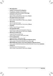
...Speed Mode Configure QPI Link Speed mode. QPI Link Frequency Select Configure QPI Link Frequency. QPI Link0p Options available: Enabled/Disabled. Default setting is Auto. Default setting is Enabled. Default setting is Disabled. Default setting is Disabled. Default setting is Disabled. QPI Link0s Options available: Enabled/Disabled. BIOS Setup - 74 - 2-3-1-2 QPI Configuration Current QPI Link Speed/ Current QPI Link Freq Displays the current QPI Link Speed and Frequency information. Options available: Fast/Slow. QPI Link1 Options available: Enabled/Disabled...
...Speed Mode Configure QPI Link Speed mode. QPI Link Frequency Select Configure QPI Link Frequency. QPI Link0p Options available: Enabled/Disabled. Default setting is Auto. Default setting is Enabled. Default setting is Disabled. Default setting is Disabled. Default setting is Disabled. QPI Link0s Options available: Enabled/Disabled. BIOS Setup - 74 - 2-3-1-2 QPI Configuration Current QPI Link Speed/ Current QPI Link Freq Displays the current QPI Link Speed and Frequency information. Options available: Fast/Slow. QPI Link1 Options available: Enabled/Disabled...

Manual
Page 79
... unauthorized use by setting up access passwords. Administrator Password Press Enter to configure the user password. - 79 - User Password Press Enter to configure the Administrator password. 2-4 Security Menu The Security menu allows you can only access and modify the System Time, System Date, and Set User Password fields. There are two types of passwords that you to the Setup menus. BIOS Setup A user can set: • Administrator Password Entering this password will allow the user to access and change all settings in the Setup Utility. • User Password Entering...
... unauthorized use by setting up access passwords. Administrator Password Press Enter to configure the user password. - 79 - User Password Press Enter to configure the Administrator password. 2-4 Security Menu The Security menu allows you can only access and modify the System Time, System Date, and Set User Password fields. There are two types of passwords that you to the Setup menus. BIOS Setup A user can set: • Administrator Password Entering this password will allow the user to access and change all settings in the Setup Utility. • User Password Entering...


