Gigabyte GA-7PESLN Support and Manuals
Get Help and Manuals for this Gigabyte item
View All Support Options Below
Free Gigabyte GA-7PESLN manuals!
Problems with Gigabyte GA-7PESLN?
Ask a Question
Free Gigabyte GA-7PESLN manuals!
Problems with Gigabyte GA-7PESLN?
Ask a Question
Popular Gigabyte GA-7PESLN Manual Pages
Manual - Page 1
GA-7PESL GA-7PESLX GA-7PESLN
Dual LGA1356 sockets motherboard for Intel® Xeon series processors
User's Manual
Rev. 1001
Manual - Page 3
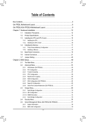
... Three Channel Memory Configuration 17 1-4-2 Installing a Memory 18 1-5 Back Panel Connectors 19 1-6 Internal Connectors 21 1-7 Jumper Setting 40
Chapter 2 BIOS Setup 49 2-1 The Main Menu 51 2-2 Advanced Menu 53
2-2-1 H/W Monitor (GA-7PESLN 55 2-2-2 PCI Configuration...56 2-2-3 Trusted Computing 57 2-2-4 CPU Configuration 58 2-2-5 Runtime Error Logging 62 2-2-6 SATA Configuration 63...
Manual - Page 10
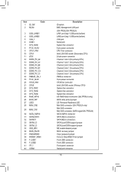
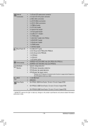
Item 1 ID_SW 2 MLAN
Code
3 USB_LANB1 4 USB_LANB2 5 VGA_1 6 COM1 7 SYS_FAN3 8 P12V_AUX2 9 ...Firmware Readiness LED Mini SAS connector (GA-7PESLX only) Mini SAS connector Mini SAS connector (SATA signal/GA-7PESLN) SATA SGPIO connector SATA 3Gb/s connectors SATA 6Gb/s connectors SATA3 port DOM support jumper SATA2 port DOM support jumper ME enable/disable jumper BIOS recovery jumper Clear password...
Manual - Page 13

... 5
SATA RAID 5
No Yes No Yes SATA RAID 5
Hardware Installation no upgrade ROM
1 2 5 6 9
SCU Ports
4 ports
4 ports 4 ports 8 ports 8 ports 8 ports
Protocol Enabled
SATA Only
SATA/SAS SATA/SAS SATA/SAS SATA/SAS SATA Only
- 13 -
1-2 Product Specifications
CPU
Chipset Memory
LAN
ŠŠ Support for Dual Intel® Xeon® Sandy-bridge-EN...
Manual - Page 14
... Form Factor; 12 inch x 13 inch, 6 layers PCB
ŠŠ GA-7PESLX: EEB Form Factor; 12 inch x 13 inch, 8 layers PCB
ŠŠ GA-7PESLN: EEB Form Factor; 12 inch x 13 inch, 8 layers PCB
* GIGABYTE reserves the right to make any changes to the product specifications and product-related information without prior notice.
- 14 - Hardware Installation
Manual - Page 22

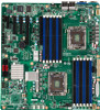
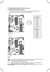
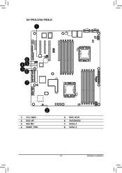
Hardware Installation GA-7PESLX/GA-7PESLN
21 18 24 17
16 20 15 14
10
3 6
12
11
1
19
4
13
23 22 9 8
1) 2) 3) 4) 5) 6) 7) 8) 9) 10) 11) 12) 13)
ATX1 P12V_AUX1 P12V_AUX2 PMBUS_CN_1 CPU0_FAN (for primary CPU) CPU1_FAN (for seconary CPU) SYS_FAN1 (System Fan) SYS_FAN2 (System Fan) SYS_FAN4 (System Fan) SYS_FAN3 (System Fan) SATA2/3/4/5 SATA0/1 MIN_CN1/ MINII_CN2 (GA-7PESLX only...
Manual - Page 27
...Installation
- 27 -
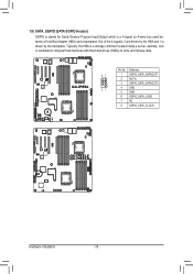
SATA0 SATA1
When SATA_DOM1/2 jumper are set to Normal Mode:
GA-7PESL
SATA0 SATA1
7
7
1
1
Pin No. 1 2 3 4 5 6 7
Definition GND TXP TXN GND RXN RXP GND
SATA5
SATA4
SATA3 SATA2
SATA0 SATA1
When SATA_DOM1/2 Jumper are set to SATA 6Gb/s standard and are connected. Definition
1 GND 2 TXP 3 TXN 4 GND 5 RXN 6 RXP 7 P5V
GA-7PESLX GA-7PESLN... connector supports a ...
Manual - Page 33
...
Pin No. Definition
87
1 SGPIO_SATA_DATAOUT1
2 No Pin
3 SGPIO_SATA_DATAOUT0
21
4 GND
5 GND
6 SGPIO_SATA_LOAD
7 NC
8 SGPIO_SATA_CLOCK
GA-7PESLX GA-7PESLN
Hardware Installation
- 33 - 19) SATA_SGPIO (SATA SGPIO Header)
SGPIO is stands for Serial General Purpose Input/Output which is driven by the HBA and 1 is a 4-signal (or 4-...
Manual - Page 34
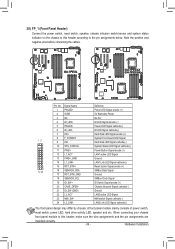
... the wire assignments and the pin assignments are
matched correctly. - 34 - Hardware Installation
Hard Disk LED Signal cathode(-)
10 SYS_STATUS-
Chassis intrusion Signal cathode(-)
21 ID_SW (GND)
Ground
22 L2_ACT
LAN2 active LED Signal
23 NMI_SW-
GA-7PESL
GA-7PESLX GA-7PESLN
Pin No. System Status LED Signal cathode(-)
11 PWB+
Power Button Signal anode...
Manual - Page 35
... or may clear the CMOS values by yourself or uncertain about the battery
model.
• When installing the battery, note the orientation of the positive side (+) and the negative...• Used batteries must be lost. Hardware Installation
GA-7PESL
You may be handled in accordance with local environmental regulations.
- 35 - Replace the battery when the battery voltage drops to...
Manual - Page 38
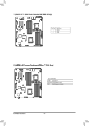
22) RAID_KEY2 (RAID Select Hearder/GA-7PESLX Only)
GA-7PESLX GA-7PESLN
Pin No. 1 2
Definition GPIO GND
23) LED2 (LSI Firmware Readiness LED/GA-7PESLX Only)
GA-7PESLX GA-7PESLN
LED2 Link/Activity:
State Description Blinking LSI firmware is ready
Off
LSI firmware is not ready
Hardware Installation
- 38 -
Manual - Page 39
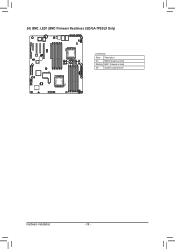
24) BMC_LED1 (BMC Firmware Readiness LED/GA-7PESLX Only)
GA-7PESLX GA-7PESLN
Link/Activity:
State Description
On
BMC firmware is initial
Blinking BMC firmware is ready
Off
System is powered off
Hardware Installation
- 39 -
Manual - Page 41
Hardware Installation
GA-7PESLX/GA-7PESLN
1
6 45 38
7
2
1) CLR_CMOS 2) BIOS_WP 3) SSB_ME1 4) ROMST_FRB3
5) BIOS_RCVR 6) PASSSWORD 7) SATA2_D 8) SATA3_D
- 41 -
Manual - Page 42
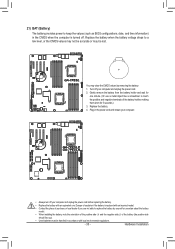
...BIOS configurations). Hardware Installation
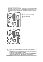
- 42 - date information and BIOS configurations) and reset the CMOS values to remove the jumper cap from the jumper. 1) CLR_CMOS (Clearing CMOS Jumper)
Use this jumper to Chapter 2, "BIOS Setup," for a few seconds.
1
1-2 Close: Normal operation (Default setting)
2-3 Close: Clear CMOS data. 1
GA-7PESL
GA-7PESLX GA-7PESLN
• Always turn...
Manual - Page 43
GA-7PESLX GA-7PESLN
Hardware Installation
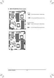
- 43 - GA-7PESLX/GA-7PESLN 1 1-2 Close: Normal operation. (Default setting)
1 2-3 Close: Enable BIOS write protect function. 2) BIOS_WP (BIOS Write Protect Jumper)
GA-7PESL
1
1-2 Close: Normal operation. (Default setting)
GA-7PESL
1
2-3 Close: Enable BIOS write protect function.
Gigabyte GA-7PESLN Reviews
We have not received any reviews for Gigabyte yet.