
User Manual
Page 4
Table of Contents GA-7N400S/GA-7N400S-L Motherboard Layout 6 Block Diagram ...7 Chapter 1 Hardware Installation 9 1-1 Considerations Prior to Installation 9 1-2 Feature Summary 10 1-3 Set System Clock (CLK_SW 11 1-4 ... Memory 13 1-6 Installation of Expansion Cards 15 1-7 I/O Back Panel Introduction 16 1-8 Connectors Introduction 17 Chapter 2 BIOS Setup 27 The Main Menu (For example: BIOS Ver. : E17 28 2-1 Standard CMOS Features 30 2-2 Advanced BIOS Features 32 2-3 Advanced Chipset Features 34 2-4 Integrated Peripherals 35 2-5 Power Management Setup 39 2-6 PnP/PCI Configurations...
Table of Contents GA-7N400S/GA-7N400S-L Motherboard Layout 6 Block Diagram ...7 Chapter 1 Hardware Installation 9 1-1 Considerations Prior to Installation 9 1-2 Feature Summary 10 1-3 Set System Clock (CLK_SW 11 1-4 ... Memory 13 1-6 Installation of Expansion Cards 15 1-7 I/O Back Panel Introduction 16 1-8 Connectors Introduction 17 Chapter 2 BIOS Setup 27 The Main Menu (For example: BIOS Ver. : E17 28 2-1 Standard CMOS Features 30 2-2 Advanced BIOS Features 32 2-3 Advanced Chipset Features 34 2-4 Integrated Peripherals 35 2-5 Power Management Setup 39 2-6 PnP/PCI Configurations...

User Manual
Page 5
Chapter 3 Drivers Installation 47 3-1 Install Chipset Drivers 47 3-2 Software Application 48 3-3 Software Information 48 3-4 Hardware Information 49 3-5 Contact Us ...49 Chapter 4 Appendix 51 4-1 Unique Software Utilities 51 4-1-1 Xpress Recovery Introduction 51 4-1-2 Flash BIOS Method Introduction 54 4-1-3 Serial ATA BIOS Setting Utility Introduction 63 4-1-4 2- / 4- / 6- Channel Audio Function Introduction 69 4-2 Troubleshooting 77 - 5 -
Chapter 3 Drivers Installation 47 3-1 Install Chipset Drivers 47 3-2 Software Application 48 3-3 Software Information 48 3-4 Hardware Information 49 3-5 Contact Us ...49 Chapter 4 Appendix 51 4-1 Unique Software Utilities 51 4-1-1 Xpress Recovery Introduction 51 4-1-2 Flash BIOS Method Introduction 54 4-1-3 Serial ATA BIOS Setting Utility Introduction 63 4-1-4 2- / 4- / 6- Channel Audio Function Introduction 69 4-2 Troubleshooting 77 - 5 -

User Manual
Page 6
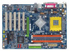
GA-7N400S DDR1 DDR2 DDR3 GA-7N400S/GA-7N400S-L Motherboard Layout KB_MS ATX_12V SOCKET A R_USB ATX COMA LPT COMB USB MIC_IN LINE_OUT LINE_IN LAN* SUR_CEN RTL8100C* SPDIF_IO CODEC F_AUDIO CD_IN AUX_IN nVIDIA nForce 2 Ultra 400 CLK_SW CPU_FAN AGP PCI1 PCI2 PCI3 IDE2 IDE1 nVIDIA nForce 2 MCP RAID SATA1 SATA0 PCI4 BIOS BAT CLR_CMOS PCI5 FDD PWR_LED IR F_USB1 F_USB2 F_PANEL SYS_FAN -L* IT8712 * Only for GA-7N400S-L. - 6 -
GA-7N400S DDR1 DDR2 DDR3 GA-7N400S/GA-7N400S-L Motherboard Layout KB_MS ATX_12V SOCKET A R_USB ATX COMA LPT COMB USB MIC_IN LINE_OUT LINE_IN LAN* SUR_CEN RTL8100C* SPDIF_IO CODEC F_AUDIO CD_IN AUX_IN nVIDIA nForce 2 Ultra 400 CLK_SW CPU_FAN AGP PCI1 PCI2 PCI3 IDE2 IDE1 nVIDIA nForce 2 MCP RAID SATA1 SATA0 PCI4 BIOS BAT CLR_CMOS PCI5 FDD PWR_LED IR F_USB1 F_USB2 F_PANEL SYS_FAN -L* IT8712 * Only for GA-7N400S-L. - 6 -

User Manual
Page 7
Block Diagram AGP 4X/8X AMD-K7 CPU CPUCLK+/-(100/133/166/200MHz) 5 PCI AGPCLK 66MHz RJ45* RTL8100C* PCI Bus 33MHz nVIDIA nForce 2 Ultra 400 nVIDIA nForce 2 MCP RAID DDR 400/333/266MHz DIMM DDR HCLK+/- (100/133/166/200MHz) NBGCLK 66 MHz 33MHz 14.318MHz 48MHz BIOS IT8712 Floppy LPT Port AC97 Link PCICLK (33MHz) CODEC 2 Serial ATA 8 USB ATA33/66/100/ Ports 133 IDE Channels 2 COM Ports 24MHz 33MHz PS/2 KB/Mouse Mic In Line In Line Out * Only for GA-7N400S-L. - 7 -
Block Diagram AGP 4X/8X AMD-K7 CPU CPUCLK+/-(100/133/166/200MHz) 5 PCI AGPCLK 66MHz RJ45* RTL8100C* PCI Bus 33MHz nVIDIA nForce 2 Ultra 400 nVIDIA nForce 2 MCP RAID DDR 400/333/266MHz DIMM DDR HCLK+/- (100/133/166/200MHz) NBGCLK 66 MHz 33MHz 14.318MHz 48MHz BIOS IT8712 Floppy LPT Port AC97 Link PCICLK (33MHz) CODEC 2 Serial ATA 8 USB ATA33/66/100/ Ports 133 IDE Channels 2 COM Ports 24MHz 33MHz PS/2 KB/Mouse Mic In Line In Line Out * Only for GA-7N400S-L. - 7 -

User Manual
Page 10
.../ 4 / 6 channel audio Š Supports Line In (Rear Speaker Out) ; Line Out (Front Speaker Out) ; GA-7N400S(-L) Motherboard - 10 - English 1-2 Feature Summary Motherboard Š GA-7N400S or GA-7N400S-L CPU Š Socket A for AMD SempronTM / AthlonTM XP / AthlonTM / DuronTM processor Š Supports 200/266/333/... serial ports (COMA, COMB) Š 8 USB 2.0/1.1 ports (rear x 4, front x 4 via BIOS (CPU/ DDR/ AGP) Form Factor Š ATX form factor; 30.5cm x 21.0cm * Only for GA-7N400S-L. (Note) If you install. You also have to install DDR333 or DDR400 memory module(s).
.../ 4 / 6 channel audio Š Supports Line In (Rear Speaker Out) ; Line Out (Front Speaker Out) ; GA-7N400S(-L) Motherboard - 10 - English 1-2 Feature Summary Motherboard Š GA-7N400S or GA-7N400S-L CPU Š Socket A for AMD SempronTM / AthlonTM XP / AthlonTM / DuronTM processor Š Supports 200/266/333/... serial ports (COMA, COMB) Š 8 USB 2.0/1.1 ports (rear x 4, front x 4 via BIOS (CPU/ DDR/ AGP) Form Factor Š ATX form factor; 30.5cm x 21.0cm * Only for GA-7N400S-L. (Note) If you install. You also have to install DDR333 or DDR400 memory module(s).

User Manual
Page 13
... DDR Fig.1 The DIMM socket has a notch, so the DIMM memory module can differ with the following conditions: 1. The motherboard supports DDR memory modules, whereby BIOS will automatically detect memory capacity and specifications. Hardware Installation Before installing or removing memory modules, please make sure that the memory used can only fit...
... DDR Fig.1 The DIMM socket has a notch, so the DIMM memory module can differ with the following conditions: 1. The motherboard supports DDR memory modules, whereby BIOS will automatically detect memory capacity and specifications. Hardware Installation Before installing or removing memory modules, please make sure that the memory used can only fit...

User Manual
Page 14
If two DDR memory modules are installed (same storage capacity), one DDR memory module is for BIOS to the limitation of Intel chipset specifications. 1. We'll strongly recommend our user to slot two DDR memory modules into the DIMMs with the same..., SS: Single Side) 2 memory module 3 memory module DDR 1 DS/SS X DS/SS DDR 2 X DS/SS DS/SS DDR 3 DS/SS DS/SS DS/SS GA-7N400S(-L) Motherboard - 14 - GA-7N400S / GA-7N400S-L includes 3 DIMM sockets as following: Channel A : DDR 1, DDR 2 Channel B : DDR 3 If you want to operate the Dual Channel Technology, please note the following ...
If two DDR memory modules are installed (same storage capacity), one DDR memory module is for BIOS to the limitation of Intel chipset specifications. 1. We'll strongly recommend our user to slot two DDR memory modules into the DIMMs with the same..., SS: Single Side) 2 memory module 3 memory module DDR 1 DS/SS X DS/SS DDR 2 X DS/SS DS/SS DDR 3 DS/SS DS/SS DS/SS GA-7N400S(-L) Motherboard - 14 - GA-7N400S / GA-7N400S-L includes 3 DIMM sockets as following: Channel A : DDR 1, DDR 2 Channel B : DDR 3 If you want to operate the Dual Channel Technology, please note the following ...

User Manual
Page 15
... align the VGA card to secure the slot bracket of the expansion card. 6. Make sure your computer's chassis cover. 7. Install related driver from BIOS. 8. Replace your VGA card is locked by following the steps outlined below: 1. Read the related expansion card's instruction document before install the expansion ...card into expansion slot in the slot. 5. Be sure the metal contacts on the computer, if necessary, setup BIOS utility of the AGP slot when you try to install/uninstall the VGA card. Installing a AGP VGA card: Please carefully pull out the...
... align the VGA card to secure the slot bracket of the expansion card. 6. Make sure your computer's chassis cover. 7. Install related driver from BIOS. 8. Replace your VGA card is locked by following the steps outlined below: 1. Read the related expansion card's instruction document before install the expansion ...card into expansion slot in the slot. 5. Be sure the metal contacts on the computer, if necessary, setup BIOS utility of the AGP slot when you try to install/uninstall the VGA card. Installing a AGP VGA card: Please carefully pull out the...

User Manual
Page 20
... on one IDE cable, and the single IDE cable can then connect to two IDE devices (hard drive or optical drive). Please refer to the BIOS setting for information on settings, please refer to the instructions located on the IDE device). 40 39 2 1 7) SATA0 / SATA1 (Serial ATA Connector) Serial ATA can... rate. English 6) IDE1 / IDE2 (IDE Connector) An IDE device connects to work properly. 1 7 SATA1 1 7 SATA0 Pin No. 1 2 3 4 5 6 7 Definition GND TXP TXN GND RXN RXP GND GA-7N400S(-L) Motherboard - 20 -
... on one IDE cable, and the single IDE cable can then connect to two IDE devices (hard drive or optical drive). Please refer to the BIOS setting for information on settings, please refer to the instructions located on the IDE device). 40 39 2 1 7) SATA0 / SATA1 (Serial ATA Connector) Serial ATA can... rate. English 6) IDE1 / IDE2 (IDE Connector) An IDE device connects to work properly. 1 7 SATA1 1 7 SATA0 Pin No. 1 2 3 4 5 6 7 Definition GND TXP TXN GND RXN RXP GND GA-7N400S(-L) Motherboard - 20 -

User Manual
Page 27
... the CMOS SETUP screen. Exit current page and return to a new BIOS, either Gigabyte's Q-Flash or @BIOS utility can enter the BIOS setup screen by pressing "Ctrl + F1". You can be reset to DOS before upgrading BIOS but directly download and update BIOS from BIOS default table Load the Optimized Defaults Q-Flash utility System Information Save all...
... the CMOS SETUP screen. Exit current page and return to a new BIOS, either Gigabyte's Q-Flash or @BIOS utility can enter the BIOS setup screen by pressing "Ctrl + F1". You can be reset to DOS before upgrading BIOS but directly download and update BIOS from BIOS default table Load the Optimized Defaults Q-Flash utility System Information Save all...

User Manual
Page 28
GA-7N400S(-L) Motherboard - 28 - CMOS Setup Utility-Copyright (C) 1984-2004 Award Software ` Standard CMOS Features ` Advanced BIOS Features ` Advanced Chipset Features ` Integrated Peripherals ` Power Management Setup ` PnP/PCI Configurations ` PC Health Status ESC: Quit F8: Q-Flash ...press to search the advanced option hidden. „ Standard CMOS Features This setup page includes all the items in standard compatible BIOS. „ Advanced BIOS Features This setup page includes all the items of Award special enhanced features. „ Advanced Chipset Features This setup page includes...
GA-7N400S(-L) Motherboard - 28 - CMOS Setup Utility-Copyright (C) 1984-2004 Award Software ` Standard CMOS Features ` Advanced BIOS Features ` Advanced Chipset Features ` Integrated Peripherals ` Power Management Setup ` PnP/PCI Configurations ` PC Health Status ESC: Quit F8: Q-Flash ...press to search the advanced option hidden. „ Standard CMOS Features This setup page includes all the items in standard compatible BIOS. „ Advanced BIOS Features This setup page includes all the items of Award special enhanced features. „ Advanced Chipset Features This setup page includes...

User Manual
Page 29
It allows you to limit access to the system. „ Save & Exit Setup Save CMOS value settings to Setup. „ Set User Password Change, set , or disable password. It allows you to limit access to the system and Setup, or just to CMOS and exit setup. „ Exit Without Saving Abandon all CMOS value changes and exit setup. - 29 - BIOS Setup English „ Load Optimized Defaults Optimized Defaults indicates the value of the system parameters which the system would be in best performance configuration. „ Set Supervisor Password Change, set , or disable password.
It allows you to limit access to the system. „ Save & Exit Setup Save CMOS value settings to Setup. „ Set User Password Change, set , or disable password. It allows you to limit access to the system and Setup, or just to CMOS and exit setup. „ Exit Without Saving Abandon all CMOS value changes and exit setup. - 29 - BIOS Setup English „ Load Optimized Defaults Optimized Defaults indicates the value of the system parameters which the system would be in best performance configuration. „ Set Supervisor Password Change, set , or disable password.
User Manual
Page 30
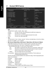
...IDE Channel 0 Master/Slave; IDE Channel 2/3 Master IDE and SATA devices setup. Week Month The week, from Sun to Sat, determined by the BIOS and is calculated base on the 24-hour military- IDE Channel 2/3 Master IDE HDD Auto-Detection Press "Enter" to set the access mode for...skip the automatic Manual detection step and allow for the hard drive. time clock. Enter the appropriate option based on the outside drive casing. GA-7N400S(-L) Motherboard - 30 - Day The day, from 1999 through 2098 Time The times format in the month) Base Memory Extended Memory Total Memory ...
...IDE Channel 0 Master/Slave; IDE Channel 2/3 Master IDE and SATA devices setup. Week Month The week, from Sun to Sat, determined by the BIOS and is calculated base on the 24-hour military- IDE Channel 2/3 Master IDE HDD Auto-Detection Press "Enter" to set the access mode for...skip the automatic Manual detection step and allow for the hard drive. time clock. Enter the appropriate option based on the outside drive casing. GA-7N400S(-L) Motherboard - 30 - Day The day, from 1999 through 2098 Time The times format in the month) Base Memory Extended Memory Total Memory ...

User Manual
Page 31
... it will stop for all other errors. (Default value) All, But Diskette The system boot will be stopped. Extended Memory The BIOS determines how much extended memory is the amount of memory located above 1 MB in the CPU's memory address map. All Errors Whenever the... memory installed in the computer. Total Memory This item displays the memory size that used. - 31 - Base Memory The POST of the BIOS will not stop for a keyboard error; BIOS Setup Both Drive A & B are 3 mode Floppy Drives. it will stop for all other errors. Halt on the motherboard. English Drive...
... it will stop for all other errors. (Default value) All, But Diskette The system boot will be stopped. Extended Memory The BIOS determines how much extended memory is the amount of memory located above 1 MB in the CPU's memory address map. All Errors Whenever the... memory installed in the computer. Total Memory This item displays the memory size that used. - 31 - Base Memory The POST of the BIOS will not stop for a keyboard error; BIOS Setup Both Drive A & B are 3 mode Floppy Drives. it will stop for all other errors. Halt on the motherboard. English Drive...

User Manual
Page 32
... priority by CDROM. LAN Select your boot device priority by Hard Disk. Enabled BIOS searches for floppy disk drive to determine it is 360K. (Default value) GA-7N400S(-L) Motherboard - 32 - CDROM Select your boot device priority by track number. Disabled BIOS will not search for onboard(or add-on cards) SCSI, RAID, etc. LS120...
... priority by CDROM. LAN Select your boot device priority by Hard Disk. Enabled BIOS searches for floppy disk drive to determine it is 360K. (Default value) GA-7N400S(-L) Motherboard - 32 - CDROM Select your boot device priority by track number. Disabled BIOS will not search for onboard(or add-on cards) SCSI, RAID, etc. LS120...

User Manual
Page 33
BIOS Setup English Password Check Setup The system will boot but will not access to Setup page if the correct password is not entered at the prompt. (Default value) System The system will not boot and will not access to select the first initiation of the monitor display from which card when you install an AGP card and a PCI VGA card on board. Init Display First This feature allows you to Setup page if the correct password is not entered at the prompt. PCI Slot Set initial display first to PCI slot. (Default value) Onboard/AGP Set initial display first to AGP. - 33 -
BIOS Setup English Password Check Setup The system will boot but will not access to Setup page if the correct password is not entered at the prompt. (Default value) System The system will not boot and will not access to select the first initiation of the monitor display from which card when you install an AGP card and a PCI VGA card on board. Init Display First This feature allows you to Setup page if the correct password is not entered at the prompt. PCI Slot Set initial display first to PCI slot. (Default value) Onboard/AGP Set initial display first to AGP. - 33 -

User Manual
Page 35
...", it allows you to use the onboard secondary IDE. Serial ATA Enabled Enable Serial ATA controller function. (Default value) Disabled Disable this function. * Only for GA-7N400S-L. - 35 - BIOS Setup English 2-4 Integrated Peripherals CMOS Setup Utility-Copyright (C) 1984-2004 Award Software Integrated Peripherals ` IDE Function Setup ` RAID Config OnChip USB USB Keyboard Support...
...", it allows you to use the onboard secondary IDE. Serial ATA Enabled Enable Serial ATA controller function. (Default value) Disabled Disable this function. * Only for GA-7N400S-L. - 35 - BIOS Setup English 2-4 Integrated Peripherals CMOS Setup Utility-Copyright (C) 1984-2004 Award Software Integrated Peripherals ` IDE Function Setup ` RAID Config OnChip USB USB Keyboard Support...

User Manual
Page 37
...and address is 2E8. Disable USB keyboard support. (Default value) USB Mouse Support Enabled Enable USB mouse support. Onboard Serial Port 2 Auto BIOS will automatically setup the port 1 address. 3F8/IRQ4 Enable onboard Serial port 1 and address is 3F8. (Default value) 2F8/IRQ3 3E8/...Duplex Mode This feature allows you to seclect IR mode. Half IR Function Duplex Half. (Default value) Full IR Function Duplex Full. * Only for GA-7N400S-L. - 37 - Normal IrDA Set onboard I/O chip UART to normal mode. (Default value) Set onboard I /O chip. Disable onboard Serial port 1. ...
...and address is 2E8. Disable USB keyboard support. (Default value) USB Mouse Support Enabled Enable USB mouse support. Onboard Serial Port 2 Auto BIOS will automatically setup the port 1 address. 3F8/IRQ4 Enable onboard Serial port 1 and address is 3F8. (Default value) 2F8/IRQ3 3E8/...Duplex Mode This feature allows you to seclect IR mode. Half IR Function Duplex Half. (Default value) Full IR Function Duplex Full. * Only for GA-7N400S-L. - 37 - Normal IrDA Set onboard I/O chip UART to normal mode. (Default value) Set onboard I /O chip. Disable onboard Serial port 1. ...

User Manual
Page 39
... value) Delay 4 Sec. Press power button 4 sec. PME Event Wake Up This feature requires an ATX power supply that provides at least 1A on function. BIOS Setup
... value) Delay 4 Sec. Press power button 4 sec. PME Event Wake Up This feature requires an ATX power supply that provides at least 1A on function. BIOS Setup

User Manual
Page 41
...) Set IRQ 3,4,5,7,9,10,11,12,14,15 to PCI 2. Auto assign IRQ to PCI 4. (Default value) Set IRQ 3,4,5,7,9,10,11,12,14,15 to PCI 1/5. BIOS Setup English 2-6 PnP/PCI Configurations CMOS Setup Utility-Copyright (C) 1984-2004 Award Software PnP/PCI Configurations PCI 1/5 IRQ Assignment PCI 2 IRQ Assignment PCI 3 IRQ Assignment...
...) Set IRQ 3,4,5,7,9,10,11,12,14,15 to PCI 2. Auto assign IRQ to PCI 4. (Default value) Set IRQ 3,4,5,7,9,10,11,12,14,15 to PCI 1/5. BIOS Setup English 2-6 PnP/PCI Configurations CMOS Setup Utility-Copyright (C) 1984-2004 Award Software PnP/PCI Configurations PCI 1/5 IRQ Assignment PCI 2 IRQ Assignment PCI 3 IRQ Assignment...


