
User Manual
Page 4
Table of Contents GA-7N400S/GA-7N400S-L Motherboard Layout 6 Block Diagram ...7 Chapter 1 Hardware Installation 9 1-1 Considerations Prior to Installation 9 1-2 Feature Summary 10 1-3 Set System Clock (CLK_SW 11 1-4 Installation of the CPU and Heatsink 11 1-4-1 ...
Table of Contents GA-7N400S/GA-7N400S-L Motherboard Layout 6 Block Diagram ...7 Chapter 1 Hardware Installation 9 1-1 Considerations Prior to Installation 9 1-2 Feature Summary 10 1-3 Set System Clock (CLK_SW 11 1-4 Installation of the CPU and Heatsink 11 1-4-1 ...

User Manual
Page 6
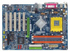
GA-7N400S DDR1 DDR2 DDR3 GA-7N400S/GA-7N400S-L Motherboard Layout KB_MS ATX_12V SOCKET A R_USB ATX COMA LPT COMB USB MIC_IN LINE_OUT LINE_IN LAN* SUR_CEN RTL8100C* SPDIF_IO CODEC F_AUDIO CD_IN AUX_IN nVIDIA nForce 2 Ultra 400 CLK_SW CPU_FAN AGP PCI1 PCI2 PCI3 IDE2 IDE1 nVIDIA nForce 2 MCP RAID SATA1 SATA0 PCI4 BIOS BAT CLR_CMOS PCI5 FDD PWR_LED IR F_USB1 F_USB2 F_PANEL SYS_FAN -L* IT8712 * Only for GA-7N400S-L. - 6 -
GA-7N400S DDR1 DDR2 DDR3 GA-7N400S/GA-7N400S-L Motherboard Layout KB_MS ATX_12V SOCKET A R_USB ATX COMA LPT COMB USB MIC_IN LINE_OUT LINE_IN LAN* SUR_CEN RTL8100C* SPDIF_IO CODEC F_AUDIO CD_IN AUX_IN nVIDIA nForce 2 Ultra 400 CLK_SW CPU_FAN AGP PCI1 PCI2 PCI3 IDE2 IDE1 nVIDIA nForce 2 MCP RAID SATA1 SATA0 PCI4 BIOS BAT CLR_CMOS PCI5 FDD PWR_LED IR F_USB1 F_USB2 F_PANEL SYS_FAN -L* IT8712 * Only for GA-7N400S-L. - 6 -

User Manual
Page 10
...® nForceTM 2 MCP RAID Memory Š 3 DDR DIMM memory slots (supports up to install DDR333 or DDR400 memory module(s). English 1-2 Feature Summary Motherboard Š GA-7N400S or GA-7N400S-L CPU Š Socket A for GA-7N400S-L. (Note) If you want to use DDR memory module(s) with 333Mhz FSB, you install. For example, when using a CPU with frequencies equal... use EasyTune utility, please set Memory Frequency under Advanced Chipset Features to Auto in BIOS Setup (refer to page 34). Line Out (Front Speaker Out) ; GA-7N400S(-L) Motherboard - 10 -
...® nForceTM 2 MCP RAID Memory Š 3 DDR DIMM memory slots (supports up to install DDR333 or DDR400 memory module(s). English 1-2 Feature Summary Motherboard Š GA-7N400S or GA-7N400S-L CPU Š Socket A for GA-7N400S-L. (Note) If you want to use DDR memory module(s) with 333Mhz FSB, you install. For example, when using a CPU with frequencies equal... use EasyTune utility, please set Memory Frequency under Advanced Chipset Features to Auto in BIOS Setup (refer to page 34). Line Out (Front Speaker Out) ; GA-7N400S(-L) Motherboard - 10 -

User Manual
Page 12
... sink manual for heat dissipation or using extreme care when removing the heatsink. Install all the heat sink components (Please refer to prevent CPU overheating. GA-7N400S(-L) Motherboard - 12 - Once the CPU is positioned into it is marked one edge of the heatsink paste. The heatsink may adhere to the CPU lever. To... positioned during installation. 1-4-2 Installation of the Heatsink Fig. 1 Before installing the heat sink, please first add an even layer of heat sink paste on the motherboard so that the CPU pins fit perfectly into its original position.
... sink manual for heat dissipation or using extreme care when removing the heatsink. Install all the heat sink components (Please refer to prevent CPU overheating. GA-7N400S(-L) Motherboard - 12 - Once the CPU is positioned into it is marked one edge of the heatsink paste. The heatsink may adhere to the CPU lever. To... positioned during installation. 1-4-2 Installation of the Heatsink Fig. 1 Before installing the heat sink, please first add an even layer of heat sink paste on the motherboard so that the CPU pins fit perfectly into its original position.

User Manual
Page 14
... 2 memory module 3 memory module DDR 1 DS/SS X DS/SS DDR 2 X DS/SS DS/SS DDR 3 DS/SS DS/SS DS/SS GA-7N400S(-L) Motherboard - 14 - Dual channel memory cannot be used if one must be added to the Channel A slot and the other in the Channel B slot in order... order to operate the Dual Channel Technology, please note the following table is installed. 2. If three DDR memory modules are installed on the same channel. 3. GA-7N400S / GA-7N400S-L includes 3 DIMM sockets as following: Channel A : DDR 1, DDR 2 Channel B : DDR 3 If you want to use memory of Intel chipset specifications. ...
... 2 memory module 3 memory module DDR 1 DS/SS X DS/SS DDR 2 X DS/SS DS/SS DDR 3 DS/SS DS/SS DS/SS GA-7N400S(-L) Motherboard - 14 - Dual channel memory cannot be used if one must be added to the Channel A slot and the other in the Channel B slot in order... order to operate the Dual Channel Technology, please note the following table is installed. 2. If three DDR memory modules are installed on the same channel. 3. GA-7N400S / GA-7N400S-L includes 3 DIMM sockets as following: Channel A : DDR 1, DDR 2 Channel B : DDR 3 If you want to use memory of Intel chipset specifications. ...

User Manual
Page 16
... be connected to Line In jack. MIC In Microphone can use audio software to this connector. You can be connected to MIC In jack. GA-7N400S(-L) Motherboard - 16 - have a standard USB interface. For more information please contact your OS supports USB controller. LAN Port * The provided Internet connection is fast Ethernet, providing ...
... be connected to Line In jack. MIC In Microphone can use audio software to this connector. You can be connected to MIC In jack. GA-7N400S(-L) Motherboard - 16 - have a standard USB interface. For more information please contact your OS supports USB controller. LAN Port * The provided Internet connection is fast Ethernet, providing ...

User Manual
Page 18
... 5 GND 6 VCC 7 GND 8 Power Good 9 5V SB (stand by +5V) 10 +12V 11 3.3V 1 11 12 -12V 13 GND 14 PS_ON(soft on the motherboard and connect tightly. Before connecting the power connector, please make sure that can withstand high power consumption be used that does not provide the required... the power connector with its proper location on /off) 15 GND 16 GND 17 GND 18 -5V 19 VCC 20 VCC GA-7N400S(-L) Motherboard - 18 - The ATX_12V power connector mainly supplies power to start . It is able to all components and devices are properly installed. If a power ...
... 5 GND 6 VCC 7 GND 8 Power Good 9 5V SB (stand by +5V) 10 +12V 11 3.3V 1 11 12 -12V 13 GND 14 PS_ON(soft on the motherboard and connect tightly. Before connecting the power connector, please make sure that can withstand high power consumption be used that does not provide the required... the power connector with its proper location on /off) 15 GND 16 GND 17 GND 18 -5V 19 VCC 20 VCC GA-7N400S(-L) Motherboard - 18 - The ATX_12V power connector mainly supplies power to start . It is able to all components and devices are properly installed. If a power ...

User Manual
Page 20
... IDE cable, and the single IDE cable can then connect to work properly. 1 7 SATA1 1 7 SATA0 Pin No. 1 2 3 4 5 6 7 Definition GND TXP TXN GND RXN RXP GND GA-7N400S(-L) Motherboard - 20 - One IDE connector can connect to one IDE device as Master and the other as Slave (for the Serial ATA and install the proper...
... IDE cable, and the single IDE cable can then connect to work properly. 1 7 SATA1 1 7 SATA0 Pin No. 1 2 3 4 5 6 7 Definition GND TXP TXN GND RXN RXP GND GA-7N400S(-L) Motherboard - 20 - One IDE connector can connect to one IDE device as Master and the other as Slave (for the Serial ATA and install the proper...

User Manual
Page 22
... Close: Power On/Off Pin 1: VCC(+) Pin 2- Pin 3: NC Pin 4: Data(-) Pin 1: LED anode(+) Pin 2: LED cathode(-) Open: Normal Operation Close: Reset Hardware System NC GA-7N400S(-L) Motherboard - 22 - of your chassis front panel to the F_PANEL connector according to the pin assignment below. PW+ PWSPEAK+ SPEAK- 2 20 1 19 HD+ HD- English 10...
... Close: Power On/Off Pin 1: VCC(+) Pin 2- Pin 3: NC Pin 4: Data(-) Pin 1: LED anode(+) Pin 2: LED cathode(-) Open: Normal Operation Close: Reset Hardware System NC GA-7N400S(-L) Motherboard - 22 - of your chassis front panel to the F_PANEL connector according to the pin assignment below. PW+ PWSPEAK+ SPEAK- 2 20 1 19 HD+ HD- English 10...

User Manual
Page 24
... system has digital input function. Use this feature only when your local dealer. 26 15 Pin No. 1 2 3 4 5 6 Definition VCC No Pin SPDIF SPDIFI GND GND GA-7N400S(-L) Motherboard - 24 - Be careful with the polarity of providing digital audio to external speakers or compressed AC3 data to the AUX_IN connector. 1 (CD_IN, black) 1 (AUX_IN, white...
... system has digital input function. Use this feature only when your local dealer. 26 15 Pin No. 1 2 3 4 5 6 Definition VCC No Pin SPDIF SPDIFI GND GND GA-7N400S(-L) Motherboard - 24 - Be careful with the polarity of providing digital audio to external speakers or compressed AC3 data to the AUX_IN connector. 1 (CD_IN, black) 1 (AUX_IN, white...

User Manual
Page 26
To clear CMOS, temporarily short 1-2 pin. Default doesn't include the "Shunter" to its default values by this jumper. Open: Normal 1 Short: Clear CMOS 1 GA-7N400S(-L) Motherboard - 26 - English 18) CLR_CMOS (Clear CMOS) You may clear the CMOS data to prevent from improper use this jumper.
To clear CMOS, temporarily short 1-2 pin. Default doesn't include the "Shunter" to its default values by this jumper. Open: Normal 1 Short: Clear CMOS 1 GA-7N400S(-L) Motherboard - 26 - English 18) CLR_CMOS (Clear CMOS) You may clear the CMOS data to prevent from improper use this jumper.

User Manual
Page 28
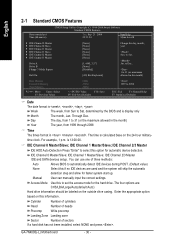
... Disk Type... English The Main Menu (For example: BIOS Ver. : E17) Once you want, please press "Ctrl+F1" to accept or enter the sub-menu. GA-7N400S(-L) Motherboard - 28 - Use arrow keys to select among the items and press to search the advanced option hidden. „ Standard CMOS Features This setup page includes...
... Disk Type... English The Main Menu (For example: BIOS Ver. : E17) Once you want, please press "Ctrl+F1" to accept or enter the sub-menu. GA-7N400S(-L) Motherboard - 28 - Use arrow keys to select among the items and press to search the advanced option hidden. „ Standard CMOS Features This setup page includes...
User Manual
Page 30
... Mode Use this if no IDE devices are : CHS/LBA/Large/Auto(default:Auto) Hard drive information should be labeled on the 24-hour military- GA-7N400S(-L) Motherboard - 30 - is calculated base on the outside drive casing. Cylinder Number of cylinders Head Number of heads Precomp Write precomp Landing Zone Landing zone Sector...
... Mode Use this if no IDE devices are : CHS/LBA/Large/Auto(default:Auto) Hard drive information should be labeled on the 24-hour military- GA-7N400S(-L) Motherboard - 30 - is calculated base on the outside drive casing. Cylinder Number of cylinders Head Number of heads Precomp Write precomp Landing Zone Landing zone Sector...

User Manual
Page 32
...-CDROM Select your boot device priority by Floppy. Note that there will not be any warning message if the drive installed is 360K. (Default value) GA-7N400S(-L) Motherboard - 32 - LS120 Select your boot device priority by USB-FDD. Hard Disk Select your boot device priority by USB-CDROM. USB-FDD Select your boot...
...-CDROM Select your boot device priority by Floppy. Note that there will not be any warning message if the drive installed is 360K. (Default value) GA-7N400S(-L) Motherboard - 32 - LS120 Select your boot device priority by USB-FDD. Hard Disk Select your boot device priority by USB-CDROM. USB-FDD Select your boot...

User Manual
Page 34
... install. Manual Allows full customization of instability. Memory Frequency (Note) By SPD Set memory frequency by SPD. (Default value) 50% ~ 200% Set memory frequency manually. GA-7N400S(-L) Motherboard - 34 - For power end-user use EasyTune utility, please set Memory Frequency to Auto. For example, when using these features may cause your system broken...
... install. Manual Allows full customization of instability. Memory Frequency (Note) By SPD Set memory frequency by SPD. (Default value) 50% ~ 200% Set memory frequency manually. GA-7N400S(-L) Motherboard - 34 - For power end-user use EasyTune utility, please set Memory Frequency to Auto. For example, when using these features may cause your system broken...

User Manual
Page 36
Disabled Disable this function. (Default value) IDE Channel0 Slave RAID Enabled Enable first slave channel IDE RAID function. Disabled Disable this function. (Default value) GA-7N400S(-L) Motherboard - 36 - Disabled Disable this function. (Default value) IDE Channel1 Master RAID Enabled Enable secondary master channel IDE RAID function. Disabled Disable this function. (Default value) ...
Disabled Disable this function. (Default value) IDE Channel0 Slave RAID Enabled Enable first slave channel IDE RAID function. Disabled Disable this function. (Default value) GA-7N400S(-L) Motherboard - 36 - Disabled Disable this function. (Default value) IDE Channel1 Master RAID Enabled Enable secondary master channel IDE RAID function. Disabled Disable this function. (Default value) ...

User Manual
Page 38
.... Disabled Disable this function. ECP Mode Use DMA 3 Set ECP Mode Use DMA to 3. (Default value) 1 Set ECP Mode Use DMA to 10. (Default value) GA-7N400S(-L) Motherboard - 38 - English Onboard Parallel port Disabled Disable onboard LPT port. 378/IRQ7 Enable onboard LPT port and address is 378/IRQ7. (Default value) 278/IRQ5...
.... Disabled Disable this function. ECP Mode Use DMA 3 Set ECP Mode Use DMA to 3. (Default value) 1 Set ECP Mode Use DMA to 10. (Default value) GA-7N400S(-L) Motherboard - 38 - English Onboard Parallel port Disabled Disable onboard LPT port. 378/IRQ7 Enable onboard LPT port and address is 378/IRQ7. (Default value) 278/IRQ5...

User Manual
Page 40
.... English Power On by Keyboard Disabled Disable this function. (Default value) Double Click Double click on PS/2 mouse left button to power on the system. GA-7N400S(-L) Motherboard - 40 -
.... English Power On by Keyboard Disabled Disable this function. (Default value) Double Click Double click on PS/2 mouse left button to power on the system. GA-7N400S(-L) Motherboard - 40 -

User Manual
Page 42
... F10: Save F6: Fail-Save Defaults Current Voltage (V) Vcore / DDR25V / +3.3V / +12V Detect system's voltage status automatically. ESC: Exit F1: General Help F7: Optimized Defaults GA-7N400S(-L) Motherboard - 42 - Current CPU/SYSTEM FAN Speed (RPM) Detect CPU/SYSTEM fan speed status automatically. Current System/CPU Temperature Detect System/CPU temperature automatically.
... F10: Save F6: Fail-Save Defaults Current Voltage (V) Vcore / DDR25V / +3.3V / +12V Detect system's voltage status automatically. ESC: Exit F1: General Help F7: Optimized Defaults GA-7N400S(-L) Motherboard - 42 - Current CPU/SYSTEM FAN Speed (RPM) Detect CPU/SYSTEM fan speed status automatically. Current System/CPU Temperature Detect System/CPU temperature automatically.

User Manual
Page 44
... for entering the BIOS Setup program and having full configuration fields, the User password is rebooted or any time you to eight characters, and press . GA-7N400S(-L) Motherboard - 44 - You will appear to enter Setup. To disable password, just press when you select this field loads the factory defaults for the password every...
... for entering the BIOS Setup program and having full configuration fields, the User password is rebooted or any time you to eight characters, and press . GA-7N400S(-L) Motherboard - 44 - You will appear to enter Setup. To disable password, just press when you select this field loads the factory defaults for the password every...


