
User Manual
Page 6
... Installation Process 13 Step 1: Set System Jumper (CLK_SW)&(CLK_RATIO 14 Step 2: Install the Central Processing Unit (CPU 15 Step 2-1: CPU Installation 15 Step 2-2: CPU Cooling Fan Installation 16 Step 3: Install Memory Modules 17 Step 4: Install expansion cards 20 Step 5: Connect ribbon cables, cabinet wires and power supply 21 Step 5-1: I/O Back Panel Introduction 21 Step 5-2: Connectors Introduction 23 Chapter 3 BIOS Setup 39 The Main Menu (For example: BIOS Ver. : E2 40 Standard CMOS Features 42 N400 Pro2 / N400 Series Motherboard...
... Installation Process 13 Step 1: Set System Jumper (CLK_SW)&(CLK_RATIO 14 Step 2: Install the Central Processing Unit (CPU 15 Step 2-1: CPU Installation 15 Step 2-2: CPU Cooling Fan Installation 16 Step 3: Install Memory Modules 17 Step 4: Install expansion cards 20 Step 5: Connect ribbon cables, cabinet wires and power supply 21 Step 5-1: I/O Back Panel Introduction 21 Step 5-2: Connectors Introduction 23 Chapter 3 BIOS Setup 39 The Main Menu (For example: BIOS Ver. : E2 40 Standard CMOS Features 42 N400 Pro2 / N400 Series Motherboard...
User Manual
Page 8
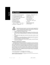
... you do not become alarmed you plug in or remove the ATX power connector on the bag that the ATX power supply is not connected, system cannot boot. j For GA-7N400 Pro2 only. Power cable x 1) IDE cable x 3 / Floppy cable x 1 (j) IDE cable x 1 / Floppy cable x 1(kl) Serial ATA cable x 2 (j) IEEE1394 cable x 1 (j) 2 Port USB Cable x 1 Audio Combo Kit x 1 (j) (SURROUND-Kit + SPDIF Out Kit) I/O Shield Motherboard Settings Label ATX 12V Cable (*) Computer motherboards and expansion cards contain very delicate Integrated Circuit (IC) chips. Use a grounded wrist strap before you can...
... you do not become alarmed you plug in or remove the ATX power connector on the bag that the ATX power supply is not connected, system cannot boot. j For GA-7N400 Pro2 only. Power cable x 1) IDE cable x 3 / Floppy cable x 1 (j) IDE cable x 1 / Floppy cable x 1(kl) Serial ATA cable x 2 (j) IEEE1394 cable x 1 (j) 2 Port USB Cable x 1 Audio Combo Kit x 1 (j) (SURROUND-Kit + SPDIF Out Kit) I/O Shield Motherboard Settings Label ATX 12V Cable (*) Computer motherboards and expansion cards contain very delicate Integrated Circuit (IC) chips. Use a grounded wrist strap before you can...
User Manual
Page 9
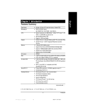
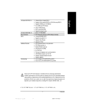
...; 5 PCI slots support 33MHz & PCI 2.2 compliant — 2 IDE controllers provides IDE HDD/CD-ROM (IDE1, IDE2) with PIO, Bus Master (Ultra DMA33/ATA66/ATA100/ATA133) operation modes — IDE3 (j) and IDE4 (j) compatible with RAID, Ultra ATA133/100, IDE — 2 Serial ATA connectors in 150 MB/s operation mode (j) — Controlled by SiI3112 (j) — CPU/System/Power(j) fan revolution detect — CPU/System temperature detect — CPU warning temperature — System voltage detect — CPU/System/Power(j) fan fail warning — CPU Smart Fan control...
...; 5 PCI slots support 33MHz & PCI 2.2 compliant — 2 IDE controllers provides IDE HDD/CD-ROM (IDE1, IDE2) with PIO, Bus Master (Ultra DMA33/ATA66/ATA100/ATA133) operation modes — IDE3 (j) and IDE4 (j) compatible with RAID, Ultra ATA133/100, IDE — 2 Serial ATA connectors in 150 MB/s operation mode (j) — Controlled by SiI3112 (j) — CPU/System/Power(j) fan revolution detect — CPU/System temperature detect — CPU warning temperature — System voltage detect — CPU/System/Power(j) fan fail warning — CPU Smart Fan control...
User Manual
Page 10
... / Game port — Onboard GigaRAID IT8212F chipset — Supports data striping (RAID 0) or mirroring (RAID 1) or striping+mirroring (RAID 0 + RAID 1) — Supports JBOD function — Supports concurrent dual ATA133 IDE controller operation — Support ATAPI mode for HDD — Supports IDE bus master operation — Support ATA133/RAID mode switch by BIOS — Displays status and error checking messages during boot-up — Mirroring supports automatic background rebuilds — Features LBA and Extended Interrupt 13 drive translation in controller onboard BIOS to...
... / Game port — Onboard GigaRAID IT8212F chipset — Supports data striping (RAID 0) or mirroring (RAID 1) or striping+mirroring (RAID 0 + RAID 1) — Supports JBOD function — Supports concurrent dual ATA133 IDE controller operation — Support ATAPI mode for HDD — Supports IDE bus master operation — Support ATA133/RAID mode switch by BIOS — Displays status and error checking messages during boot-up — Mirroring supports automatic background rebuilds — Features LBA and Extended Interrupt 13 drive translation in controller onboard BIOS to...
User Manual
Page 11
... power on your processor's specifications. l For GA-7N400-L only. - 7 - English On-Board SATA RAID (j) On-Board IEEE1394 (j) PS/2 Connector BIOS Additional Features Overclocking — Onboard Silicon Image SiI3112 — Supports Disk striping (RAID0) or DISK Mirroring (RAID1) — Supports UDMA up to 150 MB/sec — AIL UDMA and PIO Modes — Up to set the CPU host frequency in TI TSB43AB23 — PS/2 Keyboard interface and PS/2 Mouse interface — Licensed AWARD BIOS...
... power on your processor's specifications. l For GA-7N400-L only. - 7 - English On-Board SATA RAID (j) On-Board IEEE1394 (j) PS/2 Connector BIOS Additional Features Overclocking — Onboard Silicon Image SiI3112 — Supports Disk striping (RAID0) or DISK Mirroring (RAID1) — Supports UDMA up to 150 MB/sec — AIL UDMA and PIO Modes — Up to set the CPU host frequency in TI TSB43AB23 — PS/2 Keyboard interface and PS/2 Mouse interface — Licensed AWARD BIOS...
User Manual
Page 26
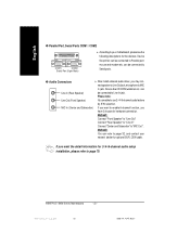
...: Connect "Front Speaker" to "Line Out" Connect "Rear Speaker" to "Line In" Connect "Center and Subwoofer" to use 2-/4-/6-channel audio feature by S/W selection. N400 Pro2 / N400 Series Motherboard - 22 - 7n400pro2_1002_q.p65 22 2003/7/4, ¤U¤È 03:27 Device like CD-ROM,walkman etc. can be connected to Serial ports. y Audio Connectors Line In (Rear Speaker) Line Out (Front Speaker) MIC In (Center and Subwoofer) After install onboard audio driver, you want to enable 6-channel...
...: Connect "Front Speaker" to "Line Out" Connect "Rear Speaker" to "Line In" Connect "Center and Subwoofer" to use 2-/4-/6-channel audio feature by S/W selection. N400 Pro2 / N400 Series Motherboard - 22 - 7n400pro2_1002_q.p65 22 2003/7/4, ¤U¤È 03:27 Device like CD-ROM,walkman etc. can be connected to Serial ports. y Audio Connectors Line In (Rear Speaker) Line Out (Front Speaker) MIC In (Center and Subwoofer) After install onboard audio driver, you want to enable 6-channel...
User Manual
Page 32
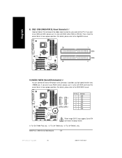
... Pin1. l For GA-7N400-L only. If you high speed transfer rates (150MB/sec). j For GA-7N400 Pro2 only. k For GA-7N400 only. For details, please refer to the GigaRAID manual. 39 1 IDE4 IDE3 40 2 10) SATA0 / SATA1 (Serial ATA Connector)(j) You can connect the Serial ATA device to use IDE3 and IDE4, please use it in unity with BIOS (either RAID or ATA133). N400 Pro2 / N400 Series Motherboard - 28 - 7n400pro2_1002_q...
... Pin1. l For GA-7N400-L only. If you high speed transfer rates (150MB/sec). j For GA-7N400 Pro2 only. k For GA-7N400 only. For details, please refer to the GigaRAID manual. 39 1 IDE4 IDE3 40 2 10) SATA0 / SATA1 (Serial ATA Connector)(j) You can connect the Serial ATA device to use IDE3 and IDE4, please use it in unity with BIOS (either RAID or ATA133). N400 Pro2 / N400 Series Motherboard - 28 - 7n400pro2_1002_q...
User Manual
Page 35
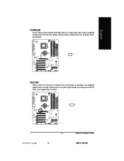
English 14) RAM_LED Do not remove memory modules while RAM_LED is inserted. Informing users that system might cause short or other unexpected damages due to AGP 2X (3.3V) is not supported by voltage. It might not boot up , indicating a non-supported graphics card is on. Remove memory modules only when AC power cord is disconnected. + _ 15) 2X_DET When an AGP 2X (3.3V) card is installed the 4X_AGP will light up normally due to the stand by the chipset. + _ - 31 - 7n400pro2_1002_q.p65 31 Hardware Installation Process 2003/7/4, ¤U¤È 03:27
English 14) RAM_LED Do not remove memory modules while RAM_LED is inserted. Informing users that system might cause short or other unexpected damages due to AGP 2X (3.3V) is not supported by voltage. It might not boot up , indicating a non-supported graphics card is on. Remove memory modules only when AC power cord is disconnected. + _ 15) 2X_DET When an AGP 2X (3.3V) card is installed the 4X_AGP will light up normally due to the stand by the chipset. + _ - 31 - 7n400pro2_1002_q.p65 31 Hardware Installation Process 2003/7/4, ¤U¤È 03:27
User Manual
Page 47
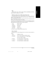
.... There are two types: auto type, and manual type. Auto type which will not work properly if you select User Type, related information will be provided in the computer. Note that the specifications of floppy disk drive A or drive B that has been installed in . English Time The times format in the computer. For example, 1 p.m. is calculated base on the 24-hour military-time clock. Manual type is Enabled). 720K, 3.5" 3.5 inch...
.... There are two types: auto type, and manual type. Auto type which will not work properly if you select User Type, related information will be provided in the computer. Note that the specifications of floppy disk drive A or drive B that has been installed in . English Time The times format in the computer. For example, 1 p.m. is calculated base on the 24-hour military-time clock. Manual type is Enabled). 720K, 3.5" 3.5 inch...
User Manual
Page 53
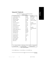
... CMOS Setup Utility-Copyright (C) 1984-2003 Award Software Integrated Peripherals On-Chip Primary PCI IDE [Enabled] Item Help On-Chip Secondary PCI IDE USB Host Controller [Enabled] [V1.1+V2.0] Menu Level u If a hard disk USB Keyboard Support [Disabled] controller card is USB Mouse Support [Disabled] used, set at Disabled AC97 Audio Onboard LAN Chip(jl ) Onboard 1394 (j) Onboard H/W Serial ATA(j) [Auto] [Enabled] [Enabled] [Enabled] [Enabled] Enabled onboard IDE Port Serial ATA Function (j ) Onboard H/W RAID (j) Onboard LAN Boot ROM(jl) Onboard Serial Port 1 [RAID] [Enabled...
... CMOS Setup Utility-Copyright (C) 1984-2003 Award Software Integrated Peripherals On-Chip Primary PCI IDE [Enabled] Item Help On-Chip Secondary PCI IDE USB Host Controller [Enabled] [V1.1+V2.0] Menu Level u If a hard disk USB Keyboard Support [Disabled] controller card is USB Mouse Support [Disabled] used, set at Disabled AC97 Audio Onboard LAN Chip(jl ) Onboard 1394 (j) Onboard H/W Serial ATA(j) [Auto] [Enabled] [Enabled] [Enabled] [Enabled] Enabled onboard IDE Port Serial ATA Function (j ) Onboard H/W RAID (j) Onboard LAN Boot ROM(jl) Onboard Serial Port 1 [RAID] [Enabled...
User Manual
Page 58
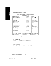
... Power off . N400 Pro2 / N400 Series Motherboard - 54 - 7n400pro2_1001_b.p65 54 2003/7/4, ¤U¤È 03:29 Press power button 4 sec. English Power Management Setup CMOS Setup Utility-Copyright (C) 1984-2003 Award Software Power Management Setup ACPI Suspend Type [S1(POS)] Item Help Soft-Off by PWR-BTTN [Instant-off] Menu Level u PME Event Wake Up [Enabled] [S1] ModemRingOn [Enabled] Set suspend type to S3 Resume by USB [Disabled] Power On Suspend under x KB Power ON Password Enter ACPI...
... Power off . N400 Pro2 / N400 Series Motherboard - 54 - 7n400pro2_1001_b.p65 54 2003/7/4, ¤U¤È 03:29 Press power button 4 sec. English Power Management Setup CMOS Setup Utility-Copyright (C) 1984-2003 Award Software Power Management Setup ACPI Suspend Type [S1(POS)] Item Help Soft-Off by PWR-BTTN [Instant-off] Menu Level u PME Event Wake Up [Enabled] [S1] ModemRingOn [Enabled] Set suspend type to S3 Resume by USB [Disabled] Power On Suspend under x KB Power ON Password Enter ACPI...
User Manual
Page 60
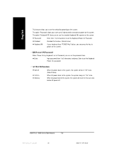
... Series Motherboard - 56 - 7n400pro2_1001_b.p65 56 2003/7/4, ¤U¤È 03:29 Password Enter from 1 to 5 characters) and press Enter to the Last state before AC-power off. AC BACK Function Soft-Off Full-On Memory When AC-power back to the system, the system will return to set the password here. Disabled Disabled this function. (Default value) Keyboard 98 If your keyboard have "POWER Key" button, you...
... Series Motherboard - 56 - 7n400pro2_1001_b.p65 56 2003/7/4, ¤U¤È 03:29 Password Enter from 1 to 5 characters) and press Enter to the Last state before AC-power off. AC BACK Function Soft-Off Full-On Memory When AC-power back to the system, the system will return to set the password here. Disabled Disabled this function. (Default value) Keyboard 98 If your keyboard have "POWER Key" button, you...

User Manual
Page 67
Type the password again and press . You may access all BIOS Setup program function. A message "PASSWORD DISABLED" will appear to eight characters, and press . To disable password, just press when you in creating a password. English Set Supervisor/User Password CMOS Setup Utility-Copyright (C) 1984-2003 Award Software } Standard CMOS Features } Frequency/Voltage Control } Advanced BIOS Features Load Fail-Safe Defaults } Advanced Chipset Features } Integrated PeripheraElsnter Password: Load Optimized Defaults Set Supervisor Password } Power Management Setup Set User ...
Type the password again and press . You may access all BIOS Setup program function. A message "PASSWORD DISABLED" will appear to eight characters, and press . To disable password, just press when you in creating a password. English Set Supervisor/User Password CMOS Setup Utility-Copyright (C) 1984-2003 Award Software } Standard CMOS Features } Frequency/Voltage Control } Advanced BIOS Features Load Fail-Safe Defaults } Advanced Chipset Features } Integrated PeripheraElsnter Password: Load Optimized Defaults Set Supervisor Password } Power Management Setup Set User ...

User Manual
Page 73
... Bios Main ROM Type/Size SST 49LF003A Backup ROM Type/Size SST 49LF003A Wide Range Protection Disable Boot From Main Bios Auto Recovery Enable Halt On Error Disable Keep DMI Data Enable Copy Main ROM Data to Backup Load Default Settings Save Settings to CMOS Q-Flash Utility Update Main BIOS from Floppy Update Backup BIOS from Floppy Save Main BIOS to Floppy Save Backup BIOS to "Enable", the PC will boot from main BIOS or Backup BIOS. Update ESCD failure, checksum error or reset...) occurs in the Main BIOS, just before the Operating System is loaded and after the user...
... Bios Main ROM Type/Size SST 49LF003A Backup ROM Type/Size SST 49LF003A Wide Range Protection Disable Boot From Main Bios Auto Recovery Enable Halt On Error Disable Keep DMI Data Enable Copy Main ROM Data to Backup Load Default Settings Save Settings to CMOS Q-Flash Utility Update Main BIOS from Floppy Update Backup BIOS from Floppy Save Main BIOS to Floppy Save Backup BIOS to "Enable", the PC will boot from main BIOS or Backup BIOS. Update ESCD failure, checksum error or reset...) occurs in the Main BIOS, just before the Operating System is loaded and after the user...
User Manual
Page 74
... to enter the BIOS setting, please press"Del" key when the boot screen appears.) • Halt On Error : Disable(Default), Enable If the BIOS occurs a checksum error or the Main BIOS occurs a WIDE RANGE PROTECTION error and Halt On Error set by system automatically and can't be replaced by user.) • Load Default Settings Load dual BIOS default value. • Save Settings to Main The means that the Main BIOS works normally and could automatically recover the Main BIOS. (This auto recovery utility is set to Enable, the...
... to enter the BIOS setting, please press"Del" key when the boot screen appears.) • Halt On Error : Disable(Default), Enable If the BIOS occurs a checksum error or the Main BIOS occurs a WIDE RANGE PROTECTION error and Halt On Error set by system automatically and can't be replaced by user.) • Load Default Settings Load dual BIOS default value. • Save Settings to Main The means that the Main BIOS works normally and could automatically recover the Main BIOS. (This auto recovery utility is set to Enable, the...
User Manual
Page 78
... the BIOS (ROM) chip itself. 1. DualBIOS™ contains a one -way flash utility will ensure that the correct BIOS (main vs. N400 Pro2 / N400 Series Motherboard - 74 - 7n400pro2_1002_t.p65 74 2003/7/4, ¤U¤È 03:30 In the DualBIOS™ utility, the "Auto Recovery" option will eliminate valuable system down time and costly repair bills cause by BIOS failures. 1. Answer: In today's systems there are virus attacks, BIOS upgrade failures...
... the BIOS (ROM) chip itself. 1. DualBIOS™ contains a one -way flash utility will ensure that the correct BIOS (main vs. N400 Pro2 / N400 Series Motherboard - 74 - 7n400pro2_1002_t.p65 74 2003/7/4, ¤U¤È 03:30 In the DualBIOS™ utility, the "Auto Recovery" option will eliminate valuable system down time and costly repair bills cause by BIOS failures. 1. Answer: In today's systems there are virus attacks, BIOS upgrade failures...
User Manual
Page 94
... RAID IDE controller n Nvidia USB 2.0 Driver Information nVIDIA USB 2.0 Host Controller use Windows Service Pack. For USB2.0 driver support under "Device Manager". You have to resolve the USB device wake up S3 hang up issue in Device Manage. l For GA-7N400-L only. Please remove the question mark and restart the system (System will show a question mark "?" j For GA-7N400 Pro2 only. k For GA-7N400 only. n Realtek 8110S Lan Driver(j) / RealTek LAN Drive(l) Realtek Giga Lan Driver(j) RealTek 10/100 LAN driver for 81xx series chips...
... RAID IDE controller n Nvidia USB 2.0 Driver Information nVIDIA USB 2.0 Host Controller use Windows Service Pack. For USB2.0 driver support under "Device Manager". You have to resolve the USB device wake up S3 hang up issue in Device Manage. l For GA-7N400-L only. Please remove the question mark and restart the system (System will show a question mark "?" j For GA-7N400 Pro2 only. k For GA-7N400 only. n Realtek 8110S Lan Driver(j) / RealTek LAN Drive(l) Realtek Giga Lan Driver(j) RealTek 10/100 LAN driver for 81xx series chips...
User Manual
Page 97
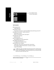
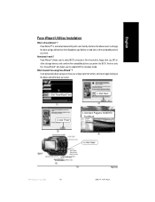
... change the boot-up logo with user-friendly interface that allows users to update BIOS in hard drive, floppy disk, zip, MO or other compatible picture you prefer into BIOS. Click "Finish". (3) 2. Click "Next". (2) 4. Face-WizardTM is Face-Wizard™ ? Click Start/ Programs/ GIGABYTE/ FaceWizard. (4) 5. Click "Help". (5) 7n400pro2_1002_a.p65 93 - 93 - Click "Face-Wizard" item. (1) 3. What's benefit for using Face-Wizard™ ? English Face-Wizard Utilities Installation...
... change the boot-up logo with user-friendly interface that allows users to update BIOS in hard drive, floppy disk, zip, MO or other compatible picture you prefer into BIOS. Click "Finish". (3) 2. Click "Next". (2) 4. Face-WizardTM is Face-Wizard™ ? Click Start/ Programs/ GIGABYTE/ FaceWizard. (4) 5. Click "Help". (5) 7n400pro2_1002_a.p65 93 - 93 - Click "Face-Wizard" item. (1) 3. What's benefit for using Face-Wizard™ ? English Face-Wizard Utilities Installation...
User Manual
Page 98
... problem. However, if the system instability still remains, please clear CMOS to enter BIOS and load Fail-Safe Defaults. 7. Questions 2: Why is equipped with power/amplifier and try again later. If your board has a Clear CMOS jumper, please refer to clear CMOS. Therefore, we suggest that support RAID function after flashing BIOS. Answer: Please make them . If not, please change another speaker with an internal amplifier. Answer: In some options that 's why the light...
... problem. However, if the system instability still remains, please clear CMOS to enter BIOS and load Fail-Safe Defaults. 7. Questions 2: Why is equipped with power/amplifier and try again later. If your board has a Clear CMOS jumper, please refer to clear CMOS. Therefore, we suggest that support RAID function after flashing BIOS. Answer: Please make them . If not, please change another speaker with an internal amplifier. Answer: In some options that 's why the light...
User Manual
Page 99
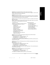
... error 1 long 2 short: Monitor or display card error 3 beeps Base 64K memory failure 1 long 3 short: Keyboard error 4 beeps Timer not operational 1 long 9 short: BIOS ROM error 5 beeps Processor error Continuous long beeps: DRAM error 6 beeps 8042 - Answer:Please set "RAID" to RAID mode or "BASE" to bootup from IDE3, 4 by either RAID or ATA mode? Advanced BIOS features--> First boot device: "SCSI" 3. Question 13: How to set in the BIOS in order to normal ATA mode in the item named Serial ATA function. English Question 8: How do I disable onboard VGA card in order to case...
... error 1 long 2 short: Monitor or display card error 3 beeps Base 64K memory failure 1 long 3 short: Keyboard error 4 beeps Timer not operational 1 long 9 short: BIOS ROM error 5 beeps Processor error Continuous long beeps: DRAM error 6 beeps 8042 - Answer:Please set "RAID" to RAID mode or "BASE" to bootup from IDE3, 4 by either RAID or ATA mode? Advanced BIOS features--> First boot device: "SCSI" 3. Question 13: How to set in the BIOS in order to normal ATA mode in the item named Serial ATA function. English Question 8: How do I disable onboard VGA card in order to case...


