User Manual
Page 1
GA-7BESH-RH Dual Xeon Processor Motherboard USER'S MANUAL XeonTM Processor Motherboard Rev. 1001 12ME-7BESHRH-1001R
GA-7BESH-RH Dual Xeon Processor Motherboard USER'S MANUAL XeonTM Processor Motherboard Rev. 1001 12ME-7BESHRH-1001R
User Manual
Page 2
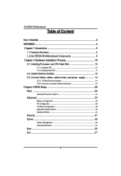
... Motherboard Table of Content Item Checklist 4 WARNING 4 Chapter 1 Introduction 5 1.1 Features Summary 5 1.2 GA-7BESH-RH Motherboard Components 8 Chapter 2 Hardware Installation Process 10 2-1: Installing Processor and CPU Haet Sink 10 2-1-1: Installing CPU ...10 2-1-2: Installing Heat Sink 11 2-2: Install memory modules ...
... Motherboard Table of Content Item Checklist 4 WARNING 4 Chapter 1 Introduction 5 1.1 Features Summary 5 1.2 GA-7BESH-RH Motherboard Components 8 Chapter 2 Hardware Installation Process 10 2-1: Installing Processor and CPU Haet Sink 10 2-1-1: Installing CPU ...10 2-1-2: Installing Heat Sink 11 2-2: Install memory modules ...
User Manual
Page 4
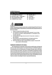
... motherboard IDE (ATA100 ) cable x 1 / Floppy cable x 1 CD for motherboard driver & utility GA-7BESH-RH user's manual Serial ATA cable x 4 I/O Shield Kit Power cable x 4 SCSI cable x 1 WARNING! Sometimes you may need to use the plastic springs to isolate the ...
... motherboard IDE (ATA100 ) cable x 1 / Floppy cable x 1 CD for motherboard driver & utility GA-7BESH-RH user's manual Serial ATA cable x 4 I/O Shield Kit Power cable x 4 SCSI cable x 1 WARNING! Sometimes you may need to use the plastic springs to isolate the ...

User Manual
Page 6
English GA-7BESH-RH Motherboard On-Board Peripherals Hardware Monitor On-Board LAN Hardware Monitor BIOS Special Features Additional Features 1 ATA 100 connector 1 Floppyport supports 360K, 720K,1.2M, 1....
English GA-7BESH-RH Motherboard On-Board Peripherals Hardware Monitor On-Board LAN Hardware Monitor BIOS Special Features Additional Features 1 ATA 100 connector 1 Floppyport supports 360K, 720K,1.2M, 1....
User Manual
Page 8
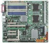
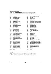
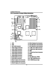
... Connector 15. FBD DIMM C1/C2 37. RJ45 LAN/USB ports 39. COM Port 42. ibutton** ** ibutton functions for LSI Software RAID 0,1,5,10 8 English GA-7BESH-RH Motherboard 1.2 GA-7BESH-RH Motherboard Components 1. Primary CPU 2. Intel ESB2E 5. Adaptec AIC-7901 6. BIOS Flash 8. Intel LAN chip 12. Floppy Connector 17. SATA2 Connector 22. SATA4 Connector...
... Connector 15. FBD DIMM C1/C2 37. RJ45 LAN/USB ports 39. COM Port 42. ibutton** ** ibutton functions for LSI Software RAID 0,1,5,10 8 English GA-7BESH-RH Motherboard 1.2 GA-7BESH-RH Motherboard Components 1. Primary CPU 2. Intel ESB2E 5. Adaptec AIC-7901 6. BIOS Flash 8. Intel LAN chip 12. Floppy Connector 17. SATA2 Connector 22. SATA4 Connector...
User Manual
Page 10
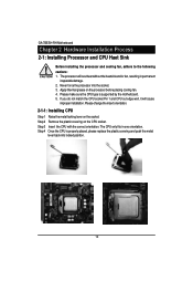
... the metal locking lever on the CPU socket. Step 2 Remove the plastic covering on the socket. The CPU only fits in permanent irreparable damage. 2. English GA-7BESH-RH Motherboard Chapter 2 Hardware Installation Process 2-1: Installing Processor and CPU Haet Sink Before installing the processor and cooling fan, adhere to the following cautions: 1. Never...
... the metal locking lever on the CPU socket. Step 2 Remove the plastic covering on the socket. The CPU only fits in permanent irreparable damage. 2. English GA-7BESH-RH Motherboard Chapter 2 Hardware Installation Process 2-1: Installing Processor and CPU Haet Sink Before installing the processor and cooling fan, adhere to the following cautions: 1. Never...
User Manual
Page 12
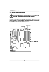
English GA-7BESH-RH Motherboard 2-2: Install memory modules Before installing the processor and heatsink, adhere to the following warning: When DIMM LED is ON, do not install/remove DIMM from socket. The BIOS will automatically detects memory type and size during system boot. It supports the 4 FB-DIMM Channels Technology. For detail DIMM installation, please refer to the following instructions. DIMMC1/C2 DIMMA1/A2 DIMMB1/B2 DIMMD1/D2 12 GA-7BESH-RH has 8 dual inline memory module (DIMM) sokcets.
English GA-7BESH-RH Motherboard 2-2: Install memory modules Before installing the processor and heatsink, adhere to the following warning: When DIMM LED is ON, do not install/remove DIMM from socket. The BIOS will automatically detects memory type and size during system boot. It supports the 4 FB-DIMM Channels Technology. For detail DIMM installation, please refer to the following instructions. DIMMC1/C2 DIMMA1/A2 DIMMB1/B2 DIMMD1/D2 12 GA-7BESH-RH has 8 dual inline memory module (DIMM) sokcets.
User Manual
Page 14
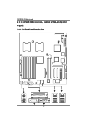
English GA-7BESH-RH Motherboard 2-3: Connect ribbon cables, cabinet wires, and power supply 2-3-1 : I/O Back Panel Introduction 14
English GA-7BESH-RH Motherboard 2-3: Connect ribbon cables, cabinet wires, and power supply 2-3-1 : I/O Back Panel Introduction 14
User Manual
Page 16
FDD1 (Floppy Connector) 5. CPU_FAN2 (CPU 2 Fan Connector) 18. F_Panel (Front Panel Connector) 22. GA-7BESH-RH Motherboard 2-3-2 :Connectors & Jumper Setting Introduction English 21 22 20 4 23 11 17 15 14 1 2 16 10 9 8 6 5 12 7 24 26 25 18 19 3 13 1. ATX1 2. ...
FDD1 (Floppy Connector) 5. CPU_FAN2 (CPU 2 Fan Connector) 18. F_Panel (Front Panel Connector) 22. GA-7BESH-RH Motherboard 2-3-2 :Connectors & Jumper Setting Introduction English 21 22 20 4 23 11 17 15 14 1 2 16 10 9 8 6 5 12 7 24 26 25 18 19 3 13 1. ATX1 2. ...
User Manual
Page 18
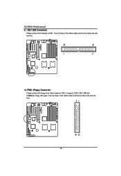
The red stripe of the ribbon cable must be the same side with the Pin1. 39 40 1 2 4 ) FDD1 (Floppy Connector) Please connect the floppy drive ribbon cables to IDE1. The red stripe of the ribbon cable must be the same side with the Pin1. 21 34 33 18 It supports 720K,1.2M,1.44M and 2.88Mbytes floppy disk types. English GA-7BESH-RH Motherboard 3 ) IDE1 (IDE Connector) Please connect first harddisk to FDD.
The red stripe of the ribbon cable must be the same side with the Pin1. 39 40 1 2 4 ) FDD1 (Floppy Connector) Please connect the floppy drive ribbon cables to IDE1. The red stripe of the ribbon cable must be the same side with the Pin1. 21 34 33 18 It supports 720K,1.2M,1.44M and 2.88Mbytes floppy disk types. English GA-7BESH-RH Motherboard 3 ) IDE1 (IDE Connector) Please connect first harddisk to FDD.
User Manual
Page 20
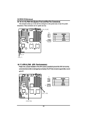
English GA-7BESH-RH Motherboard 12/ 13/ 14/ 15 ) FAN 1/2/3 (System Front and Rear Fan Connectors) This connector allows you to link with the cooling fan on the ...
English GA-7BESH-RH Motherboard 12/ 13/ 14/ 15 ) FAN 1/2/3 (System Front and Rear Fan Connectors) This connector allows you to link with the cooling fan on the ...
User Manual
Page 22
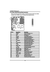
... Clock ID Switch Signal cathode(-) Chassis intrusion Signal ID Switch Ground LAN2 access LED Signal NMI Switch cathode(-) LAN2 linked LED Signal cathode(-) 22 English GA-7BESH-RH Motherboard 21 ) F_Panel (2X12 Pins Front Panel connector) Please connect the power LED, PC speaker, reset switch and power switch of your chassis front...
... Clock ID Switch Signal cathode(-) Chassis intrusion Signal ID Switch Ground LAN2 access LED Signal NMI Switch cathode(-) LAN2 linked LED Signal cathode(-) 22 English GA-7BESH-RH Motherboard 21 ) F_Panel (2X12 Pins Front Panel connector) Please connect the power LED, PC speaker, reset switch and power switch of your chassis front...
User Manual
Page 24
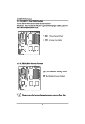
Default value doesn't include the "Shunter" to its default values by this jumper. To clear CMOS, temporarily short 1-2 pin. 1 1-2 close: Normal (Default) 1 2-3 close: Clear CMOS 25 ) JP_REC1 ( BIOS Recovery Function) Open: Enable BIOS Recovery function. Short: Disable this jumper. English GA-7BESH-RH Motherboard 24 ) CLR_CMOS1 (Clear CMOS Function) You may clear the CMOS data to prevent from improper use this function. (Default) Please remove the jumper when system access recovery flopp disk. 24
Default value doesn't include the "Shunter" to its default values by this jumper. To clear CMOS, temporarily short 1-2 pin. 1 1-2 close: Normal (Default) 1 2-3 close: Clear CMOS 25 ) JP_REC1 ( BIOS Recovery Function) Open: Enable BIOS Recovery function. Short: Disable this jumper. English GA-7BESH-RH Motherboard 24 ) CLR_CMOS1 (Clear CMOS Function) You may clear the CMOS data to prevent from improper use this function. (Default) Please remove the jumper when system access recovery flopp disk. 24
User Manual
Page 26
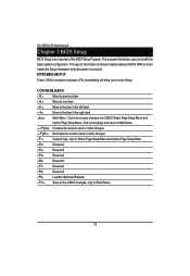
CONTROL KEYS Move to previous item Move to next item Move to the item in the left hand Move to enter Setup. GA-7BESH-RH Motherboard Chapter 3 BIOS Setup BIOS Setup is turned off. ENTERINGSETUP Power ON the computer and press immediately will allow you to the item in ...
CONTROL KEYS Move to previous item Move to next item Move to the item in the left hand Move to enter Setup. GA-7BESH-RH Motherboard Chapter 3 BIOS Setup BIOS Setup is turned off. ENTERINGSETUP Power ON the computer and press immediately will allow you to the item in ...
User Manual
Page 28
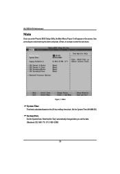
Set the System Time (HH:MM:SS) System Date Set the System Date. Note that the "Day" automatically changed after you enter Phoenix BIOS Setup Utility, the Main Menu (Figure 1) will appear on the 24-hour military time clock. Use arrow keys to select among the items and press to accept or enter the sub-menu. Figure 1: Main System Time The time is calculated based on the screen. GA-7BESH-RH Motherboard Main Once you set the date. (Weekend: DD: MM: YY) (YY: 1099~2099) 28
Set the System Time (HH:MM:SS) System Date Set the System Date. Note that the "Day" automatically changed after you enter Phoenix BIOS Setup Utility, the Main Menu (Figure 1) will appear on the 24-hour military time clock. Use arrow keys to select among the items and press to accept or enter the sub-menu. Figure 1: Main System Time The time is calculated based on the screen. GA-7BESH-RH Motherboard Main Once you set the date. (Weekend: DD: MM: YY) (YY: 1099~2099) 28
User Manual
Page 30
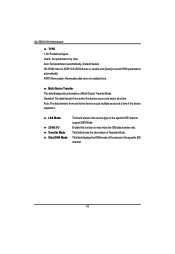
... Multi-Sector Transfer Mode. ATAPI Removable: Removable disk drive is installed here. Users: Set parameters by User. This field shows the information of Teansfer Mode. GA-7BESH-RH Motherboard TYPE 1-39: Predefined types. Disabled: The data transfer from and to the device occurs one sector at a time if the device supports it...
... Multi-Sector Transfer Mode. ATAPI Removable: Removable disk drive is installed here. Users: Set parameters by User. This field shows the information of Teansfer Mode. GA-7BESH-RH Motherboard TYPE 1-39: Predefined types. Disabled: The data transfer from and to the device occurs one sector at a time if the device supports it...
User Manual
Page 32
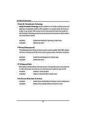
... results in the physical processor have entered the C1 state, the processor will allow a platform to run multiple operating systems and applications in independent partitions. GA-7BESH-RH Motherboard Intel (R) Virtualization Technology Intel(R) Virtualization Technology will reduce the core clock frequency to system bus ratio and VID.
... results in the physical processor have entered the C1 state, the processor will allow a platform to run multiple operating systems and applications in independent partitions. GA-7BESH-RH Motherboard Intel (R) Virtualization Technology Intel(R) Virtualization Technology will reduce the core clock frequency to system bus ratio and VID.

User Manual
Page 34
Save the changes and restart system. Disable this function. (Default value) 34 After rebooting system, the Memory Reset item will clear the memory error status. Memory Reset Yes No Select 'Yes', system will set to 'No' automatically. GA-7BESH-RH Motherboard Memory Configuration Figure 2-1: Memory Configuration System Memory/Extended Memory/DIMMGroup 1~8 Status These category is display-only which is determined by POST (Power On Self Test) of the BIOS.
Save the changes and restart system. Disable this function. (Default value) 34 After rebooting system, the Memory Reset item will clear the memory error status. Memory Reset Yes No Select 'Yes', system will set to 'No' automatically. GA-7BESH-RH Motherboard Memory Configuration Figure 2-1: Memory Configuration System Memory/Extended Memory/DIMMGroup 1~8 Status These category is display-only which is determined by POST (Power On Self Test) of the BIOS.
User Manual
Page 36
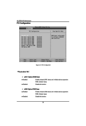
LAN2 Option ROM Scan Enabled Enable onboard LAN2 device and initialize device expansion ROM. (Default value) Disabled Disable this function. GA-7BESH-RH Motherboard PCI Configuration Figure 2-2: PCI Configuration Embedded NIC LAN 1 Option ROM Scan Enabled Enable onboard LAN1 device and initialize device expansion ROM. (Default value) Disabled Disable this function. 36
LAN2 Option ROM Scan Enabled Enable onboard LAN2 device and initialize device expansion ROM. (Default value) Disabled Disable this function. GA-7BESH-RH Motherboard PCI Configuration Figure 2-2: PCI Configuration Embedded NIC LAN 1 Option ROM Scan Enabled Enable onboard LAN1 device and initialize device expansion ROM. (Default value) Disabled Disable this function. 36
User Manual
Page 38
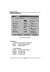
GA-7BESH-RH Motherboard I/O Device Configuration Figure 2-3: I /O Address/IRQ 3F8/IRQ4 Set IO address to 3F8. (Default value) 2F8/IRQ3 Set IO address to 2F8. 3E8/IRQ4 Set IO address to 3E8. 2E8/IRQ3 Set IO address to configure serial prot A by using this option. Base I /O Device Configuration Serial Port A This allows users to 2E8. 38 Enabled Enable the configuration (Default value) Disabled Disable the configuration.
GA-7BESH-RH Motherboard I/O Device Configuration Figure 2-3: I /O Address/IRQ 3F8/IRQ4 Set IO address to 3F8. (Default value) 2F8/IRQ3 Set IO address to 2F8. 3E8/IRQ4 Set IO address to 3E8. 2E8/IRQ3 Set IO address to configure serial prot A by using this option. Base I /O Device Configuration Serial Port A This allows users to 2E8. 38 Enabled Enable the configuration (Default value) Disabled Disable the configuration.

