User Manual
Page 2
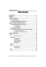
... 5 1.2 GA-7BESH-RH Motherboard Components 8 Chapter 2 Hardware Installation Process 10 2-1: Installing Processor and CPU Haet Sink 10 2-1-1: Installing CPU ...10 2-1-2: Installing Heat Sink 11 2-2: Install memory modules 12 2-3: Connect ribbon cables, cabinet wires, and power supply 14 2-3-1 : I/O Back Panel Introduction 14 2-3-2 :Connectors & Jumper Setting Introduction 16 Chapter 3 BIOS Setup 26 Main ...28 Advanced Processor Options 31 Advanced 33 Memory Configuration ...34 PCI Configuration ...36 I/O Device Configuration 38 Advanced Chipset Control 42 Hardware Monitor ...44...
... 5 1.2 GA-7BESH-RH Motherboard Components 8 Chapter 2 Hardware Installation Process 10 2-1: Installing Processor and CPU Haet Sink 10 2-1-1: Installing CPU ...10 2-1-2: Installing Heat Sink 11 2-2: Install memory modules 12 2-3: Connect ribbon cables, cabinet wires, and power supply 14 2-3-1 : I/O Back Panel Introduction 14 2-3-2 :Connectors & Jumper Setting Introduction 16 Chapter 3 BIOS Setup 26 Main ...28 Advanced Processor Options 31 Advanced 33 Memory Configuration ...34 PCI Configuration ...36 I/O Device Configuration 38 Advanced Chipset Control 42 Hardware Monitor ...44...
User Manual
Page 3
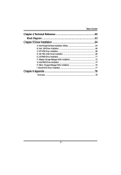
AIC-790x SCSI Driver Installation 69 E. English Table of Content Chapter 4 Technical Reference 63 Block Diagram 63 Chapter 5 Driver Installation 64 A. Intel LAN Driver Installation 66 C. DirectX 9.0C Driver Installation 77 Chapter 6 Appendix 78 Acronyms ...78 3 Intel Chipset Software Installation Utilities 64 B. LSI RAID Driver Installation 71 F. Adaptec Storage Manager Utility Installation 72 G. Intel RAID Driver Installation 74 H. Matrix Storgae Manager Utility Installation 75 I. ATI VGA Driver Installation 68 D.
AIC-790x SCSI Driver Installation 69 E. English Table of Content Chapter 4 Technical Reference 63 Block Diagram 63 Chapter 5 Driver Installation 64 A. Intel LAN Driver Installation 66 C. DirectX 9.0C Driver Installation 77 Chapter 6 Appendix 78 Acronyms ...78 3 Intel Chipset Software Installation Utilities 64 B. LSI RAID Driver Installation 71 F. Adaptec Storage Manager Utility Installation 72 G. Intel RAID Driver Installation 74 H. Matrix Storgae Manager Utility Installation 75 I. ATI VGA Driver Installation 68 D.
User Manual
Page 4
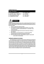
... be a little hard to attach the spacers, do not have one, touch both of your computer. 1. Sometimes you can still attach the motherboard to the chassis... Unplug your hands to a safely grounded object or to the mounting holes. English GA-7BESH-RH Motherboard Item Checklist The GA-7BESH-RH motherboard IDE (ATA100 ) cable x 1 / Floppy cable x 1 CD for motherboard driver & utility GA-7BESH-RH user's manual Serial ATA cable x 4 I/O Shield Kit Power cable x 4 SCSI cable x 1 WARNING! Just...
... be a little hard to attach the spacers, do not have one, touch both of your computer. 1. Sometimes you can still attach the motherboard to the chassis... Unplug your hands to a safely grounded object or to the mounting holes. English GA-7BESH-RH Motherboard Item Checklist The GA-7BESH-RH motherboard IDE (ATA100 ) cable x 1 / Floppy cable x 1 CD for motherboard driver & utility GA-7BESH-RH user's manual Serial ATA cable x 4 I/O Shield Kit Power cable x 4 SCSI cable x 1 WARNING! Just...
User Manual
Page 5
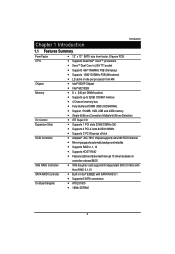
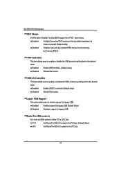
... and 4GB memory Single-bit Errors Correction, Multiple-bit Errors Detection ITE Super I/O Supports 1 PCI slots 32-Bit/33MHz (5V) Supports 2 PCI-X slots 64-Bit/100MHz Supports 3 PCI-Express x8 slot Adaptec® AIC-7901 chipset supports ultra 320 SCSI channel Mirroring supports automatic background rebuilds Supports RAID 0 ,1, 10 Supports HOST RAID Features LBA and Extended Interrupt 13 drive translation in controller onboard BIOS SAS daughter card supports 8 independant SAS 3.0 Gb/s with Host RAID 0,1,10 Built in Intel® ESB2E with SATA RAID 0,1 Supports 6 SATA connectors ATI...
... and 4GB memory Single-bit Errors Correction, Multiple-bit Errors Detection ITE Super I/O Supports 1 PCI slots 32-Bit/33MHz (5V) Supports 2 PCI-X slots 64-Bit/100MHz Supports 3 PCI-Express x8 slot Adaptec® AIC-7901 chipset supports ultra 320 SCSI channel Mirroring supports automatic background rebuilds Supports RAID 0 ,1, 10 Supports HOST RAID Features LBA and Extended Interrupt 13 drive translation in controller onboard BIOS SAS daughter card supports 8 independant SAS 3.0 Gb/s with Host RAID 0,1,10 Built in Intel® ESB2E with SATA RAID 0,1 Supports 6 SATA connectors ATI...

User Manual
Page 6
... GA-7BESH-RH Motherboard On-Board Peripherals Hardware Monitor On-Board LAN Hardware Monitor BIOS Special Features Additional Features 1 ATA 100 connector 1 Floppyport supports 360K, 720K,1.2M, 1.44M and 2.88M bytes. 2 PS/2 connectors 1 Parallel port supports Normal/EPP/ECP mode 2 Serial port (COM, 1 by cable) 7 x USB 2.0 (3 by cable) 1 VGA connector 2 x LAN RJ45 6 x SATA connectors CPU/Power/System Fan Revolution Detect CPU shutdown when overheat System Voltage Detect Build in Intel® ESB2E chipset supports dual Gigabit Ethernet ports Supports WOL, PXE Flexible hardware design to switch...
... GA-7BESH-RH Motherboard On-Board Peripherals Hardware Monitor On-Board LAN Hardware Monitor BIOS Special Features Additional Features 1 ATA 100 connector 1 Floppyport supports 360K, 720K,1.2M, 1.44M and 2.88M bytes. 2 PS/2 connectors 1 Parallel port supports Normal/EPP/ECP mode 2 Serial port (COM, 1 by cable) 7 x USB 2.0 (3 by cable) 1 VGA connector 2 x LAN RJ45 6 x SATA connectors CPU/Power/System Fan Revolution Detect CPU shutdown when overheat System Voltage Detect Build in Intel® ESB2E chipset supports dual Gigabit Ethernet ports Supports WOL, PXE Flexible hardware design to switch...
User Manual
Page 8
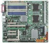
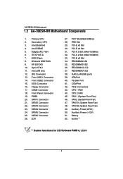
.../2 Connectors 43. FAN 1 (System Front Fan) 46. Battery 52. ibutton** ** ibutton functions for LSI Software RAID 0,1,5,10 8 Adaptec AIC-7901 6. Front USB2 Connector 15. ZCR 27. PCI-E x8 Slot 34. VGA Port 40. FAN 2 (SystemFront Fan) 47. Auxiliary Power (+12V) 51. Winbond W83792G 9. COM2 Connector 18. PCI-E x8 Slot 30. CPU 1 FAN 43. FAN R1 (System Rear Fan) 48. English GA-7BESH-RH Motherboard 1.2 GA-7BESH-RH Motherboard Components 1. Intel LAN chip 12. SATA2 Connector 22. SATA3 Connector 23. SATA6 Connector 26. BIOS Flash...
.../2 Connectors 43. FAN 1 (System Front Fan) 46. Battery 52. ibutton** ** ibutton functions for LSI Software RAID 0,1,5,10 8 Adaptec AIC-7901 6. Front USB2 Connector 15. ZCR 27. PCI-E x8 Slot 34. VGA Port 40. FAN 2 (SystemFront Fan) 47. Auxiliary Power (+12V) 51. Winbond W83792G 9. COM2 Connector 18. PCI-E x8 Slot 30. CPU 1 FAN 43. FAN R1 (System Rear Fan) 48. English GA-7BESH-RH Motherboard 1.2 GA-7BESH-RH Motherboard Components 1. Intel LAN chip 12. SATA2 Connector 22. SATA3 Connector 23. SATA6 Connector 26. BIOS Flash...
User Manual
Page 10
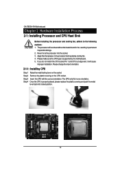
... replace the plastic covering and push the metal lever back into the socket. 3. Step 3 Insert the CPU with the correct orientation. If you do not match the CPU socket Pin 1 and CPU cut edge well, it will overheat without the heatsink and/or fan, resulting in one orientation. The processor will cause improper installation. English GA-7BESH-RH Motherboard Chapter 2 Hardware Installation Process 2-1: Installing Processor and CPU Haet...
... replace the plastic covering and push the metal lever back into the socket. 3. Step 3 Insert the CPU with the correct orientation. If you do not match the CPU socket Pin 1 and CPU cut edge well, it will overheat without the heatsink and/or fan, resulting in one orientation. The processor will cause improper installation. English GA-7BESH-RH Motherboard Chapter 2 Hardware Installation Process 2-1: Installing Processor and CPU Haet...
User Manual
Page 12
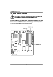
For detail DIMM installation, please refer to the following instructions. DIMMC1/C2 DIMMA1/A2 DIMMB1/B2 DIMMD1/D2 12 It supports the 4 FB-DIMM Channels Technology. The BIOS will automatically detects memory type and size during system boot. GA-7BESH-RH has 8 dual inline memory module (DIMM) sokcets. English GA-7BESH-RH Motherboard 2-2: Install memory modules Before installing the processor and heatsink, adhere to the following warning: When DIMM LED is ON, do not install/remove DIMM from socket.
For detail DIMM installation, please refer to the following instructions. DIMMC1/C2 DIMMA1/A2 DIMMB1/B2 DIMMD1/D2 12 It supports the 4 FB-DIMM Channels Technology. The BIOS will automatically detects memory type and size during system boot. GA-7BESH-RH has 8 dual inline memory module (DIMM) sokcets. English GA-7BESH-RH Motherboard 2-2: Install memory modules Before installing the processor and heatsink, adhere to the following warning: When DIMM LED is ON, do not install/remove DIMM from socket.
User Manual
Page 17
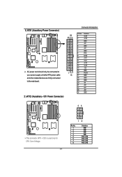
1) ATX1 (Auxukiary Power Connector) 24 12 AC power cord should only be connected to 1 your power supply unit after ATX power cable 13 and other related devices are firmly connected to the mainboard. 2 ) ATX2 (Auxukiary +12V Power Connector) Connector Introduction PIN No. 1 2 3 4 ...5 6 7 8 9 10 11 12 13 14 15 16 17 18 19 20 21 22 23 24 Definition +3.3V +3.3V GND +5V GND +5V GND POK 5VSB +12V +12V +3.3V +3.3V -12V GND PSON GND GND GND -5V +5V +5V +5V GND 45 This connector (ATX +12V) is used only for CPU Core Voltage. 17 18 Pin...
1) ATX1 (Auxukiary Power Connector) 24 12 AC power cord should only be connected to 1 your power supply unit after ATX power cable 13 and other related devices are firmly connected to the mainboard. 2 ) ATX2 (Auxukiary +12V Power Connector) Connector Introduction PIN No. 1 2 3 4 ...5 6 7 8 9 10 11 12 13 14 15 16 17 18 19 20 21 22 23 24 Definition +3.3V +3.3V GND +5V GND +5V GND POK 5VSB +12V +12V +3.3V +3.3V -12V GND PSON GND GND GND -5V +5V +5V +5V GND 45 This connector (ATX +12V) is used only for CPU Core Voltage. 17 18 Pin...
User Manual
Page 20
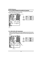
English GA-7BESH-RH Motherboard 12/ 13/ 14/ 15 ) FAN 1/2/3 (System Front and Rear Fan Connectors) This connector allows you to link with the cooling fan on the system case to prevent the CPU from running under abnormal condition or damaged by overheating.The CPU fan connector supports Max. FAN_R1&R2 1 1 Pin No. 1 2 3 4 Definition GND 12V Sense Control FAN_F2 FAN_F1 16/ 17 ) CPU1/2_FAN (CPU Fan Connectors) Please note, a proper installation of...
English GA-7BESH-RH Motherboard 12/ 13/ 14/ 15 ) FAN 1/2/3 (System Front and Rear Fan Connectors) This connector allows you to link with the cooling fan on the system case to prevent the CPU from running under abnormal condition or damaged by overheating.The CPU fan connector supports Max. FAN_R1&R2 1 1 Pin No. 1 2 3 4 Definition GND 12V Sense Control FAN_F2 FAN_F1 16/ 17 ) CPU1/2_FAN (CPU Fan Connectors) Please note, a proper installation of...
User Manual
Page 22
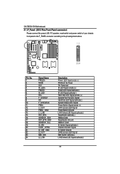
.... 24. Description Power LED Signal anode (+) P5VStand By Power Pin Removed ID LED Signal anode (+) Power LED Signal cathode(-) ID LED Signal cathode(-) Hard Disk LED Signal anode (+) System Fan Fail LED Signal Hard Disk LED Signal cathode(-) System Status LED Signal Power Button Signal anode (+) LAN1 access LED Signal Power Button Ground LAN1 linked LED Signal cathode(-) Reset Button cathode(-) SMBus Data Reset Button Ground SMBus Clock ID Switch Signal cathode(-) Chassis intrusion Signal ID Switch Ground LAN2 access LED Signal NMI Switch cathode(-) LAN2...
.... 24. Description Power LED Signal anode (+) P5VStand By Power Pin Removed ID LED Signal anode (+) Power LED Signal cathode(-) ID LED Signal cathode(-) Hard Disk LED Signal anode (+) System Fan Fail LED Signal Hard Disk LED Signal cathode(-) System Status LED Signal Power Button Signal anode (+) LAN1 access LED Signal Power Button Ground LAN1 linked LED Signal cathode(-) Reset Button cathode(-) SMBus Data Reset Button Ground SMBus Clock ID Switch Signal cathode(-) Chassis intrusion Signal ID Switch Ground LAN2 access LED Signal NMI Switch cathode(-) LAN2...
User Manual
Page 24
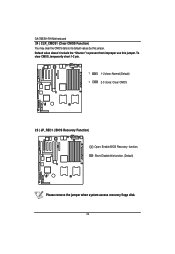
Short: Disable this jumper. To clear CMOS, temporarily short 1-2 pin. 1 1-2 close: Normal (Default) 1 2-3 close: Clear CMOS 25 ) JP_REC1 ( BIOS Recovery Function) Open: Enable BIOS Recovery function. English GA-7BESH-RH Motherboard 24 ) CLR_CMOS1 (Clear CMOS Function) You may clear the CMOS data to prevent from improper use this jumper. Default value doesn't include the "Shunter" to its default values by this function. (Default) Please remove the jumper when system access recovery flopp disk. 24
Short: Disable this jumper. To clear CMOS, temporarily short 1-2 pin. 1 1-2 close: Normal (Default) 1 2-3 close: Clear CMOS 25 ) JP_REC1 ( BIOS Recovery Function) Open: Enable BIOS Recovery function. English GA-7BESH-RH Motherboard 24 ) CLR_CMOS1 (Clear CMOS Function) You may clear the CMOS data to prevent from improper use this jumper. Default value doesn't include the "Shunter" to its default values by this function. (Default) Please remove the jumper when system access recovery flopp disk. 24
User Manual
Page 26
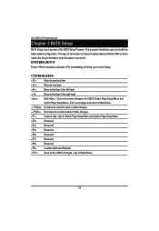
... information is stored in the left hand Move to modify the basic system configuration. Quit and not save changes into CMOS Status Page Setup Menu and Option Page Setup Menu - CONTROL KEYS Move to previous item Move to next item Move to the item in battery-backed CMOS RAM so that allows users to the item in the right hand Main Menu - GA-7BESH-RH Motherboard Chapter 3 BIOS Setup BIOS Setup is turned off.
... information is stored in the left hand Move to modify the basic system configuration. Quit and not save changes into CMOS Status Page Setup Menu and Option Page Setup Menu - CONTROL KEYS Move to previous item Move to next item Move to the item in battery-backed CMOS RAM so that allows users to the item in the right hand Main Menu - GA-7BESH-RH Motherboard Chapter 3 BIOS Setup BIOS Setup is turned off.
User Manual
Page 29
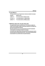
.../2 in. 31/2 inch double-sided drive; 720K byte capacity 1.44M, 31/2 in. 31/2 inch double-sided drive; 1.44M byte capacity. 2.88M, 31/2 in the computer. BIOS Setup Legacy Diskette A This category identifies the type of floppy disk drive A that has been installed in the documentation form your drive must match with the drive table. There are two types: auto type, and manual type. The hard disk will automatically detect HDD type.
.../2 in. 31/2 inch double-sided drive; 720K byte capacity 1.44M, 31/2 in. 31/2 inch double-sided drive; 1.44M byte capacity. 2.88M, 31/2 in the computer. BIOS Setup Legacy Diskette A This category identifies the type of floppy disk drive A that has been installed in the documentation form your drive must match with the drive table. There are two types: auto type, and manual type. The hard disk will automatically detect HDD type.
User Manual
Page 30
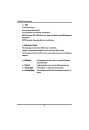
... Removable: Removable disk drive is installed here. Enable this function to set all HDD parameters automatically. Disabled: The data transfer from and to the device occurs one sector at a time if the device supports it. GA-7BESH-RH Motherboard TYPE 1-39: Predefined types. This field shows the information of Multi-Sector Transfer Mode. Users: Set parameters by User. Multi-Sector Transfer This field displays the information of Teansfer Mode. Auto: Set parameters automatically. (Default Vaules) CD-ROM: Use...
... Removable: Removable disk drive is installed here. Enable this function to set all HDD parameters automatically. Disabled: The data transfer from and to the device occurs one sector at a time if the device supports it. GA-7BESH-RH Motherboard TYPE 1-39: Predefined types. This field shows the information of Multi-Sector Transfer Mode. Users: Set parameters by User. Multi-Sector Transfer This field displays the information of Teansfer Mode. Auto: Set parameters automatically. (Default Vaules) CD-ROM: Use...
User Manual
Page 39
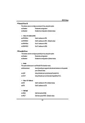
... Disable the configuration. (Default value) Mode This option allows user to 2E8. Enabled Enable the configuration Disabled Disable the configuration.(Default value) BIOS Setup Base I /O Address 378 278 Set IO address to 378. (Default value) Set IO address to 278. Enabled Enable the configuration. Parallel Port This allows users to configure parallel port by using this setting to support bi-directional transfers on the parallel port. (Default value) EPP Using Parallel port as Enhanced Parallel Port. Serial Port B This allows users to configure serial prot B by using...
... Disable the configuration. (Default value) Mode This option allows user to 2E8. Enabled Enable the configuration Disabled Disable the configuration.(Default value) BIOS Setup Base I /O Address 378 278 Set IO address to 378. (Default value) Set IO address to 278. Enabled Enable the configuration. Parallel Port This allows users to configure parallel port by using this setting to support bi-directional transfers on the parallel port. (Default value) EPP Using Parallel port as Enhanced Parallel Port. Serial Port B This allows users to configure serial prot B by using...
User Manual
Page 40
...GA-7BESH-RH Motherboard PS/2 Mouse Set this option 'Enabled' to either PCI or LPC bus. Enabled 'Enabled' forces the PS/2 mouse port to function support for legacy USB. Enabled Enables support for legacy USB (Default Value) Disabled Disables support for legacy USB. USB Controller This item allows users to enable or disable the USB device by setting item to the LPC bus. 40 Legacy USB Support This option allows user to be enabled regardless if a mouse is present. (Default value) Disabled 'Disabled' prevents any installed PS/2 mouse from functioning, but frees up IRQ12. PCI Set...
...GA-7BESH-RH Motherboard PS/2 Mouse Set this option 'Enabled' to either PCI or LPC bus. Enabled 'Enabled' forces the PS/2 mouse port to function support for legacy USB. Enabled Enables support for legacy USB (Default Value) Disabled Disables support for legacy USB. USB Controller This item allows users to enable or disable the USB device by setting item to the LPC bus. 40 Legacy USB Support This option allows user to be enabled regardless if a mouse is present. (Default value) Disabled 'Disabled' prevents any installed PS/2 mouse from functioning, but frees up IRQ12. PCI Set...
User Manual
Page 64
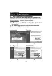
... auto start the installation. 2. Setup completed, click "Finish" to install the drivers. 3. Installation Procedures: 1. Auto Run window Setup Wizard 1.Click "Intel Chipset Software Installation Utility" item. (1) License Aggremment 2.Click "Next". (2) Readme Information 3.Click "Yes". (3) 64 4.Click "Next". (4) If not, please double click the CD-ROM device icon in "My computer", and execute the setup.exe. Intel Chipset Software Installation Utilities Insert the driver CD-title that came with your motherboard into your computer. GA-7BESH...
... auto start the installation. 2. Setup completed, click "Finish" to install the drivers. 3. Installation Procedures: 1. Auto Run window Setup Wizard 1.Click "Intel Chipset Software Installation Utility" item. (1) License Aggremment 2.Click "Next". (2) Readme Information 3.Click "Yes". (3) 64 4.Click "Next". (4) If not, please double click the CD-ROM device icon in "My computer", and execute the setup.exe. Intel Chipset Software Installation Utilities Insert the driver CD-title that came with your motherboard into your computer. GA-7BESH...
User Manual
Page 66
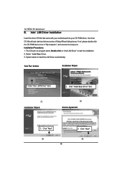
... CD-ROM device icon in "My computer", and execute the setup.exe. The CD auto run program starts, Double click on "Intel LAN Driver" to install the LAN Driver automatically. System starts to start and show a series of Setup Wizard dialog boxes. GA-7BESH-RH Motherboard B. Auto Run window Installation Wizard 1.Click "Intel LAN Driver" item. 2. Click "Next". (4) Installation Procedures: 1. Intel LAN Driver Installation Insert the driver CD-title that came with your motherboard into your CD-ROM driver, the driver...
... CD-ROM device icon in "My computer", and execute the setup.exe. The CD auto run program starts, Double click on "Intel LAN Driver" to install the LAN Driver automatically. System starts to start and show a series of Setup Wizard dialog boxes. GA-7BESH-RH Motherboard B. Auto Run window Installation Wizard 1.Click "Intel LAN Driver" item. 2. Click "Next". (4) Installation Procedures: 1. Intel LAN Driver Installation Insert the driver CD-title that came with your motherboard into your CD-ROM driver, the driver...
User Manual
Page 68
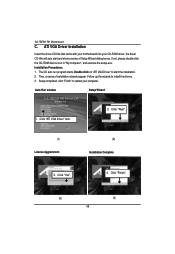
... VGA Driver" item. 2. If not, please double click the CD-ROM device icon in "My computer", and execute the setup.exe. Setup completed, click "Finish" to install the drivers. 3. Click "Finish". (3) (4) 68 The CD auto run program starts, Double click on "ATI VGA Driver" to start and show a series of installation wizards appear. Auto Run window Setup Wizard 1. GA-7BESH-RH Motherboard C. ATI VGA Driver Installation Insert the driver CD-title that came with your motherboard...
... VGA Driver" item. 2. If not, please double click the CD-ROM device icon in "My computer", and execute the setup.exe. Setup completed, click "Finish" to install the drivers. 3. Click "Finish". (3) (4) 68 The CD auto run program starts, Double click on "ATI VGA Driver" to start and show a series of installation wizards appear. Auto Run window Setup Wizard 1. GA-7BESH-RH Motherboard C. ATI VGA Driver Installation Insert the driver CD-title that came with your motherboard...


