User Manual
Page 2
... of Content Item Checklist 4 WARNING 4 Chapter 1 Introduction 5 1.1 Features Summary 5 1.2 GA-7BESH-RH Motherboard Components 8 Chapter 2 Hardware Installation Process 10 2-1: Installing Processor and CPU Haet Sink 10 2-1-1: Installing CPU ...10 2-1-2: Installing Heat Sink 11 2-2: Install memory modules 12 2-3: Connect ...
... of Content Item Checklist 4 WARNING 4 Chapter 1 Introduction 5 1.1 Features Summary 5 1.2 GA-7BESH-RH Motherboard Components 8 Chapter 2 Hardware Installation Process 10 2-1: Installing Processor and CPU Haet Sink 10 2-1-1: Installing CPU ...10 2-1-2: Installing Heat Sink 11 2-2: Install memory modules 12 2-3: Connect ...
User Manual
Page 4
.... 4. Be careful, don't let the screw contact any printed circuit write or parts on the inside. 2. English GA-7BESH-RH Motherboard Item Checklist The GA-7BESH-RH motherboard IDE (ATA100 ) cable x 1 / Floppy cable x 1 CD for motherboard driver & utility GA-7BESH-RH user's manual Serial ATA cable x 4 I/O Shield Kit Power cable x 4 SCSI cable x 1 WARNING! Unplug...little hard to the chassis... In this way you do not become alarmed you can still attach the motherboard to the mounting holes. Sometimes you plug in or remove the ATX power connector on the bag that are separated from the...
.... 4. Be careful, don't let the screw contact any printed circuit write or parts on the inside. 2. English GA-7BESH-RH Motherboard Item Checklist The GA-7BESH-RH motherboard IDE (ATA100 ) cable x 1 / Floppy cable x 1 CD for motherboard driver & utility GA-7BESH-RH user's manual Serial ATA cable x 4 I/O Shield Kit Power cable x 4 SCSI cable x 1 WARNING! Unplug...little hard to the chassis... In this way you do not become alarmed you can still attach the motherboard to the mounting holes. Sometimes you plug in or remove the ATX power connector on the bag that are separated from the...

User Manual
Page 6
English GA-7BESH-RH Motherboard On-Board Peripherals Hardware Monitor On-Board LAN Hardware Monitor BIOS Special Features Additional Features 1 ATA 100 connector 1 Floppyport supports 360K, 720K,1.2M, 1.44M and 2....
English GA-7BESH-RH Motherboard On-Board Peripherals Hardware Monitor On-Board LAN Hardware Monitor BIOS Special Features Additional Features 1 ATA 100 connector 1 Floppyport supports 360K, 720K,1.2M, 1.44M and 2....
User Manual
Page 8
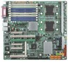
... USB1 Connector 14. Floppy Connector 17. SATA1 Connector 21. SATA4 Connector 24. COM Port 42. CPU 2 FAN 45. FAN R1 (System Rear Fan) 48. English GA-7BESH-RH Motherboard 1.2 GA-7BESH-RH Motherboard Components 1. Primary CPU 2. ITE 8712F-A 7. IPMB1 20. SATA6 Connector 26. Parallel Port 41. CPU 1 FAN 43. SATA3 Connector 23. ZCR 27. FAN 2 (SystemFront Fan) 47...
... USB1 Connector 14. Floppy Connector 17. SATA1 Connector 21. SATA4 Connector 24. COM Port 42. CPU 2 FAN 45. FAN R1 (System Rear Fan) 48. English GA-7BESH-RH Motherboard 1.2 GA-7BESH-RH Motherboard Components 1. Primary CPU 2. ITE 8712F-A 7. IPMB1 20. SATA6 Connector 26. Parallel Port 41. CPU 1 FAN 43. SATA3 Connector 23. ZCR 27. FAN 2 (SystemFront Fan) 47...
User Manual
Page 10
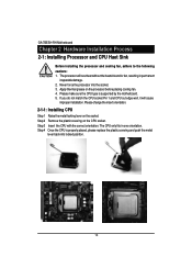
Never force the processor into locked position. 10 Step 3 Insert the CPU with the correct orientation. Step 4 Once the CPU is supported by the motherboard. 5. English GA-7BESH-RH Motherboard Chapter 2 Hardware Installation Process 2-1: Installing Processor and CPU Haet Sink Before installing the processor and cooling fan, adhere to the following cautions: 1. Apply thermal grease ...
Never force the processor into locked position. 10 Step 3 Insert the CPU with the correct orientation. Step 4 Once the CPU is supported by the motherboard. 5. English GA-7BESH-RH Motherboard Chapter 2 Hardware Installation Process 2-1: Installing Processor and CPU Haet Sink Before installing the processor and cooling fan, adhere to the following cautions: 1. Apply thermal grease ...
User Manual
Page 12
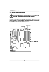
For detail DIMM installation, please refer to the following instructions. English GA-7BESH-RH Motherboard 2-2: Install memory modules Before installing the processor and heatsink, adhere to the following warning: When DIMM LED is ON, do not install/remove DIMM from socket. DIMMC1/C2 DIMMA1/A2 DIMMB1/B2 DIMMD1/D2 12 It supports the 4 FB-DIMM Channels Technology. GA-7BESH-RH has 8 dual inline memory module (DIMM) sokcets. The BIOS will automatically detects memory type and size during system boot.
For detail DIMM installation, please refer to the following instructions. English GA-7BESH-RH Motherboard 2-2: Install memory modules Before installing the processor and heatsink, adhere to the following warning: When DIMM LED is ON, do not install/remove DIMM from socket. DIMMC1/C2 DIMMA1/A2 DIMMB1/B2 DIMMD1/D2 12 It supports the 4 FB-DIMM Channels Technology. GA-7BESH-RH has 8 dual inline memory module (DIMM) sokcets. The BIOS will automatically detects memory type and size during system boot.
User Manual
Page 14
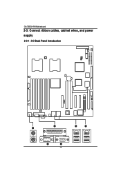
English GA-7BESH-RH Motherboard 2-3: Connect ribbon cables, cabinet wires, and power supply 2-3-1 : I/O Back Panel Introduction 14
English GA-7BESH-RH Motherboard 2-3: Connect ribbon cables, cabinet wires, and power supply 2-3-1 : I/O Back Panel Introduction 14
User Manual
Page 16
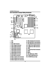
...) 7. SATA 6 (SATA Connector) 11. FAN_R1 (System Fan Connector) 15. F_Panel (Front Panel Connector) 22. JP_REC1 (BIOS Recovery ) 26. FAN_R2 (System Fan Connector) 16. IPMB1 23. GA-7BESH-RH Motherboard 2-3-2 :Connectors & Jumper Setting Introduction English 21 22 20 4 23 11 17 15 14 1 2 16 10 9 8 6 5 12 7 24 26 25 18 19 3 13 1. JP_PASS1(Pasword skip...
...) 7. SATA 6 (SATA Connector) 11. FAN_R1 (System Fan Connector) 15. F_Panel (Front Panel Connector) 22. JP_REC1 (BIOS Recovery ) 26. FAN_R2 (System Fan Connector) 16. IPMB1 23. GA-7BESH-RH Motherboard 2-3-2 :Connectors & Jumper Setting Introduction English 21 22 20 4 23 11 17 15 14 1 2 16 10 9 8 6 5 12 7 24 26 25 18 19 3 13 1. JP_PASS1(Pasword skip...
User Manual
Page 18
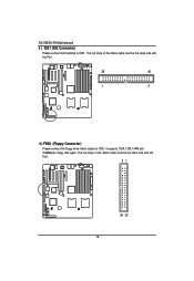
The red stripe of the ribbon cable must be the same side with the Pin1. 21 34 33 18 English GA-7BESH-RH Motherboard 3 ) IDE1 (IDE Connector) Please connect first harddisk to FDD. The red stripe of the ribbon cable must be the same side with the Pin1. 39 40 1 2 4 ) FDD1 (Floppy Connector) Please connect the floppy drive ribbon cables to IDE1. It supports 720K,1.2M,1.44M and 2.88Mbytes floppy disk types.
The red stripe of the ribbon cable must be the same side with the Pin1. 21 34 33 18 English GA-7BESH-RH Motherboard 3 ) IDE1 (IDE Connector) Please connect first harddisk to FDD. The red stripe of the ribbon cable must be the same side with the Pin1. 39 40 1 2 4 ) FDD1 (Floppy Connector) Please connect the floppy drive ribbon cables to IDE1. It supports 720K,1.2M,1.44M and 2.88Mbytes floppy disk types.
User Manual
Page 20
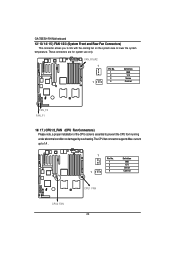
...) Please note, a proper installation of the CPU cooler is essential to 1A . 1 1 Pin No. 1 2 3 4 Definition GND 12V Sense Control CPU2 FAN CPU1 FAN 20 English GA-7BESH-RH Motherboard 12/ 13/ 14/ 15 ) FAN 1/2/3 (System Front and Rear Fan Connectors) This connector allows you to link with the cooling fan on the system case...
...) Please note, a proper installation of the CPU cooler is essential to 1A . 1 1 Pin No. 1 2 3 4 Definition GND 12V Sense Control CPU2 FAN CPU1 FAN 20 English GA-7BESH-RH Motherboard 12/ 13/ 14/ 15 ) FAN 1/2/3 (System Front and Rear Fan Connectors) This connector allows you to link with the cooling fan on the system case...
User Manual
Page 22
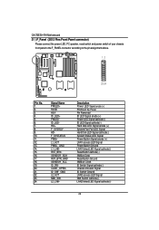
English GA-7BESH-RH Motherboard 21 ) F_Panel (2X12 Pins Front Panel connector) Please connect the power LED, PC speaker, reset switch and power switch of your chassis front panel to ...
English GA-7BESH-RH Motherboard 21 ) F_Panel (2X12 Pins Front Panel connector) Please connect the power LED, PC speaker, reset switch and power switch of your chassis front panel to ...
User Manual
Page 24
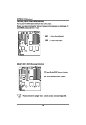
Short: Disable this jumper. To clear CMOS, temporarily short 1-2 pin. 1 1-2 close: Normal (Default) 1 2-3 close: Clear CMOS 25 ) JP_REC1 ( BIOS Recovery Function) Open: Enable BIOS Recovery function. English GA-7BESH-RH Motherboard 24 ) CLR_CMOS1 (Clear CMOS Function) You may clear the CMOS data to prevent from improper use this jumper. Default value doesn't include the "Shunter" to its default values by this function. (Default) Please remove the jumper when system access recovery flopp disk. 24
Short: Disable this jumper. To clear CMOS, temporarily short 1-2 pin. 1 1-2 close: Normal (Default) 1 2-3 close: Clear CMOS 25 ) JP_REC1 ( BIOS Recovery Function) Open: Enable BIOS Recovery function. English GA-7BESH-RH Motherboard 24 ) CLR_CMOS1 (Clear CMOS Function) You may clear the CMOS data to prevent from improper use this jumper. Default value doesn't include the "Shunter" to its default values by this function. (Default) Please remove the jumper when system access recovery flopp disk. 24
User Manual
Page 26
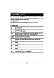
GA-7BESH-RH Motherboard Chapter 3 BIOS Setup BIOS Setup is turned off. The program that it retains the Setup information when the power is an overview of the BIOS ...
GA-7BESH-RH Motherboard Chapter 3 BIOS Setup BIOS Setup is turned off. The program that it retains the Setup information when the power is an overview of the BIOS ...
User Manual
Page 28
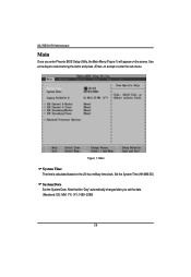
Set the System Time (HH:MM:SS) System Date Set the System Date. Use arrow keys to select among the items and press to accept or enter the sub-menu. Note that the "Day" automatically changed after you enter Phoenix BIOS Setup Utility, the Main Menu (Figure 1) will appear on the 24-hour military time clock. GA-7BESH-RH Motherboard Main Once you set the date. (Weekend: DD: MM: YY) (YY: 1099~2099) 28 Figure 1: Main System Time The time is calculated based on the screen.
Set the System Time (HH:MM:SS) System Date Set the System Date. Use arrow keys to select among the items and press to accept or enter the sub-menu. Note that the "Day" automatically changed after you enter Phoenix BIOS Setup Utility, the Main Menu (Figure 1) will appear on the 24-hour military time clock. GA-7BESH-RH Motherboard Main Once you set the date. (Weekend: DD: MM: YY) (YY: 1099~2099) 28 Figure 1: Main System Time The time is calculated based on the screen.
User Manual
Page 30
... support LBA Mode. ATAPI Removable: Removable disk drive is installed here. Enable this function to set all HDD parameters automatically. Users: Set parameters by User. GA-7BESH-RH Motherboard TYPE 1-39: Predefined types. Auto: Set parameters automatically. (Default Vaules) CD-ROM: Use for ATAPI CD-ROM drives or double click [Auto] to max imize...
... support LBA Mode. ATAPI Removable: Removable disk drive is installed here. Enable this function to set all HDD parameters automatically. Users: Set parameters by User. GA-7BESH-RH Motherboard TYPE 1-39: Predefined types. Auto: Set parameters automatically. (Default Vaules) CD-ROM: Use for ATAPI CD-ROM drives or double click [Auto] to max imize...
User Manual
Page 32
... to run multiple operating systems and applications in a saving of power consumption of processor. Disabled Disables C1 Enhanced Mode. (Default value) No Execute Mode Mem. GA-7BESH-RH Motherboard Intel (R) Virtualization Technology Intel(R) Virtualization Technology will allow a platform to system bus ratio and VID. With virtualization, one computer system can function as multiple "virtual...
... to run multiple operating systems and applications in a saving of power consumption of processor. Disabled Disables C1 Enhanced Mode. (Default value) No Execute Mode Mem. GA-7BESH-RH Motherboard Intel (R) Virtualization Technology Intel(R) Virtualization Technology will allow a platform to system bus ratio and VID. With virtualization, one computer system can function as multiple "virtual...

User Manual
Page 34
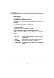
Memory Reset Yes No Select 'Yes', system will set to 'No' automatically. After rebooting system, the Memory Reset item will clear the memory error status. Save the changes and restart system. Disable this function. (Default value) 34 GA-7BESH-RH Motherboard Memory Configuration Figure 2-1: Memory Configuration System Memory/Extended Memory/DIMMGroup 1~8 Status These category is display-only which is determined by POST (Power On Self Test) of the BIOS.
Memory Reset Yes No Select 'Yes', system will set to 'No' automatically. After rebooting system, the Memory Reset item will clear the memory error status. Save the changes and restart system. Disable this function. (Default value) 34 GA-7BESH-RH Motherboard Memory Configuration Figure 2-1: Memory Configuration System Memory/Extended Memory/DIMMGroup 1~8 Status These category is display-only which is determined by POST (Power On Self Test) of the BIOS.
User Manual
Page 36
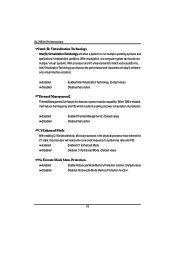
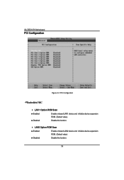
LAN2 Option ROM Scan Enabled Enable onboard LAN2 device and initialize device expansion ROM. (Default value) Disabled Disable this function. GA-7BESH-RH Motherboard PCI Configuration Figure 2-2: PCI Configuration Embedded NIC LAN 1 Option ROM Scan Enabled Enable onboard LAN1 device and initialize device expansion ROM. (Default value) Disabled Disable this function. 36
LAN2 Option ROM Scan Enabled Enable onboard LAN2 device and initialize device expansion ROM. (Default value) Disabled Disable this function. GA-7BESH-RH Motherboard PCI Configuration Figure 2-2: PCI Configuration Embedded NIC LAN 1 Option ROM Scan Enabled Enable onboard LAN1 device and initialize device expansion ROM. (Default value) Disabled Disable this function. 36
User Manual
Page 38
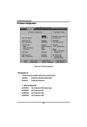
Enabled Enable the configuration (Default value) Disabled Disable the configuration. Base I /O Device Configuration Serial Port A This allows users to 2E8. 38 GA-7BESH-RH Motherboard I/O Device Configuration Figure 2-3: I /O Address/IRQ 3F8/IRQ4 Set IO address to 3F8. (Default value) 2F8/IRQ3 Set IO address to 2F8. 3E8/IRQ4 Set IO address to 3E8. 2E8/IRQ3 Set IO address to configure serial prot A by using this option.
Enabled Enable the configuration (Default value) Disabled Disable the configuration. Base I /O Device Configuration Serial Port A This allows users to 2E8. 38 GA-7BESH-RH Motherboard I/O Device Configuration Figure 2-3: I /O Address/IRQ 3F8/IRQ4 Set IO address to 3F8. (Default value) 2F8/IRQ3 Set IO address to 2F8. 3E8/IRQ4 Set IO address to 3E8. 2E8/IRQ3 Set IO address to configure serial prot A by using this option.
User Manual
Page 40
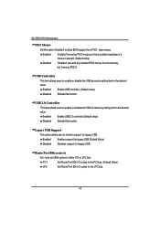
GA-7BESH-RH Motherboard PS/2 Mouse Set this option 'Enabled' to the desired value. USB Controller This item allows users to enable or disable the USB device by setting ...
GA-7BESH-RH Motherboard PS/2 Mouse Set this option 'Enabled' to the desired value. USB Controller This item allows users to enable or disable the USB device by setting ...


