Manual
Page 1
GA-790XTA-UD4 AM3 socket motherboard for AMD Phenom™ II processor/AMD Athlon™ II processor User's Manual Rev. 1001 12ME-790XTA4-1001R
GA-790XTA-UD4 AM3 socket motherboard for AMD Phenom™ II processor/AMD Athlon™ II processor User's Manual Rev. 1001 12ME-790XTA4-1001R
Manual
Page 2
Motherboard GA-790XTA-UD4 Nov. 20, 2009 Motherboard GA-790XTA-UD4 Nov. 20, 2009
Motherboard GA-790XTA-UD4 Nov. 20, 2009 Motherboard GA-790XTA-UD4 Nov. 20, 2009
Manual
Page 3
... made by any form or by GIGABYTE without GIGABYTE's prior written permission. For detailed product information, carefully read or download the information on/from the Support&Downloads\Motherboard\Technology Guide page on your motherboard revision before updating motherboard BIOS, drivers, or when looking ...product-related information, check on our website at: http://www.gigabyte.com.tw Identifying Your Motherboard Revision The revision number on our website. For example, "REV: 1.0" means the revision of the motherboard is the property of this manual is protected by copyright laws...
... made by any form or by GIGABYTE without GIGABYTE's prior written permission. For detailed product information, carefully read or download the information on/from the Support&Downloads\Motherboard\Technology Guide page on your motherboard revision before updating motherboard BIOS, drivers, or when looking ...product-related information, check on our website at: http://www.gigabyte.com.tw Identifying Your Motherboard Revision The revision number on our website. For example, "REV: 1.0" means the revision of the motherboard is the property of this manual is protected by copyright laws...
Manual
Page 4
Table of Contents Box Contents...6 Optional Items...6 GA-790XTA-UD4 Motherboard Layout 7 Block Diagram...8 Chapter 1 Hardware Installation 9 1-1 Installation Precautions 9 1-2 Product Specifications 10 1-3 Installing the CPU and CPU Cooler 13 1-3-1 Installing the CPU 13 1-3-2 Installing the CPU ...
Table of Contents Box Contents...6 Optional Items...6 GA-790XTA-UD4 Motherboard Layout 7 Block Diagram...8 Chapter 1 Hardware Installation 9 1-1 Installation Precautions 9 1-2 Product Specifications 10 1-3 Installing the CPU and CPU Cooler 13 1-3-1 Installing the CPU 13 1-3-2 Installing the CPU ...
Manual
Page 6
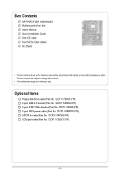
The box contents are for reference only. Box Contents GA-790XTA-UD4 motherboard Motherboard driver disk User's Manual Quick Installation Guide One IDE cable Four SATA 3Gb/s cables I/O Shield • The box contents above are subject to change without notice. • The motherboard image is for reference only and the actual items shall depend on the product...
The box contents are for reference only. Box Contents GA-790XTA-UD4 motherboard Motherboard driver disk User's Manual Quick Installation Guide One IDE cable Four SATA 3Gb/s cables I/O Shield • The box contents above are subject to change without notice. • The motherboard image is for reference only and the actual items shall depend on the product...
Manual
Page 7
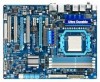
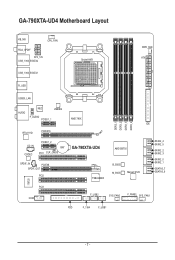
GA-790XTA-UD4 Motherboard Layout KB_MS CPU_FAN RCA_SPDIF ATX_12V USB_1394_ESATA2 USB_1394_ESATA1 Socket AM3 PWR_FAN ATX R_USB USB30_LAN AUDIO NEC JMB362 F_AUDIO PCIEX1_1 AMD 790X IDE RTL8111D PCIEX16 IT8720 DDR3_1 DDR3_2 DDR3_3 DDR3_4 CD_IN CODEC PCIEX1_2 BAT PCI1 CLR_CMOS GA-790XTA-UD4 SPDIF_IN PCIEX8 SPDIF_OUT PCI2 TSB43AB23 AMD SB750 B_BIOS M_BIOS Marvell 9128 SATA2_4 SATA2_5 SATA2_2 SATA2_3 SATA2_0 SATA2_1 GSATA3_7 GSATA3_6 PCI3 COM F_USB2 SYS_FAN2 F_PANEL SYS_FAN1 FDD F_1394 F_USB1 - 7 -
GA-790XTA-UD4 Motherboard Layout KB_MS CPU_FAN RCA_SPDIF ATX_12V USB_1394_ESATA2 USB_1394_ESATA1 Socket AM3 PWR_FAN ATX R_USB USB30_LAN AUDIO NEC JMB362 F_AUDIO PCIEX1_1 AMD 790X IDE RTL8111D PCIEX16 IT8720 DDR3_1 DDR3_2 DDR3_3 DDR3_4 CD_IN CODEC PCIEX1_2 BAT PCI1 CLR_CMOS GA-790XTA-UD4 SPDIF_IN PCIEX8 SPDIF_OUT PCI2 TSB43AB23 AMD SB750 B_BIOS M_BIOS Marvell 9128 SATA2_4 SATA2_5 SATA2_2 SATA2_3 SATA2_0 SATA2_1 GSATA3_7 GSATA3_6 PCI3 COM F_USB2 SYS_FAN2 F_PANEL SYS_FAN1 FDD F_1394 F_USB1 - 7 -
Manual
Page 9
... the AC power by your hands dry and first touch a metal object to eliminate static electricity. • Prior to installing the motherboard, please have a problem related to wear an electrostatic discharge (ESD) wrist strap when handling electronic com- Prior to installation, carefully ... an electrostatic shielding container. • Before unplugging the power supply cable from the power outlet before installing or removing the motherboard or other hardware components. • When connecting hardware components to the internal connectors on the computer power during the installation...
... the AC power by your hands dry and first touch a metal object to eliminate static electricity. • Prior to installing the motherboard, please have a problem related to wear an electrostatic discharge (ESD) wrist strap when handling electronic com- Prior to installation, carefully ... an electrostatic shielding container. • Before unplugging the power supply cable from the power outlet before installing or removing the motherboard or other hardware components. • When connecting hardware components to the internal connectors on the computer power during the installation...
Manual
Page 12
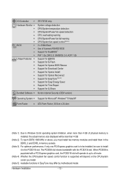
... memory size displayed will be less than 4 GB of physical memory is supported will operate at up to install it in EasyTune may differ by motherboard model. I/O Controller w Hardware Monitor w w w w w w BIOS w w w w Unique Features w w w w w w w w w w Bundled Software w iTE IT8720 chip System voltage detection CPU/System temperature detection CPU/System/Power fan speed detection...
... memory size displayed will be less than 4 GB of physical memory is supported will operate at up to install it in EasyTune may differ by motherboard model. I/O Controller w Hardware Monitor w w w w w w BIOS w w w w Unique Features w w w w w w w w w w Bundled Software w iTE IT8720 chip System voltage detection CPU/System temperature detection CPU/System/Power fan speed detection...
Manual
Page 13
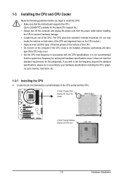
... to your hardware specifications including the CPU, graphics card, memory, hard drive, etc. 1-3-1 Installing the CPU A. It is not recommended that the motherboard supports the CPU. (Go to GIGABYTE's website for the peripherals. If you begin to install the CPU: • Make sure that the system bus frequency be inserted if oriented...
... to your hardware specifications including the CPU, graphics card, memory, hard drive, etc. 1-3-1 Installing the CPU A. It is not recommended that the motherboard supports the CPU. (Go to GIGABYTE's website for the peripherals. If you begin to install the CPU: • Make sure that the system bus frequency be inserted if oriented...
Manual
Page 14
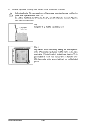
... insert the CPU into the CPU socket. Adjust the CPU orientation if this occurs. Follow the steps below to correctly install the CPU into the motherboard CPU socket. • Before installing the CPU, make sure to turn off the computer and unplug the power cord from the power outlet to prevent...
... insert the CPU into the CPU socket. Adjust the CPU orientation if this occurs. Follow the steps below to correctly install the CPU into the motherboard CPU socket. • Before installing the CPU, make sure to turn off the computer and unplug the power cord from the power outlet to prevent...
Manual
Page 15
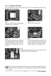
...an even and thin layer of thermal grease on the surface of the CPU cooler to the CPU fan header (CPU_FAN) on the motherboard. Hardware Installation 1-3-2 Installing the CPU Cooler Follow the steps below to correctly install the CPU cooler on the CPU. (The following procedure uses... the GIGABYTE cooler as the picture above shows) to lock into place. (Refer to your CPU cooler installation manual for instructions on installing the cooler...
...an even and thin layer of thermal grease on the surface of the CPU cooler to the CPU fan header (CPU_FAN) on the motherboard. Hardware Installation 1-3-2 Installing the CPU Cooler Follow the steps below to correctly install the CPU cooler on the CPU. (The following procedure uses... the GIGABYTE cooler as the picture above shows) to lock into place. (Refer to your CPU cooler installation manual for instructions on installing the cooler...
Manual
Page 16
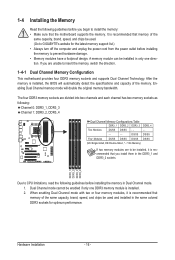
... to install the memory: • Make sure that memory of the same capacity, brand, speed, and chips be used. (Go to GIGABYTE's website for optimum performance. The four DDR3 memory sockets are unable to be installed in Dual Channel mode. 1. Dual Channel mode cannot be...Double-Sided, "- -"=No Memory) If two memory modules are to insert the memory, switch the direction. 1-4-1 Dual Channel Memory Configuration This motherboard provides four DDR3 memory sockets and supports Dual Channel Technology. After the memory is recommended that you install them in the same colored DDR3 sockets...
... to install the memory: • Make sure that memory of the same capacity, brand, speed, and chips be used. (Go to GIGABYTE's website for optimum performance. The four DDR3 memory sockets are unable to be installed in Dual Channel mode. 1. Dual Channel mode cannot be...Double-Sided, "- -"=No Memory) If two memory modules are to insert the memory, switch the direction. 1-4-1 Dual Channel Memory Configuration This motherboard provides four DDR3 memory sockets and supports Dual Channel Technology. After the memory is recommended that you install them in the same colored DDR3 sockets...
Manual
Page 17
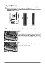
..., make sure to turn off the computer and unplug the power cord from the power outlet to prevent damage to install DDR3 DIMMs on this motherboard.
..., make sure to turn off the computer and unplug the power cord from the power outlet to prevent damage to install DDR3 DIMMs on this motherboard.
Manual
Page 18
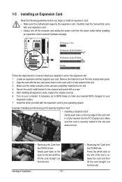
... the card and then lift the card straight out from the power outlet before you begin to install an expansion card: • Make sure the motherboard supports the expansion card. Make sure the card is fully seated in your expansion card(s). 7. Align the card with your card. Hardware Installation - 18 - •...
... the card and then lift the card straight out from the power outlet before you begin to install an expansion card: • Make sure the motherboard supports the expansion card. Make sure the card is fully seated in your expansion card(s). 7. Align the card with your card. Hardware Installation - 18 - •...
Manual
Page 19
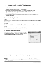
... needed or not depending on top of identical brand and chip and correct driver - 1-6 Setup of your graphics cards for the power requirement) B. A CrossFireX-supported motherboard with your graphics cards for more information about enabling CrossFireX technology. - 19 - Windows 7, Windows Vista, or Windows XP operating system - System Requirements - Refer to the...
... needed or not depending on top of identical brand and chip and correct driver - 1-6 Setup of your graphics cards for the power requirement) B. A CrossFireX-supported motherboard with your graphics cards for more information about enabling CrossFireX technology. - 19 - Windows 7, Windows Vista, or Windows XP operating system - System Requirements - Refer to the...
Manual
Page 20
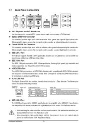
...-45 LAN Port The Gigabit Ethernet LAN port provides Internet connection at up to connect a PS/2 keyboard. Do not rock it straight out from the motherboard. • When removing the cable, pull it side to side to a back panel connector, first remove the cable from your device and then remove it...
...-45 LAN Port The Gigabit Ethernet LAN port provides Internet connection at up to connect a PS/2 keyboard. Do not rock it straight out from the motherboard. • When removing the cable, pull it side to side to a back panel connector, first remove the cable from your device and then remove it...
Manual
Page 22
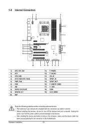
... devices and your devices are compliant with the connectors you wish to connect. • Before installing the devices, be sure to the connector on the motherboard. 1-8 Internal Connectors 13 5 2 7 12 10 13 8 19 14 15 9 18 1) ATX_12V_2X4 2) ATX 3) CPU_FAN 4) SYS_FAN1/SYS_FAN2 5) PWR_FAN 6) FDD 7) IDE 8) SATA2_0/1/2/3/4/5 9) GSATA3_6/7 10) BAT 6 17 16 4 11...
... devices and your devices are compliant with the connectors you wish to connect. • Before installing the devices, be sure to the connector on the motherboard. 1-8 Internal Connectors 13 5 2 7 12 10 13 8 19 14 15 9 18 1) ATX_12V_2X4 2) ATX 3) CPU_FAN 4) SYS_FAN1/SYS_FAN2 5) PWR_FAN 6) FDD 7) IDE 8) SATA2_0/1/2/3/4/5 9) GSATA3_6/7 10) BAT 6 17 16 4 11...
Manual
Page 23
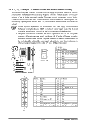
If a power supply is turned off and all the components on the motherboard. 1/2) ATX_12V_2X4/ATX (2x4 12V Power Connector and 2x12 Main Power Connector) With the use of the power connector, the power supply can lead to an ... a power supply providing a 2x4 12V and a 2x12 power connector, remove the protective covers from the 12V power connector and the main power connector on the motherboard. If the 12V power connector is not connected, the computer will not start. • To meet expansion requirements, it is recommended that a power supply that...
If a power supply is turned off and all the components on the motherboard. 1/2) ATX_12V_2X4/ATX (2x4 12V Power Connector and 2x12 Main Power Connector) With the use of the power connector, the power supply can lead to an ... a power supply providing a 2x4 12V and a 2x12 power connector, remove the protective covers from the 12V power connector and the main power connector on the motherboard. If the 12V power connector is not connected, the computer will not start. • To meet expansion requirements, it is recommended that a power supply that...
Manual
Page 24
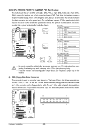
... CPU or the system may result in the correct orientation (the black connector wire is typically designated by a stripe of different color. The motherboard supports CPU fan speed control, which requires the use of the connector and the floppy disk drive cable. CPU_FAN: Pin No. Definition 1 GND...fan be sure to locate pin 1 of a CPU fan with fan speed control design. 3/4/5) CPU_FAN/SYS_FAN1/SYS_FAN2/PWR_FAN (Fan Headers) The motherboard has a 4-pin CPU fan header (CPU_FAN), a 3-pin (SYS_FAN2) and a 4-pin (SYS_ FAN1) system fan headers, and a 3-pin power fan header ...
... CPU or the system may result in the correct orientation (the black connector wire is typically designated by a stripe of different color. The motherboard supports CPU fan speed control, which requires the use of the connector and the floppy disk drive cable. CPU_FAN: Pin No. Definition 1 GND...fan be sure to locate pin 1 of a CPU fan with fan speed control design. 3/4/5) CPU_FAN/SYS_FAN1/SYS_FAN2/PWR_FAN (Fan Headers) The motherboard has a 4-pin CPU fan header (CPU_FAN), a 3-pin (SYS_FAN2) and a 4-pin (SYS_ FAN1) system fan headers, and a 3-pin power fan header ...
Manual
Page 28
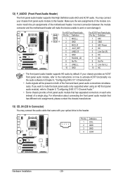
... (only supported when using an HD front panel audio module), refer to work or even damage it. Incorrect connection between the module connector and the motherboard header will be present on how to this header. Definition 1 MIC2_L 1 MIC 9 10 2 GND 2 GND 3 MIC2_R 3 MIC Power 4 -ACZ_DET 4 NC 5 LINE2_R 5 Line Out...header supports HD audio by default. If your chassis provides an AC'97 front panel audio module, refer to the instructions on both of the motherboard header. Pin No. For HD Front Panel Audio: For AC'97 Front Panel Audio: 1 2 Pin No. 12) F_AUDIO (Front Panel Audio...
... (only supported when using an HD front panel audio module), refer to work or even damage it. Incorrect connection between the module connector and the motherboard header will be present on how to this header. Definition 1 MIC2_L 1 MIC 9 10 2 GND 2 GND 3 MIC2_R 3 MIC Power 4 -ACZ_DET 4 NC 5 LINE2_R 5 Line Out...header supports HD audio by default. If your chassis provides an AC'97 front panel audio module, refer to the instructions on both of the motherboard header. Pin No. For HD Front Panel Audio: For AC'97 Front Panel Audio: 1 2 Pin No. 12) F_AUDIO (Front Panel Audio...


