Manual
Page 4
Table of Contents Box Contents...6 Optional Items...6 GA-790XTA-UD4 Motherboard Layout 7 Block Diagram...8 Chapter 1 Hardware Installation 9 1-1 Installation Precautions 9 1-2 Product Specifications 10 1-3 Installing the CPU and CPU Cooler 13 1-3-1 Installing the CPU 13 1-3-2 Installing the CPU Cooler 15 1-4 Installing the Memory 16 1-4-1 Dual Channel Memory Configuration 16 1-4-2 Installing a Memory 17 1-5 Installing an Expansion Card 18 1-6 Setup of...
Table of Contents Box Contents...6 Optional Items...6 GA-790XTA-UD4 Motherboard Layout 7 Block Diagram...8 Chapter 1 Hardware Installation 9 1-1 Installation Precautions 9 1-2 Product Specifications 10 1-3 Installing the CPU and CPU Cooler 13 1-3-1 Installing the CPU 13 1-3-2 Installing the CPU Cooler 15 1-4 Installing the Memory 16 1-4-1 Dual Channel Memory Configuration 16 1-4-2 Installing a Memory 17 1-5 Installing an Expansion Card 18 1-6 Setup of...
Manual
Page 8
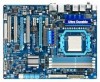
.... The PCIEX8 slot shares bandwidth with a PCI Express graphics card, the PCIEX16 slot will operate at up to install it in the DDR3_3 and DDR3_4 memory sockets. - 8 - Block Diagram 2 PCI Express x8 (Note 1) 1 PCI Express x16 (Note 1) PCIe CLK or (100 MHz) AM3 CPU CPU CLK+/- (200 MHz) DDR3 1866 ...(O.C.) (Note 2)/ 1333/1066 MHz Dual Channel Memory Hyper Transport 3.0 Switch PCI Express Bus x16 x1 x1 x1 PCIe CLK (100 MHz) 2 PCI Express x1 RTL8111D RJ45 LAN 6 SATA 3Gb/s ATA-133/100...
.... The PCIEX8 slot shares bandwidth with a PCI Express graphics card, the PCIEX16 slot will operate at up to install it in the DDR3_3 and DDR3_4 memory sockets. - 8 - Block Diagram 2 PCI Express x8 (Note 1) 1 PCI Express x16 (Note 1) PCIe CLK or (100 MHz) AM3 CPU CPU CLK+/- (200 MHz) DDR3 1866 ...(O.C.) (Note 2)/ 1333/1066 MHz Dual Channel Memory Hyper Transport 3.0 Switch PCI Express Bus x16 x1 x1 x1 PCIe CLK (100 MHz) 2 PCI Express x1 RTL8111D RJ45 LAN 6 SATA 3Gb/s ATA-133/100...
Manual
Page 9
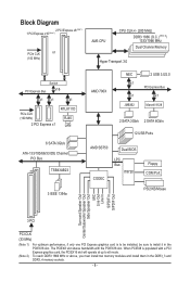
... components. • When connecting hardware components to the internal connectors on the computer power during the installation process can become damaged as a motherboard, CPU or memory. If you are connected tightly and securely. • When handling the motherboard, avoid touching any installation steps or have an ESD wrist strap, keep your...
... components. • When connecting hardware components to the internal connectors on the computer power during the installation process can become damaged as a motherboard, CPU or memory. If you are connected tightly and securely. • When handling the motherboard, avoid touching any installation steps or have an ESD wrist strap, keep your...
Manual
Page 10
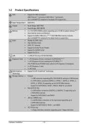
...AM3 processors: AMD Phenom™ II processor/ AMD Athlon™ II processor/ (Go to GIGABYTE's website for the latest CPU support list.) Hyper Transport Bus 5200 MT/s Chipset Memory Audio North Bridge: AMD 790X South Bridge: AMD SB750 4... x 1.5V DDR3 DIMM sockets supporting up to 16 GB of system memory (Note 1) Dual channel memory architecture Support for DDR3 1866 (O.C.) (Note 2)/1333/1066 MHz memory modules (Go to GIGABYTE's website for the latest memory support list.) Realtek ALC889 codec High Definition Audio ...
...AM3 processors: AMD Phenom™ II processor/ AMD Athlon™ II processor/ (Go to GIGABYTE's website for the latest CPU support list.) Hyper Transport Bus 5200 MT/s Chipset Memory Audio North Bridge: AMD 790X South Bridge: AMD SB750 4... x 1.5V DDR3 DIMM sockets supporting up to 16 GB of system memory (Note 1) Dual channel memory architecture Support for DDR3 1866 (O.C.) (Note 2)/1333/1066 MHz memory modules (Go to GIGABYTE's website for the latest memory support list.) Realtek ALC889 codec High Definition Audio ...
Manual
Page 12
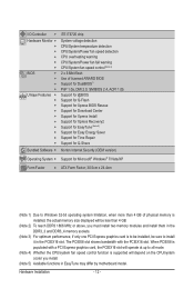
...ATX Form Factor; 30.5cm x 24.4cm (Note 1) Due to Windows 32-bit operating system limitation, when more than 4 GB of physical memory is installed, the actual memory size displayed will be sure to x8 mode. (Note 4) Whether the CPU/system fan speed control function is supported will operate at up... bandwidth with a PCI Express graphics card, the PCIEX16 slot will depend on the CPU/system cooler you must install two memory modules and install them in the DDR3_3 and DDR3_4 memory sockets. (Note 3) For optimum performance, if only one PCI Express graphics card is to be installed, be less than...
...ATX Form Factor; 30.5cm x 24.4cm (Note 1) Due to Windows 32-bit operating system limitation, when more than 4 GB of physical memory is installed, the actual memory size displayed will be sure to x8 mode. (Note 4) Whether the CPU/system fan speed control function is supported will operate at up... bandwidth with a PCI Express graphics card, the PCIEX16 slot will depend on the CPU/system cooler you must install two memory modules and install them in the DDR3_3 and DDR3_4 memory sockets. (Note 3) For optimum performance, if only one PCI Express graphics card is to be installed, be less than...
Manual
Page 13
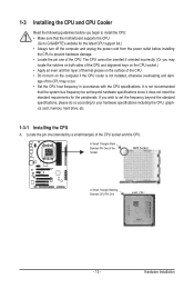
If you begin to install the CPU: • Make sure that the motherboard supports the CPU. (Go to GIGABYTE's website for the peripherals. age of the CPU may locate the notches on both sides of the CPU and alignment keys on the CPU socket.) &#... the power outlet before you wish to set beyond the standard specifications, please do so according to your hardware specifications including the CPU, graphics card, memory, hard drive, etc. 1-3-1 Installing the CPU A. Locate the pin one of the CPU. A Small Triangle Mark Denotes Pin One of the Socket AM3 Socket A Small...
If you begin to install the CPU: • Make sure that the motherboard supports the CPU. (Go to GIGABYTE's website for the peripherals. age of the CPU may locate the notches on both sides of the CPU and alignment keys on the CPU socket.) &#... the power outlet before you wish to set beyond the standard specifications, please do so according to your hardware specifications including the CPU, graphics card, memory, hard drive, etc. 1-3-1 Installing the CPU A. Locate the pin one of the CPU. A Small Triangle Mark Denotes Pin One of the Socket AM3 Socket A Small...
Manual
Page 16
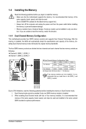
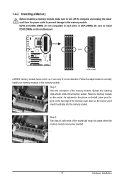
... DS=Double-Sided, "- -"=No Memory) If two memory modules are to be installed, it is installed. 2. After the memory is recommended that memory of the same capacity, brand, speed, and chips be used . (Go to GIGABYTE's website for optimum performance. A memory module can be installed in the ...same colored DDR3 sockets for the latest memory support list.) • Always ...
... DS=Double-Sided, "- -"=No Memory) If two memory modules are to be installed, it is installed. 2. After the memory is recommended that memory of the same capacity, brand, speed, and chips be used . (Go to GIGABYTE's website for optimum performance. A memory module can be installed in the ...same colored DDR3 sockets for the latest memory support list.) • Always ...
Manual
Page 17
...install your fingers on the top edge of the socket will snap into the memory socket. Spread the retaining clips at both ends of the memory module. Step 1: Note the orientation of the memory socket. DDR3 and DDR2 DIMMs are not compatible to each other or DDR... the left, place your memory modules in one direction. Notch DDR3 DIMM A DDR3 memory module has a notch, so it vertically into place when the memory module is securely inserted. - 17 - Hardware Installation Place the memory module on the socket. 1-4-2 Installing a Memory Before installing a memory module, make sure to ...
...install your fingers on the top edge of the socket will snap into the memory socket. Spread the retaining clips at both ends of the memory module. Step 1: Note the orientation of the memory socket. DDR3 and DDR2 DIMMs are not compatible to each other or DDR... the left, place your memory modules in one direction. Notch DDR3 DIMM A DDR3 memory module has a notch, so it vertically into place when the memory module is securely inserted. - 17 - Hardware Installation Place the memory module on the socket. 1-4-2 Installing a Memory Before installing a memory module, make sure to ...
Manual
Page 36
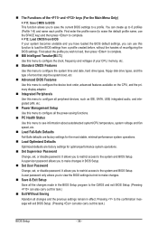
..., you wish to load, then press to complete. MB Intelligent Tweaker(M.I.T.) Use this menu to configure the clock, frequency and voltages of your CPU, memory, etc. Standard CMOS Features Use this menu to configure the system time and date, hard drive types, floppy disk drive types, and the type...
..., you wish to load, then press to complete. MB Intelligent Tweaker(M.I.T.) Use this menu to configure the clock, frequency and voltages of your CPU, memory, etc. Standard CMOS Features Use this menu to configure the system time and date, hard drive types, floppy disk drive types, and the type...

Manual
Page 37
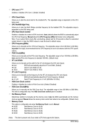
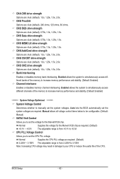
... system instability or other unexpected results. (Inadequately altering the settings may result in system's failure to CPU, chipset, or memory and reduce the useful life of these components. CPU Host Clock Control x CPU Frequency(MHz) PCIE Clock(MHz) HT... Link Width HT Link Frequency Set Memory Clock x Memory Clock } DRAM Configuration ******** System Voltage Optimized ******** System Voltage Control x SATA3 Volt Control x CPU PLL Voltage Control x DRAM Voltage...
... system instability or other unexpected results. (Inadequately altering the settings may result in system's failure to CPU, chipset, or memory and reduce the useful life of these components. CPU Host Clock Control x CPU Frequency(MHz) PCIE Clock(MHz) HT... Link Width HT Link Frequency Set Memory Clock x Memory Clock } DRAM Configuration ******** System Voltage Optimized ******** System Voltage Control x SATA3 Volt Control x CPU PLL Voltage Control x DRAM Voltage...
Manual
Page 39
... Link Width to 8 bit. 16 bit Sets HT Link Width to X4.00. Auto lets BIOS automatically set the VGA Core clock. X8.00 Sets Memory Clock to x1~x10 (200 MHz~2.0 GHz). PCIE Clock(MHz) Allows you to X5.33. VGA Core Clock control Enables or disables the control of... host clock. This item is configurable only if the VGA Core Clock control option is highly recommended that supports this feature. - 39 - X5.33 Sets Memory Clock to manually set in accordance with the CPU specifications. BIOS Setup The adjustable range is present only if you install a CPU that the CPU...
... Link Width to 8 bit. 16 bit Sets HT Link Width to X4.00. Auto lets BIOS automatically set the VGA Core clock. X8.00 Sets Memory Clock to x1~x10 (200 MHz~2.0 GHz). PCIE Clock(MHz) Allows you to X5.33. VGA Core Clock control Enables or disables the control of... host clock. This item is configurable only if the VGA Core Clock control option is highly recommended that supports this feature. - 39 - X5.33 Sets Memory Clock to manually set in accordance with the CPU specifications. BIOS Setup The adjustable range is present only if you install a CPU that the CPU...
Manual
Page 40
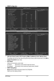
... Allows you to single dual-channel. Options are synchronous to be configurable. Ganged Sets memory control mode to set memory control mode. BIOS Setup - 40 - Unganged Sets memory control mode to two single-channel. (Default) DDR3 Timing Items Manual allows all DDR3...), Manual. DRAM Configuration CMOS Setup Utility-Copyright (C) 1984-2009 Award Software DRAM Configuration CPU Host Clock Control x CPU Frequency(MHz) Set Memory Clock x Memory Clock DCTs Mode DDR3 Timing Items x CAS# latency x RAS to CAS R/W Delay x Row Precharge Time x Minimum RAS Active Time ...
... Allows you to single dual-channel. Options are synchronous to be configurable. Ganged Sets memory control mode to set memory control mode. BIOS Setup - 40 - Unganged Sets memory control mode to two single-channel. (Default) DDR3 Timing Items Manual allows all DDR3...), Manual. DRAM Configuration CMOS Setup Utility-Copyright (C) 1984-2009 Award Software DRAM Configuration CPU Host Clock Control x CPU Frequency(MHz) Set Memory Clock x Memory Clock DCTs Mode DDR3 Timing Items x CAS# latency x RAS to CAS R/W Delay x Row Precharge Time x Minimum RAS Active Time ...
Manual
Page 42
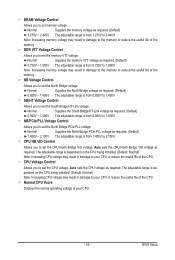
...Supplies the CPU PLL voltage as required. Note: Increasing CPU voltage may result in damage to increase memory performance and stability. (Default: Enabled) Channel interleave Enables or disables memory channel interleaving. CHA CKE drive strength Options are : Auto (default), 1.0x, 1.25x, 1.5x...2.0x. CHB CS/ODT drive strength Options are : Auto (default), 0.75x, 1.0x, 1.25x, 1.5x. Bank Interleaving Enables or disables memory bank interleaving. Manual allows all voltage control items below to be configurable. (Default: Manual) SATA3 Volt Control Allows you to set the system ...
...Supplies the CPU PLL voltage as required. Note: Increasing CPU voltage may result in damage to increase memory performance and stability. (Default: Enabled) Channel interleave Enables or disables memory channel interleaving. CHA CKE drive strength Options are : Auto (default), 1.0x, 1.25x, 1.5x...2.0x. CHB CS/ODT drive strength Options are : Auto (default), 0.75x, 1.0x, 1.25x, 1.5x. Bank Interleaving Enables or disables memory bank interleaving. Manual allows all voltage control items below to be configurable. (Default: Manual) SATA3 Volt Control Allows you to set the system ...
Manual
Page 43
... to 1.400V. NB/PCIe/PLL Voltage Control Allows you to set the North Bridge voltage. CPU NB VID Control Allows you to set memory voltage. Auto sets the CPU voltage as required. (Default) 0.940V ~ 1.500V The adjustable range is from 0.720V to 1.050V. Normal... Supplies the North Bridge voltage as required. (Default) 1.275V ~ 2.445V The adjustable range is from 0.940V to 1.500V. Normal Supplies the memory voltage as required. (Default) 0.920V ~ 1.400V The adjustable range is dependent on the CPU being installed. (Default: Normal) Note: Increasing CPU voltage...
... to 1.400V. NB/PCIe/PLL Voltage Control Allows you to set the North Bridge voltage. CPU NB VID Control Allows you to set memory voltage. Auto sets the CPU voltage as required. (Default) 0.940V ~ 1.500V The adjustable range is from 0.720V to 1.050V. Normal... Supplies the North Bridge voltage as required. (Default) 1.275V ~ 2.445V The adjustable range is from 0.940V to 1.500V. Normal Supplies the memory voltage as required. (Default) 0.920V ~ 1.400V The adjustable range is dependent on the CPU being installed. (Default: Normal) Note: Increasing CPU voltage...
Manual
Page 44
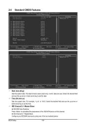
...: Save F6: Fail-Safe Defaults ESC: Exit F1: General Help F7: Optimized Defaults CMOS Setup Utility-Copyright (C) 1984-2009 Award Software Standard CMOS Features Base Memory Extended Memory 640K 2046M Item Help Menu Level Move Enter: Select F5: Previous Values +/-/PU/PD: Value F10: Save F6: Fail-Safe Defaults ESC: Exit...
...: Save F6: Fail-Safe Defaults ESC: Exit F1: General Help F7: Optimized Defaults CMOS Setup Utility-Copyright (C) 1984-2009 Award Software Standard CMOS Features Base Memory Extended Memory 640K 2046M Item Help Menu Level Move Enter: Select F5: Previous Values +/-/PU/PD: Value F10: Save F6: Fail-Safe Defaults ESC: Exit...
Manual
Page 45
... for all other errors. (Default) All, But Diskette The system boot will be reserved for faster system startup. Cylinder Number of extended memory. - 45 - Landing Zone Landing zone. Options are : Auto (default), Large. Options are : Auto (default), CHS, LBA, Large.... No Errors The system boot will stop for all other errors. Base Memory Also called conventional memory. Extended Memory The amount of cylinders. Capacity Approximate capacity of heads. The following fields display your IDE/SATA devices by the BIOS ...
... for all other errors. (Default) All, But Diskette The system boot will be reserved for faster system startup. Cylinder Number of extended memory. - 45 - Landing Zone Landing zone. Options are : Auto (default), Large. Options are : Auto (default), CHS, LBA, Large.... No Errors The system boot will stop for all other errors. Base Memory Also called conventional memory. Extended Memory The amount of cylinders. Capacity Approximate capacity of heads. The following fields display your IDE/SATA devices by the BIOS ...
Manual
Page 53
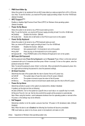
... system. (Default: Enabled) Power On By Mouse Allows the system to be turned on Windows Vista operating system only. - 53 - Note: When using this item. Memory The system returns to its last known awake state upon the return of Month): Turn on the system at least 1A on by a PS/2 keyboard...
... system. (Default: Enabled) Power On By Mouse Allows the system to be turned on Windows Vista operating system only. - 53 - Note: When using this item. Memory The system returns to its last known awake state upon the return of Month): Turn on the system at least 1A on by a PS/2 keyboard...
Manual
Page 63
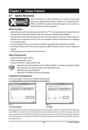
.... actual size requirements vary, depending on the first SATA connector is the first physical drive. - 63 - A. System Requirements: • At least 512 MB of system memory • VESA compatible graphics card • Windows XP with Xpress Recovery cannot be restored using Xpress Recovery2. • USB hard drives are not supported. •...
.... actual size requirements vary, depending on the first SATA connector is the first physical drive. - 63 - A. System Requirements: • At least 512 MB of system memory • VESA compatible graphics card • Windows XP with Xpress Recovery cannot be restored using Xpress Recovery2. • USB hard drives are not supported. •...
Manual
Page 70
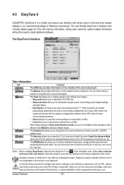
4-3 EasyTune 6 GIGABYTE's EasyTune 6 is a simple and easy-to-use interface that allows users to fine-tune their system-related information without the need to see its information. The user-friendly EasyTune 6 interface also includes tabbed pages for CPU and memory information, letting users...Available functions in the notification area. The EasyTune 6 Interface Tabs Information Tab Function The CPU tab provides information on the installed memory module(s). The Tuner tab allows you to monitor hardware temperature, voltage and fan speed and set . The Graphics tab allows you...
4-3 EasyTune 6 GIGABYTE's EasyTune 6 is a simple and easy-to-use interface that allows users to fine-tune their system-related information without the need to see its information. The user-friendly EasyTune 6 interface also includes tabbed pages for CPU and memory information, letting users...Available functions in the notification area. The EasyTune 6 Interface Tabs Information Tab Function The CPU tab provides information on the installed memory module(s). The Tuner tab allows you to monitor hardware temperature, voltage and fan speed and set . The Graphics tab allows you...
Manual
Page 77
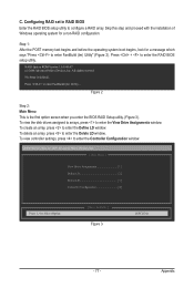
... the first option screen when you enter the BIOS RAID Setup utility. (Figure 3). Figure 2 Step 2: Main Menu This is defined.. Appendix Step 1: After the POST memory test begins and before the operating system boot begins, look for a non-RAID configuration. To view controller settings, press to enter FastBuild (tm) Utility" (Figure...
... the first option screen when you enter the BIOS RAID Setup utility. (Figure 3). Figure 2 Step 2: Main Menu This is defined.. Appendix Step 1: After the POST memory test begins and before the operating system boot begins, look for a non-RAID configuration. To view controller settings, press to enter FastBuild (tm) Utility" (Figure...


