Manual
Page 1
GA-6KIEH-RH GA-6KIEH2-RH GA-6KIEL-RH Intel® mini-ITX Motherboard USER'S MANUAL Intel® mini-ITX Motherboard Rev. 1201 * The WEEE marking on the product indicates this product must not be disposed of with user's other household waste and must be handed over to a designated collection point for the recycling of waste electrical and electronic equipment!! * The WEEE marking applies only in European Union's member states.
GA-6KIEH-RH GA-6KIEH2-RH GA-6KIEL-RH Intel® mini-ITX Motherboard USER'S MANUAL Intel® mini-ITX Motherboard Rev. 1201 * The WEEE marking on the product indicates this product must not be disposed of with user's other household waste and must be handed over to a designated collection point for the recycling of waste electrical and electronic equipment!! * The WEEE marking applies only in European Union's member states.
Manual
Page 2
... prior notice. For more product details, please click onto Gigabyte's website at www.gigabyte.com.tw 2 Notice The written content provided with this product is the property of this manual may be reproduced, copied, translated, or transmitted in the use of Gigabyte. GA-6KIEH-RH/GA-6KIEH2-RH/GA-6KIEL-RH Motherboard Copyright © 2007 GIGA-BYTE TECHNOLOGY CO., LTD...
... prior notice. For more product details, please click onto Gigabyte's website at www.gigabyte.com.tw 2 Notice The written content provided with this product is the property of this manual may be reproduced, copied, translated, or transmitted in the use of Gigabyte. GA-6KIEH-RH/GA-6KIEH2-RH/GA-6KIEL-RH Motherboard Copyright © 2007 GIGA-BYTE TECHNOLOGY CO., LTD...

Manual
Page 3
...Checklist 5 Chapter 1 Introduction 6 1-1 Considerations Prior to Installation 6 1.2 Features Summary 7 1.3 Motherboard Components (GA-6KIEH-RH 9 1.4 Motherboard Components (GA-6KIEL-RH 10 Chapter 2 Hardware Installation Process 11 2-1: Installing Processor 11 2-2: Installing Processor Colling Fan 12 2-3: Install ...13 2-4: Connect ribbon cables, cabinet wires, and power supply 15 2-4-1 : I/O Back Panel Introduction (GA-6KIEH-RH 15 2-4-2 : I/O Back Panel Introduction (GA-6KIEL-RH 16 2-5: Connectors Introduction & Jumper Setting 20 2-6: Block Diagram 27 Chapter 3 BIOS Setup 28 Main ...
...Checklist 5 Chapter 1 Introduction 6 1-1 Considerations Prior to Installation 6 1.2 Features Summary 7 1.3 Motherboard Components (GA-6KIEH-RH 9 1.4 Motherboard Components (GA-6KIEL-RH 10 Chapter 2 Hardware Installation Process 11 2-1: Installing Processor 11 2-2: Installing Processor Colling Fan 12 2-3: Install ...13 2-4: Connect ribbon cables, cabinet wires, and power supply 15 2-4-1 : I/O Back Panel Introduction (GA-6KIEH-RH 15 2-4-2 : I/O Back Panel Introduction (GA-6KIEL-RH 16 2-5: Connectors Introduction & Jumper Setting 20 2-6: Block Diagram 27 Chapter 3 BIOS Setup 28 Main ...
Manual
Page 4
GA-6KIEH-RH/GA-6KIEH2-RH/GA-6KIEL-RH Motherboard Security ...49 TPM State 51 Boot ...52 Exit ...53 4
GA-6KIEH-RH/GA-6KIEH2-RH/GA-6KIEL-RH Motherboard Security ...49 TPM State 51 Boot ...52 Exit ...53 4
Manual
Page 5
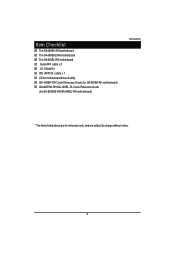
Item Checklist The GA-6KIEH-RH motherboard The GA-6KIEH2-RH motherboard The GA-6KIEL-RH motherboard Serial ATA cable x 2 I/O Shield Kit IDE (ATA100 ) cable x 1 CD for motherboard driver & utility GA--6KIEH-RH Quick Reference Guide (for GA-6KIEH-RH motherboard) GA-6KIEH2-RH/GA--6KIEL-RL Quick Reference Guide (for GA-6KIEH2-RH/GA-6KIEL-RH motherboard) Introduction * The items listed above are for reference only, and are subject to change without notice. 5
Item Checklist The GA-6KIEH-RH motherboard The GA-6KIEH2-RH motherboard The GA-6KIEL-RH motherboard Serial ATA cable x 2 I/O Shield Kit IDE (ATA100 ) cable x 1 CD for motherboard driver & utility GA--6KIEH-RH Quick Reference Guide (for GA-6KIEH-RH motherboard) GA-6KIEH2-RH/GA--6KIEL-RL Quick Reference Guide (for GA-6KIEH2-RH/GA-6KIEL-RH motherboard) Introduction * The items listed above are for reference only, and are subject to change without notice. 5
Manual
Page 6
...off the computer and unplug its components. 5. Before using the product, please verify that the power supply is best to be an unofficial Gigabyte product. 6 Product determined to wear an electrostatic discharge (ESD) cuff when handling electronic components (CPU, RAM). 4. Installation Notices 1. Prior... to system components as well as a result of the product, please consult a certified computer technician. GA-6KIEH-RH/GA-6KIEH2-RH/GA-6KIEL-RH Motherboard Chapter 1 Introduction 1-1 Considerations Prior to come in contact with the motherboard circuit or its power cord. 2.
...off the computer and unplug its components. 5. Before using the product, please verify that the power supply is best to be an unofficial Gigabyte product. 6 Product determined to wear an electrostatic discharge (ESD) cuff when handling electronic components (CPU, RAM). 4. Installation Notices 1. Prior... to system components as well as a result of the product, please consult a certified computer technician. GA-6KIEH-RH/GA-6KIEH2-RH/GA-6KIEL-RH Motherboard Chapter 1 Introduction 1-1 Considerations Prior to come in contact with the motherboard circuit or its power cord. 2.
Manual
Page 7
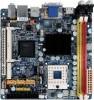
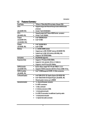
... Celeron M550 series processor y Socket P with 533MHz y Intel® GME965 MCH y Intel® ICH8M (GA-6KIEH2-RH) Chipset (GA-6KIEL-RH) Memory I/O Control Expansion Slots SATA Controller (GA-6KIEH-RH) SATA Controller y Intel® GLE960 MCH y Intel® ICH8M y 2 x DDR2 DIMM sockets y ..., ICH8M 1 Port) y Intel ® ICH8M supports 3 SATA 3.0 Gb/s connectors (GA-6KIEL-RH) On-Board Graphic Internal Connector y Intel® GMA X3100 3D Graphic Engine (GA-6KIEH-RH) y Intel® GMA X3000 3D Graphic Engine (GA-6KIEL-RH) y Shared system memory up to 256MB y 1 x 20-pin ATX power connector y...
... Celeron M550 series processor y Socket P with 533MHz y Intel® GME965 MCH y Intel® ICH8M (GA-6KIEH2-RH) Chipset (GA-6KIEL-RH) Memory I/O Control Expansion Slots SATA Controller (GA-6KIEH-RH) SATA Controller y Intel® GLE960 MCH y Intel® ICH8M y 2 x DDR2 DIMM sockets y ..., ICH8M 1 Port) y Intel ® ICH8M supports 3 SATA 3.0 Gb/s connectors (GA-6KIEL-RH) On-Board Graphic Internal Connector y Intel® GMA X3100 3D Graphic Engine (GA-6KIEH-RH) y Intel® GMA X3000 3D Graphic Engine (GA-6KIEL-RH) y Shared system memory up to 256MB y 1 x 20-pin ATX power connector y...
Manual
Page 8
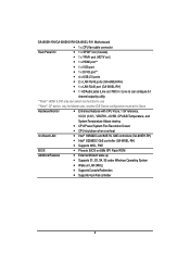
GA-6KIEH-RH/GA-6KIEH2-RH/GA-6KIEL-RH Motherboard y 1 x CPU fan cable connector Rear Panel I/O y 1 x SPDIF Out (Coaxial) y 1 x YPbPr prot (HDTV out ) y 1 x HDMI prot** y 1 x VGA port y 1 x DVI-D port** y 4 x USB 2.0 ports y 2 x LAN RJ45 ports (GA-6KIEH-RH) y 1 x LAN RJ45 port (GA-6KIEL-RH) y 1 HD Audio jacks (Line-out / MIC-... Detect y CPU shutdown when overheat On-Board LAN y Intel® 82566DC and 82573L GbE controllers (GA-6KIEH-RH) y Intel® 82566DC GbE controller (GA-6KIEL-RH) y Supports WOL, PXE BIOS y Phoenix BIOS on 8Mb SPI Flash ROM Additional Features y External...
GA-6KIEH-RH/GA-6KIEH2-RH/GA-6KIEL-RH Motherboard y 1 x CPU fan cable connector Rear Panel I/O y 1 x SPDIF Out (Coaxial) y 1 x YPbPr prot (HDTV out ) y 1 x HDMI prot** y 1 x VGA port y 1 x DVI-D port** y 4 x USB 2.0 ports y 2 x LAN RJ45 ports (GA-6KIEH-RH) y 1 x LAN RJ45 port (GA-6KIEL-RH) y 1 HD Audio jacks (Line-out / MIC-... Detect y CPU shutdown when overheat On-Board LAN y Intel® 82566DC and 82573L GbE controllers (GA-6KIEH-RH) y Intel® 82566DC GbE controller (GA-6KIEL-RH) y Supports WOL, PXE BIOS y Phoenix BIOS on 8Mb SPI Flash ROM Additional Features y External...
Manual
Page 11
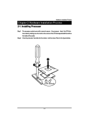
Hardware Installation Process Chapter 2 Hardware Installation Process 2-1: Installing Processor Step 1 Step 2 The processor socket come with the notch on the inside of the socket. Once the processor has slide into the socket by making sure the notch on the corner of the CPUcorresponds with a screw to the figures below. 1 2 Lock Unlock 11 Refer to secure the processor. Insert the CPU into the socket, lock the screw.
Hardware Installation Process Chapter 2 Hardware Installation Process 2-1: Installing Processor Step 1 Step 2 The processor socket come with the notch on the inside of the socket. Once the processor has slide into the socket by making sure the notch on the corner of the CPUcorresponds with a screw to the figures below. 1 2 Lock Unlock 11 Refer to secure the processor. Insert the CPU into the socket, lock the screw.
Manual
Page 12
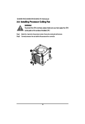
GA-6KIEH-RH/GA-6KIEH2-RH/GA-6KIEL-RH Motherboard 2-2: Installing Processor Colling Fan WARNING! ! To prevent the CPU overheat, please make sure you have apply the CPU cooler paste on the surface of installed CPU Step 1 Attach the heat sink n the procssor socket. Step 2 Connect processor fan can cable to the processor fan connector. 1 1 1 2 12 Secure the cooing fan with screws.
GA-6KIEH-RH/GA-6KIEH2-RH/GA-6KIEL-RH Motherboard 2-2: Installing Processor Colling Fan WARNING! ! To prevent the CPU overheat, please make sure you have apply the CPU cooler paste on the surface of installed CPU Step 1 Attach the heat sink n the procssor socket. Step 2 Connect processor fan can cable to the processor fan connector. 1 1 1 2 12 Secure the cooing fan with screws.

Manual
Page 13
The motherboard supports DDR2 memory module, whereby BIOS will automatically detect memory capacity and specifications. Installation Steps: Step 1. Firmly insert the DIMMinto the socket until the retaining clips snap back in the socket. Aling a DIMM on the socket such that the notch on the DIMM exactly match the notch in place. Reverse the installation steps if you want to remove the DIMM module. 13 The memory module only can be inserted in one direction. Step 2. 2-3: Install Memory Modules Hardware Installation Process Before installing the memory modules, please comply ...
The motherboard supports DDR2 memory module, whereby BIOS will automatically detect memory capacity and specifications. Installation Steps: Step 1. Firmly insert the DIMMinto the socket until the retaining clips snap back in the socket. Aling a DIMM on the socket such that the notch on the DIMM exactly match the notch in place. Reverse the installation steps if you want to remove the DIMM module. 13 The memory module only can be inserted in one direction. Step 2. 2-3: Install Memory Modules Hardware Installation Process Before installing the memory modules, please comply ...
Manual
Page 14
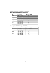
Supported DIMM Module Type (GA-6KIEL-RH) Size 256MB 512MB 1GB Organization 8MB x 8 x 4 bks 16MB x 16 x 4bks 16MB x 8 x 4bks 32MB x 16 x 4bks 32MB x 8 x 4bks 64MB x 16 x 4bks RAM Chips/DIMM 8 16 8 16 8 16 14 GA-6KIEH-RH/GA-6KIEH2-RH/GA-6KIEL-RH Motherboard Table 1. Supported DIMM Module Type (GA-6KIEH-RH) Size 256MB 512MB 1GB 2GB Organization 8MB x 8 x 4 bks 16MB x 16 x 4bks 16MB x 8 x 4bks 32MB x 16 x 4bks 32MB x 8 x 4bks 64MB x 16 x 4bks 32MB x 8 x 4bks 64MB x 16 x 4bks RAM Chips/DIMM 8 16 8 16 8 16 8 16 Table 2.
Supported DIMM Module Type (GA-6KIEL-RH) Size 256MB 512MB 1GB Organization 8MB x 8 x 4 bks 16MB x 16 x 4bks 16MB x 8 x 4bks 32MB x 16 x 4bks 32MB x 8 x 4bks 64MB x 16 x 4bks RAM Chips/DIMM 8 16 8 16 8 16 14 GA-6KIEH-RH/GA-6KIEH2-RH/GA-6KIEL-RH Motherboard Table 1. Supported DIMM Module Type (GA-6KIEH-RH) Size 256MB 512MB 1GB 2GB Organization 8MB x 8 x 4 bks 16MB x 16 x 4bks 16MB x 8 x 4bks 32MB x 16 x 4bks 32MB x 8 x 4bks 64MB x 16 x 4bks 32MB x 8 x 4bks 64MB x 16 x 4bks RAM Chips/DIMM 8 16 8 16 8 16 8 16 Table 2.
Manual
Page 15
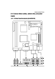
Hardware Installation Process 2-4: Connect ribbon cables, cabinet wires, and power supply 2-4-1 : I/O Back Panel Introduction (GA-6KIEH-RH) 15
Hardware Installation Process 2-4: Connect ribbon cables, cabinet wires, and power supply 2-4-1 : I/O Back Panel Introduction (GA-6KIEH-RH) 15
Manual
Page 16
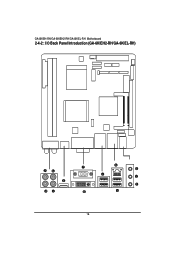
GA-6KIEH-RH/GA-6KIEH2-RH/GA-6KIEL-RH Motherboard 2-4-2 : I/O Back Panel Introduction (GA-6KIEH2-RH/GA-6KIEL-RH) 16
GA-6KIEH-RH/GA-6KIEH2-RH/GA-6KIEL-RH Motherboard 2-4-2 : I/O Back Panel Introduction (GA-6KIEH2-RH/GA-6KIEL-RH) 16
Manual
Page 17
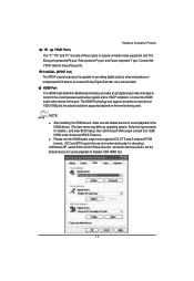
Hardware Installation Process / / YPbPr Ports The "Y," "Pb" and "Pr" are sets of 1920x1080p but the actual resolutions supported depend on better video equipment and TVs. Blue port represents Pb port, Red represnts Pr port, and Green represent Y port. Connect the YPbPr cable to this port. The HDMI Technology can support a maximum resolution of three inputs or outputs on the monitor being used. NOTE: After installing the HDMI device, make sure the default device for sound playback to transmit the uncompressed audio/video signals and is capable for details.), and enter BIOS Setup, ...
Hardware Installation Process / / YPbPr Ports The "Y," "Pb" and "Pr" are sets of 1920x1080p but the actual resolutions supported depend on better video equipment and TVs. Blue port represents Pb port, Red represnts Pr port, and Green represent Y port. Connect the YPbPr cable to this port. The HDMI Technology can support a maximum resolution of three inputs or outputs on the monitor being used. NOTE: After installing the HDMI device, make sure the default device for sound playback to transmit the uncompressed audio/video signals and is capable for details.), and enter BIOS Setup, ...
Manual
Page 18
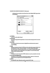
GA-6KIEH-RH/GA-6KIEH2-RH/GA-6KIEL-RH Motherboard In Windows Vista, select Start>Control Panel>Sound, select Realtek HDMI Output and then click Set Default. Connect a monitor that supports DVI-D connection to ...
GA-6KIEH-RH/GA-6KIEH2-RH/GA-6KIEL-RH Motherboard In Windows Vista, select Start>Control Panel>Sound, select Realtek HDMI Output and then click Set Default. Connect a monitor that supports DVI-D connection to ...
Manual
Page 19
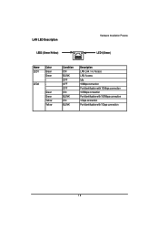
LAN LED Description LED2 (Green/Yellow) Hardware Installation Process LED1 (Green) Name LED1 LED2 Color Green Green Green Green Yellow Yellow Condition ON BLINK OFF OFF OFF ON BLINK ON BLINK Description LAN Link / no Access LAN Access Idle 10Mbps connection Port identification with 10 Mbps connection 100Mbps connection Port identification with 100Mbps connection 1Gbps connection Port identification with 1Gbps connection 19
LAN LED Description LED2 (Green/Yellow) Hardware Installation Process LED1 (Green) Name LED1 LED2 Color Green Green Green Green Yellow Yellow Condition ON BLINK OFF OFF OFF ON BLINK ON BLINK Description LAN Link / no Access LAN Access Idle 10Mbps connection Port identification with 10 Mbps connection 100Mbps connection Port identification with 100Mbps connection 1Gbps connection Port identification with 1Gbps connection 19
Manual
Page 20
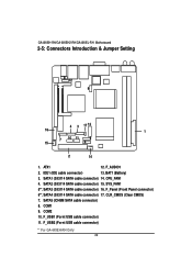
... connector) 17. SATA2 (SiI3114 SATA cable connector) 15. COM1 9. IDE1 (IDE cable connector) 13. CPU_FAN1 4. CLR_CMOS (Clear CMOS) 7. F_USB1 (Fornt USB cable connector) 11. GA-6KIEH-RH/GA-6KIEH2-RH/GA-6KIEL-RH Motherboard 2-5: Connectors Introduction & Jumper Setting 8 12 9 4 3 17 13 16 1 15 7 10 11 5 6 2 14 1. SATA3 (SiI3114 SATA cable connector) 16. F_USB2 (Fornt USB cable connector...
... connector) 17. SATA2 (SiI3114 SATA cable connector) 15. COM1 9. IDE1 (IDE cable connector) 13. CPU_FAN1 4. CLR_CMOS (Clear CMOS) 7. F_USB1 (Fornt USB cable connector) 11. GA-6KIEH-RH/GA-6KIEH2-RH/GA-6KIEL-RH Motherboard 2-5: Connectors Introduction & Jumper Setting 8 12 9 4 3 17 13 16 1 15 7 10 11 5 6 2 14 1. SATA3 (SiI3114 SATA cable connector) 16. F_USB2 (Fornt USB cable connector...

Manual
Page 21
One IDE connector can then connect to two IDE devices (hard drive or optical drive). If you want to connect two IDE devices, please set the jumper on one IDE cable, and the single IDE cable can connect to one IDE device as Master and the other related devices are firmly connected to the mainboard. 20 10 1 11 Pin No. 1 2 3 4 5 6 7 8 9 10 11 12 13 14 15 16 17 18 19 20 Definition 3.3V 3.3V GND VCC GND VCC GND Power Good 5V SB(stand by +5V) +12V 3.3V -12V GND PS_ON(softOn/Off) GND GND GND -5V VCC VCC 2 ) IDE1 (IDE cable connector) An IDE device connects to the instructions located on the...
One IDE connector can then connect to two IDE devices (hard drive or optical drive). If you want to connect two IDE devices, please set the jumper on one IDE cable, and the single IDE cable can connect to one IDE device as Master and the other related devices are firmly connected to the mainboard. 20 10 1 11 Pin No. 1 2 3 4 5 6 7 8 9 10 11 12 13 14 15 16 17 18 19 20 Definition 3.3V 3.3V GND VCC GND VCC GND Power Good 5V SB(stand by +5V) +12V 3.3V -12V GND PS_ON(softOn/Off) GND GND GND -5V VCC VCC 2 ) IDE1 (IDE cable connector) An IDE device connects to the instructions located on the...
Manual
Page 22
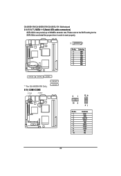
GA-6KIEH-RH/GA-6KIEH2-RH/GA-6KIEL-RH Motherboard 3/ 4/ 5/ 6/ 7 ) SATA 1~5 (Serial ATA cable connectors) SATA 3Gb/s can provide up to work properly. 7 1 Pin No. 1 2 3 4 5 6 7 Definition GND TXP TXN GND RXN RXP GND SATA5 SATA2 SATA1 ** For GA-6KIEH-RH Only 8/ 9 ) COM1/COM2 COM1 COM2 SATA3** SATA4** 91 10 9 10 2 21 Pin No. 1 2 3 4 5 6 7 8 9 10 Definition DCDSIN2 SOUT2 DTR2GND DSR2RTS2CTS2RI2NC 22 Please refer to the BIOS setting for the SATA 3Gb/s and install the proper driver in order to 300MB/s stransfer rate.
GA-6KIEH-RH/GA-6KIEH2-RH/GA-6KIEL-RH Motherboard 3/ 4/ 5/ 6/ 7 ) SATA 1~5 (Serial ATA cable connectors) SATA 3Gb/s can provide up to work properly. 7 1 Pin No. 1 2 3 4 5 6 7 Definition GND TXP TXN GND RXN RXP GND SATA5 SATA2 SATA1 ** For GA-6KIEH-RH Only 8/ 9 ) COM1/COM2 COM1 COM2 SATA3** SATA4** 91 10 9 10 2 21 Pin No. 1 2 3 4 5 6 7 8 9 10 Definition DCDSIN2 SOUT2 DTR2GND DSR2RTS2CTS2RI2NC 22 Please refer to the BIOS setting for the SATA 3Gb/s and install the proper driver in order to 300MB/s stransfer rate.