
User Manual
Page 2
English GA-3PXSL-RH Motherboard Table of Content Item Checklist 4 WARNING 4 Chapter 1 Introduction 5 1.1.Features Summary 5 1.2GA-3PXSL-RH Motherboard Components 7 Chapter 2Hardware Installation Process 9 2-1: Installing Processor and CPU Haet Sink 9 2-1-1: Installing CPU ...9 ... 2-4-1 : I/O Back Panel Introduction 14 2-5: Connectors & Jumper Setting Introduction 16 2-6: Block Diagram 24 Chapter 3 BIOS Setup 25 Main ...27 Advanced 32 Advanced BIOS Feature 33 Advanced Chipset ...36 Integrated Peripherals ...38 Power Management Setup 46 PnP/PCI Configuration ...48 Security ...50 ...
English GA-3PXSL-RH Motherboard Table of Content Item Checklist 4 WARNING 4 Chapter 1 Introduction 5 1.1.Features Summary 5 1.2GA-3PXSL-RH Motherboard Components 7 Chapter 2Hardware Installation Process 9 2-1: Installing Processor and CPU Haet Sink 9 2-1-1: Installing CPU ...9 ... 2-4-1 : I/O Back Panel Introduction 14 2-5: Connectors & Jumper Setting Introduction 16 2-6: Block Diagram 24 Chapter 3 BIOS Setup 25 Main ...27 Advanced 32 Advanced BIOS Feature 33 Advanced Chipset ...36 Integrated Peripherals ...38 Power Management Setup 46 PnP/PCI Configuration ...48 Security ...50 ...

User Manual
Page 6
compliant ACPI defined S1, S3, and S5 PS/2 Mouse power on under Windows Operating System External Modem wake up Supports S1, S3, S5 under Windows Operating System Wake on 4MB flash ROM SMBIOS Spec. English GA-3PXSL-RH Motherboard BIOS Additional Features Licensed Award BIOS on LAN (WOL) AC Recovery 6 Rev 2.3.3.
compliant ACPI defined S1, S3, and S5 PS/2 Mouse power on under Windows Operating System External Modem wake up Supports S1, S3, S5 under Windows Operating System Wake on 4MB flash ROM SMBIOS Spec. English GA-3PXSL-RH Motherboard BIOS Additional Features Licensed Award BIOS on LAN (WOL) AC Recovery 6 Rev 2.3.3.

User Manual
Page 11
It supports the Dual Channel Technology. Wrong orientation will automatically detects memory type and size. Please change the insert orientation. To install the memory module, just push it vertically into the DIMM socket .The DIMM module can vary between sockets. 2-2: Install memory modules Hardware Installation Process GA-3PXSL-RH has 4 dual inline memory module (DIMM) socets. CHANNEL B CHANNEL A 11 The BIOS will cause improper installation. Memory size can only fit in one direction due to the notch.
It supports the Dual Channel Technology. Wrong orientation will automatically detects memory type and size. Please change the insert orientation. To install the memory module, just push it vertically into the DIMM socket .The DIMM module can vary between sockets. 2-2: Install memory modules Hardware Installation Process GA-3PXSL-RH has 4 dual inline memory module (DIMM) socets. CHANNEL B CHANNEL A 11 The BIOS will cause improper installation. Memory size can only fit in one direction due to the notch.

User Manual
Page 13
... of the expansion card. 6. Power on the card are indeed seated in motherboard. 4. Replace the screw to secure the slot bracket of expansion card from BIOS. 8. Install related driver from the computer. 3. Read the related expansion card's instruction document before install the expansion card into expansion slot in the slot. 5. Press...
... of the expansion card. 6. Power on the card are indeed seated in motherboard. 4. Replace the screw to secure the slot bracket of expansion card from BIOS. 8. Install related driver from the computer. 3. Read the related expansion card's instruction document before install the expansion card into expansion slot in the slot. 5. Press...

User Manual
Page 25
... program that it retains the Setup information when the power is turned off. This type of information is an overview of the BIOS Setup Program. Chapter 3 BIOS Setup BIOS Setup BIOS Setup is stored in battery-backed CMOS RAM so that allows users to Main Menu Increase the numeric value or make changes Decrease...
... program that it retains the Setup information when the power is turned off. This type of information is an overview of the BIOS Setup Program. Chapter 3 BIOS Setup BIOS Setup BIOS Setup is stored in battery-backed CMOS RAM so that allows users to Main Menu Increase the numeric value or make changes Decrease...

User Manual
Page 26
... function features. z Boot This setup page include all the items in standard compatible BIOS. z Exit Save CMOS value settings to CMOS and exit setup or abandon all the items of the screen. To exit the Help Window press . GA-3PXSL-RH Motherboard GETTINGHELP Main Menu The on-line description of the highlighted setup...
... function features. z Boot This setup page include all the items in standard compatible BIOS. z Exit Save CMOS value settings to CMOS and exit setup or abandon all the items of the screen. To exit the Help Window press . GA-3PXSL-RH Motherboard GETTINGHELP Main Menu The on-line description of the highlighted setup...
User Manual
Page 27
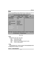
... The times format is 13:00:00. Use arrow keys to select among the items and press to Sunday. The time is , , . Main BIOS Setup Once you enter Award BIOS Setup Utility, the Main Menu (Figure 1) will appear on the 24hour military-time clock. The month, Jan. Jan. 29 2006 Item Help...
... The times format is 13:00:00. Use arrow keys to select among the items and press to Sunday. The time is , , . Main BIOS Setup Once you enter Award BIOS Setup Utility, the Main Menu (Figure 1) will appear on the 24hour military-time clock. The month, Jan. Jan. 29 2006 Item Help...
User Manual
Page 28
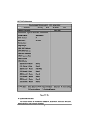
GA-3PXSL-RH Motherboard Phoenix-Award WorkstationBIOS CMOS Setup Utility Main Advanced Security Boot PC Health Exit System Information Item Help System Information Product Name: GA-XXXXXX BIOS Version: F1 Build Date: xx-xx-xx Manufactory: Chipset Type: LAN1 MAC Address: LAN2 MAC Address: CPU Core Frequency CPU Frequency ...ESC: Exit F1: General Help F5: Previous Values F7: Optimized Defaults Figure 1-1: Main System Information This category includes the information of motherboard, BIOS version, Build Date, Manufactory, relative chipset type, and processors information. 28
GA-3PXSL-RH Motherboard Phoenix-Award WorkstationBIOS CMOS Setup Utility Main Advanced Security Boot PC Health Exit System Information Item Help System Information Product Name: GA-XXXXXX BIOS Version: F1 Build Date: xx-xx-xx Manufactory: Chipset Type: LAN1 MAC Address: LAN2 MAC Address: CPU Core Frequency CPU Frequency ...ESC: Exit F1: General Help F5: Previous Values F7: Optimized Defaults Figure 1-1: Main System Information This category includes the information of motherboard, BIOS version, Build Date, Manufactory, relative chipset type, and processors information. 28

User Manual
Page 29
... is user-definable; Such information should be asked to enter to the following items. Enter the information directly from drive C to set hard drive parameters. BIOS Setup IDE Channel 0~5 Master / Channel 0~1 Slave The category identifies the types of sectors If a hard disk has not been installed, select NONE and press . 29...
... is user-definable; Such information should be asked to enter to the following items. Enter the information directly from drive C to set hard drive parameters. BIOS Setup IDE Channel 0~5 Master / Channel 0~1 Slave The category identifies the types of sectors If a hard disk has not been installed, select NONE and press . 29...

User Manual
Page 30
Both Drive A & B are 3 mode Floppy Drives. GA-3PXSL-RH Motherboard Drive A The category identifies the types of 1.2MB (as opposed 1.44MB) on a 3.5-inch diskette. None No floppy drive installed 360K, 51/4 in. 5.25 ... capacity (3.5 inch when 3 Mode is required to halt when an error is 3 mode Floppy Drive. Floppy 3 Mode Support will be stopped. All Errors Whenever the BIOS detects a non-fatal error the system boot will allow reading and writing of floppy disk drive A that may be prompted. All, But Keyboard The system...
Both Drive A & B are 3 mode Floppy Drives. GA-3PXSL-RH Motherboard Drive A The category identifies the types of 1.2MB (as opposed 1.44MB) on a 3.5-inch diskette. None No floppy drive installed 360K, 51/4 in. 5.25 ... capacity (3.5 inch when 3 Mode is required to halt when an error is 3 mode Floppy Drive. Floppy 3 Mode Support will be stopped. All Errors Whenever the BIOS detects a non-fatal error the system boot will allow reading and writing of floppy disk drive A that may be prompted. All, But Keyboard The system...
User Manual
Page 31
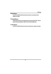
Total Memory The POST of the BIOS will determine the amount of total memory installed in the system. 31 BIOS Setup Base Memory The POST of the BIOS will determine the amount of base (or conventional) memory installed in the system. Extended Memory The BIOS determines how much extended memory is the amount of memory located above 1 MB in the C PU's memory address map. This is present during the POST.
Total Memory The POST of the BIOS will determine the amount of total memory installed in the system. 31 BIOS Setup Base Memory The POST of the BIOS will determine the amount of base (or conventional) memory installed in the system. Extended Memory The BIOS determines how much extended memory is the amount of memory located above 1 MB in the C PU's memory address map. This is present during the POST.

User Manual
Page 32
GA-3PXSL-RH Motherboard Advanced Phoenix-Award WorkstationBIOS CMOS Setup Utility Main Advanced Security Boot PC Health Exit Advanced BIOS Feature Item Help Advanced Chipset Integrated Peripherals Power Management Setup PnP/PCI Configuration K L J I : Move Enter: Select +/-/PU/PD: Value F10: Save ESC: Exit F1: General Help F5: Previous Values F7: Optimized Defaults Figure 2: Advanced 32
GA-3PXSL-RH Motherboard Advanced Phoenix-Award WorkstationBIOS CMOS Setup Utility Main Advanced Security Boot PC Health Exit Advanced BIOS Feature Item Help Advanced Chipset Integrated Peripherals Power Management Setup PnP/PCI Configuration K L J I : Move Enter: Select +/-/PU/PD: Value F10: Save ESC: Exit F1: General Help F5: Previous Values F7: Optimized Defaults Figure 2: Advanced 32

User Manual
Page 33
... POST.(Default value) Disabled Normal POST. 33 If it is set to Enable, BIOS will shorten or skip some check items during POST. Advanced BIOS Feature BIOS Setup Phoenix-Award WorkstationBIOS CMOS Setup Utility Advanced Advanced BIOS Feature Item Help Quick Power On Self Test [Enabled] Boot Up Floppy Seek [... K L J I : Move Enter: Select +/-/PU/PD: Value F10: Save ESC: Exit F1: General Help F5: Previous Values F7: Optimized Defaults Figure 2-1: Advanced BIOS Features Quick Power On Self Test This category speeds up Power On Self Test (POST) after you power on the computer.
... POST.(Default value) Disabled Normal POST. 33 If it is set to Enable, BIOS will shorten or skip some check items during POST. Advanced BIOS Feature BIOS Setup Phoenix-Award WorkstationBIOS CMOS Setup Utility Advanced Advanced BIOS Feature Item Help Quick Power On Self Test [Enabled] Boot Up Floppy Seek [... K L J I : Move Enter: Select +/-/PU/PD: Value F10: Save ESC: Exit F1: General Help F5: Previous Values F7: Optimized Defaults Figure 2-1: Advanced BIOS Features Quick Power On Self Test This category speeds up Power On Self Test (POST) after you power on the computer.

User Manual
Page 34
... this function. Clear all DMI Event Log Yes System will clear DMI event logs at next POST stage. (Default value) 34 GA-3PXSL-RH Motherboard Boot Up Floppy Seek During POST, BIOS will determine the floppy disk drive installed is 40 or 80 tracks. 360K type is 40 tracks 720K, 1.2M and 1.44M... are all 80 tracks. (Default value) Disabled BIOS will not search for NumLock. Note that there will not be any warning message if the drive installed is 360K. No Do not clear DMI...
... this function. Clear all DMI Event Log Yes System will clear DMI event logs at next POST stage. (Default value) 34 GA-3PXSL-RH Motherboard Boot Up Floppy Seek During POST, BIOS will determine the floppy disk drive installed is 40 or 80 tracks. 360K type is 40 tracks 720K, 1.2M and 1.44M... are all 80 tracks. (Default value) Disabled BIOS will not search for NumLock. Note that there will not be any warning message if the drive installed is 360K. No Do not clear DMI...

User Manual
Page 35
BIOS Setup Mark DMI Events Log as Read This option allows user to clear all DMI event logs immediately. Hit [Y] and [Enter] to clear all DMI event logs. Event Log Capacity This item displays the information of Event Log Vaildity. 35 Events Log Vaildity This item displays the information of Event Log Capacity. View DMI Event Log Press [Enter] to view all DMI Event Logs immediately. Press [Enter] will pop up a confirmation window.
BIOS Setup Mark DMI Events Log as Read This option allows user to clear all DMI event logs immediately. Hit [Y] and [Enter] to clear all DMI event logs. Event Log Capacity This item displays the information of Event Log Vaildity. 35 Events Log Vaildity This item displays the information of Event Log Capacity. View DMI Event Log Press [Enter] to view all DMI Event Logs immediately. Press [Enter] will pop up a confirmation window.

User Manual
Page 36
GA-3PXSL-RH Motherboard Advanced Chipset Phoenix-Award WorkstationBIOS CMOS Setup Utility Advanced Advanced Chipset Item Help OnChip VGA [Enabled] Frame Buffer Size [64M] System BIOS Cacheable [Disabled] K L J I : Move Enter: Select +/-/PU/PD: Value F10: Save ESC: Exit F1: General Help F5: Previous Values F7: Optimized Defaults Figure 2-2: Advanced Chipset 36
GA-3PXSL-RH Motherboard Advanced Chipset Phoenix-Award WorkstationBIOS CMOS Setup Utility Advanced Advanced Chipset Item Help OnChip VGA [Enabled] Frame Buffer Size [64M] System BIOS Cacheable [Disabled] K L J I : Move Enter: Select +/-/PU/PD: Value F10: Save ESC: Exit F1: General Help F5: Previous Values F7: Optimized Defaults Figure 2-2: Advanced Chipset 36

User Manual
Page 37
System BIOS Cacheable Enabled Enable System BIOS Cacheable function. Frame Buffer Size This item allows user to select the frame buffer size. Disabled Disabled this device. Options 16M, 32M, 64M, 128MB, 256MB. OnChip VGA Enabled Disabled Enable Onboard VGA chipset. (Default value) Disable this function. (Default value) BIOS Setup 37
System BIOS Cacheable Enabled Enable System BIOS Cacheable function. Frame Buffer Size This item allows user to select the frame buffer size. Disabled Disabled this device. Options 16M, 32M, 64M, 128MB, 256MB. OnChip VGA Enabled Disabled Enable Onboard VGA chipset. (Default value) Disable this function. (Default value) BIOS Setup 37

User Manual
Page 39
IDE Function Setup BIOS Setup OnChip IDE Channel 0 Enabled Enable onboard Onchip IDE Channel 0. (Default value) Disabled Disable this function. Mode 4 Select Mode 4 as IDE secondary slave PIO. Mode 4 ...
IDE Function Setup BIOS Setup OnChip IDE Channel 0 Enabled Enable onboard Onchip IDE Channel 0. (Default value) Disabled Disable this function. Mode 4 Select Mode 4 as IDE secondary slave PIO. Mode 4 ...

User Manual
Page 41
SATA-1 Only enable SATA-1 device. BIOS Setup 41 IDE Prefetch Mode Enabled Enable IDE Prefetch Mode. (Default value) Disabled Disable this function. IDE DMA transfer access Enabled Enable IDE DMA transfer access. (Default value) Disabled Disable this function. Serial-ATA Controller All Enabled Enable all serial device controllers. (Default value) Disabled Disable this device.
SATA-1 Only enable SATA-1 device. BIOS Setup 41 IDE Prefetch Mode Enabled Enable IDE Prefetch Mode. (Default value) Disabled Disable this function. IDE DMA transfer access Enabled Enable IDE DMA transfer access. (Default value) Disabled Disable this function. Serial-ATA Controller All Enabled Enable all serial device controllers. (Default value) Disabled Disable this device.
User Manual
Page 43
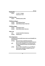
... Mouse Support. (Default value) MAC LAN Auto Disabled Auto detect onboard H/W LAN. (Default value) Disable this function. MAC Media Interface This BIOS feature determines which MAC interface is V1.1+V2.0 BIOS Setup USB Memory Type Options SHADOW, Base Memory (640K). This allows transfers of up to the external PHY devices. Pin Strap...
... Mouse Support. (Default value) MAC LAN Auto Disabled Auto detect onboard H/W LAN. (Default value) Disable this function. MAC Media Interface This BIOS feature determines which MAC interface is V1.1+V2.0 BIOS Setup USB Memory Type Options SHADOW, Base Memory (640K). This allows transfers of up to the external PHY devices. Pin Strap...


