
User Manual
Page 2
English GA-3PXSL-RH Motherboard Table of Content Item Checklist 4 WARNING 4 Chapter 1 Introduction 5 1.1.Features Summary 5 1.2GA-3PXSL-RH Motherboard Components 7 Chapter 2Hardware Installation Process 9 2-1: Installing Processor and CPU Haet Sink 9 2-1-1: Installing CPU ...9 2-1-2: Installing CPU Cooler Fan 10 2-2: Install memory modules 11 2-3: Install expansion cards 13 2-4: Connect ribbon cables, cabinet wires, and power supply 14 2-4-1 : I/O Back...
English GA-3PXSL-RH Motherboard Table of Content Item Checklist 4 WARNING 4 Chapter 1 Introduction 5 1.1.Features Summary 5 1.2GA-3PXSL-RH Motherboard Components 7 Chapter 2Hardware Installation Process 9 2-1: Installing Processor and CPU Haet Sink 9 2-1-1: Installing CPU ...9 2-1-2: Installing CPU Cooler Fan 10 2-2: Install memory modules 11 2-3: Install expansion cards 13 2-4: Connect ribbon cables, cabinet wires, and power supply 14 2-4-1 : I/O Back...
User Manual
Page 5
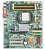
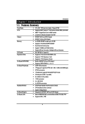
Chapter 1 Introduction Introduction 1.1. Features Summary Form Factor CPU Chipset Memory I/O Control Expansion Slots On-Board SATA RAID On-Board Peripherals Hardware Monitor On-Board Graphic On-Board LAN 12" x 9.6" ATX size form factor, 4 layers PCB ... 6150 Chipset NVIDIA® nForce 430 Chipset 4 x DDRII-533/667 socket up to 16 GB Supports Un-buffered DDRII 533/667 Dual Channel memory bus Support 512MB, and 1GB memory Single-bit Errors Correction, Multiple-bit Errors Detection ITE IT8712F-A Super I/O Supports 3 PCI slots 32-Bit/33MHz (5V) Supports 1 PCI-Express x1...
Chapter 1 Introduction Introduction 1.1. Features Summary Form Factor CPU Chipset Memory I/O Control Expansion Slots On-Board SATA RAID On-Board Peripherals Hardware Monitor On-Board Graphic On-Board LAN 12" x 9.6" ATX size form factor, 4 layers PCB ... 6150 Chipset NVIDIA® nForce 430 Chipset 4 x DDRII-533/667 socket up to 16 GB Supports Un-buffered DDRII 533/667 Dual Channel memory bus Support 512MB, and 1GB memory Single-bit Errors Correction, Multiple-bit Errors Detection ITE IT8712F-A Super I/O Supports 3 PCI slots 32-Bit/33MHz (5V) Supports 1 PCI-Express x1...

User Manual
Page 11
Wrong orientation will automatically detects memory type and size. Memory size can only fit in one direction due to the notch. 2-2: Install memory modules Hardware Installation Process GA-3PXSL-RH has 4 dual inline memory module (DIMM) socets. Please change the insert orientation. CHANNEL B CHANNEL A 11 To install the memory module, just push it vertically into the DIMM socket .The DIMM module can vary between sockets. The BIOS will cause improper installation. It supports the Dual Channel Technology.
Wrong orientation will automatically detects memory type and size. Memory size can only fit in one direction due to the notch. 2-2: Install memory modules Hardware Installation Process GA-3PXSL-RH has 4 dual inline memory module (DIMM) socets. Please change the insert orientation. CHANNEL B CHANNEL A 11 To install the memory module, just push it vertically into the DIMM socket .The DIMM module can vary between sockets. The BIOS will cause improper installation. It supports the Dual Channel Technology.
User Manual
Page 27
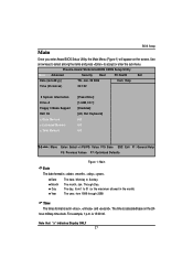
... maximum allowed in , and . Jan. 29 2006 Item Help Time (hh:mm:ss) 23:1:52 System Information Drive A Floppy 3 Mode Support Halt On x Base Memory x Extended Memory x Total Memory [Press Enter] [1.44M, 3.51/2] [Disabled] [All, But Keyboard] KB KB KB K L J I : Move Enter: Select +/-/PU/PD: Value F10: Save ESC: Exit F1: General Help...
... maximum allowed in , and . Jan. 29 2006 Item Help Time (hh:mm:ss) 23:1:52 System Information Drive A Floppy 3 Mode Support Halt On x Base Memory x Extended Memory x Total Memory [Press Enter] [1.44M, 3.51/2] [Disabled] [All, But Keyboard] KB KB KB K L J I : Move Enter: Select +/-/PU/PD: Value F10: Save ESC: Exit F1: General Help...
User Manual
Page 31
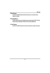
This is present during the POST. Total Memory The POST of the BIOS will determine the amount of base (or conventional) memory installed in the system. BIOS Setup Base Memory The POST of the BIOS will determine the amount of total memory installed in the system. 31 Extended Memory The BIOS determines how much extended memory is the amount of memory located above 1 MB in the C PU's memory address map.
This is present during the POST. Total Memory The POST of the BIOS will determine the amount of base (or conventional) memory installed in the system. BIOS Setup Base Memory The POST of the BIOS will determine the amount of total memory installed in the system. 31 Extended Memory The BIOS determines how much extended memory is the amount of memory located above 1 MB in the C PU's memory address map.

User Manual
Page 38
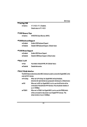
GA-3PXSL-RH Motherboard Integrated Peripherals Phoenix-Award WorkstationBIOS CMOS Setup Utility Advanced Integrated Peripherals Item Help IDE Function Setup RAID Config OnChip USB [V1.1+V2.0] USB Memory Type [SHADOW] USB Keyboard Support [Disabled] USB Mouse Support [Disabled] MAC Lan [Auto] MAC Media Interface [Pin Strap] 2nd Lan Controller [Auto] IDE HDD Block ...
GA-3PXSL-RH Motherboard Integrated Peripherals Phoenix-Award WorkstationBIOS CMOS Setup Utility Advanced Integrated Peripherals Item Help IDE Function Setup RAID Config OnChip USB [V1.1+V2.0] USB Memory Type [SHADOW] USB Keyboard Support [Disabled] USB Mouse Support [Disabled] MAC Lan [Auto] MAC Media Interface [Pin Strap] 2nd Lan Controller [Auto] IDE HDD Block ...
User Manual
Page 43
.... RGMII When set to RGMII, the Gigabit MAC is set to use the MII which MAC interface is V1.1+V2.0 BIOS Setup USB Memory Type Options SHADOW, Base Memory (640K). Default value is used to connect the Gigabit MAC to 100Mbps. OnChip USB Options V1.1+V2.0, V1.1, Disabled. MAC Media Interface This...
.... RGMII When set to RGMII, the Gigabit MAC is set to use the MII which MAC interface is V1.1+V2.0 BIOS Setup USB Memory Type Options SHADOW, Base Memory (640K). Default value is used to connect the Gigabit MAC to 100Mbps. OnChip USB Options V1.1+V2.0, V1.1, Disabled. MAC Media Interface This...

User Manual
Page 49
... will also solve the problem of the boot and Plug & Play compatible devices. It corrects incorrect color reproduction by "snooping" into the graphics card's framebuffer memory and modifying (synchronizing) the information delivered from the graphics card's Feature Connector to set this function. (Default value) Maximum Payloads Size This option provides function...
... will also solve the problem of the boot and Plug & Play compatible devices. It corrects incorrect color reproduction by "snooping" into the graphics card's framebuffer memory and modifying (synchronizing) the information delivered from the graphics card's Feature Connector to set this function. (Default value) Maximum Payloads Size This option provides function...
User Manual
Page 69
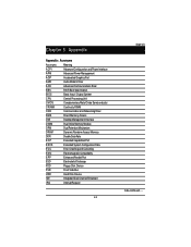
... Processing Unit CMOS Complementary Metal Oxide Semiconductor CRIMM Continuity RIMM CNR Communication and Networking Riser DMA Direct Memory Access DMI Desktop Management Interface DIMM Dual Inline Memory Module DRM Dual Retention Mechanism DRAM Dynamic Random Access Memory DDR Double Data Rate ECP Extended Capabilities Port ESCD Extended System Configuration Data ECC Error Checking...
... Processing Unit CMOS Complementary Metal Oxide Semiconductor CRIMM Continuity RIMM CNR Communication and Networking Riser DMA Direct Memory Access DMI Desktop Management Interface DIMM Dual Inline Memory Module DRM Dual Retention Mechanism DRAM Dynamic Random Access Memory DDR Double Data Rate ECP Extended Capabilities Port ESCD Extended System Configuration Data ECC Error Checking...


