Manual
Page 1
GA-3CESL3-RH AMD Socket F Dual Processor Motherboard USER'S MANUAL AMD Opteron™ Socket F Dual Processor Motherboard Rev. 1601 * The WEEE marking on the product indicates this product must not be disposed of with user's other household waste and must be handed over to a designated collection point for the recycling of waste electrical and electronic equipment!! * The WEEE marking applies only in European Union's member states.
GA-3CESL3-RH AMD Socket F Dual Processor Motherboard USER'S MANUAL AMD Opteron™ Socket F Dual Processor Motherboard Rev. 1601 * The WEEE marking on the product indicates this product must not be disposed of with user's other household waste and must be handed over to a designated collection point for the recycling of waste electrical and electronic equipment!! * The WEEE marking applies only in European Union's member states.
Manual
Page 2
... Table of Content Item Checklist 3 WARNING 3 Chapter 1 Introduction 4 1.1 Features Summary 4 1.2 GA-3CESL3-RH Motherboard Components 6 Chapter 2 Hardware Installation Process 8 2-1: Installing Processor and CPU Haet Sink 8 2-1-1: Installing CPU ...8 2-1-2: Installing Heat Sink 9 2-2: Install Memory Modules 10 2-3: Connect ribbon cables, cabinet ...
... Table of Content Item Checklist 3 WARNING 3 Chapter 1 Introduction 4 1.1 Features Summary 4 1.2 GA-3CESL3-RH Motherboard Components 6 Chapter 2 Hardware Installation Process 8 2-1: Installing Processor and CPU Haet Sink 8 2-1-1: Installing CPU ...8 2-1-2: Installing Heat Sink 9 2-2: Install Memory Modules 10 2-3: Connect ribbon cables, cabinet ...
Manual
Page 3
... electricity, you should follow some precautions whenever you can still attach the spacers to the chassis... Item Checklist GA-3CESL3-RH motherboard Serial ATA cable x 6 IDE (ATA133 ) cable x 1 / Floppy cable x 1 CD for motherboard driver & utility Introduction GA-3CESL3-RH Quick Reference Guide I/O Shield Kit SATA Power cable x 3 WARNING! Use a grounded wrist strap before you do not...
... electricity, you should follow some precautions whenever you can still attach the spacers to the chassis... Item Checklist GA-3CESL3-RH motherboard Serial ATA cable x 6 IDE (ATA133 ) cable x 1 / Floppy cable x 1 CD for motherboard driver & utility Introduction GA-3CESL3-RH Quick Reference Guide I/O Shield Kit SATA Power cable x 3 WARNING! Use a grounded wrist strap before you do not...
Manual
Page 4
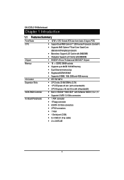
... Software RAID 0,1,0+1, 5 y Supports 6 SATA 3.0 Gb/s connectors y 1 ATA connector y 1 Floppy connector y 6 SATA 3.0 Gb/s connectors y 2 PS/2 connectors y 1 VGA y 1 Serial port (COM) y 6 x USB 2.0 (4 by cable) y 2 x LAN RJ45 4 English GA-3CESL3-RH Motherboard Chapter 1 Introduction 1.1 Features Summary Form Factor CPU y 12"W x 13"D Extend ATX size form factor, 8 layers PCB.
... Software RAID 0,1,0+1, 5 y Supports 6 SATA 3.0 Gb/s connectors y 1 ATA connector y 1 Floppy connector y 6 SATA 3.0 Gb/s connectors y 2 PS/2 connectors y 1 VGA y 1 Serial port (COM) y 6 x USB 2.0 (4 by cable) y 2 x LAN RJ45 4 English GA-3CESL3-RH Motherboard Chapter 1 Introduction 1.1 Features Summary Form Factor CPU y 12"W x 13"D Extend ATX size form factor, 8 layers PCB.
Manual
Page 5
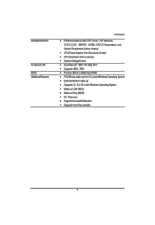
Hardware Monitor On-Board LAN BIOS Additional Features Introduction y Enhanced features with CPU Vcore, 1.5V reference, VCC3 (3.3V) , VBAT3V, +5VSB, CPU1/2 Temperature, and System Temperature Values viewing y CPU/Power/System Fan Revolution Detect y CPU shutdown when overheat y System Voltage Detect y Dual Marvell® 88E1116 GbE PHY y Supports WOL, PXE y Phoenix BIOS on 8Mb flash ROM y PS/2 Mouse wake up from S1 under Windows Operating System y External Modem wake up y Supports S1, S4, S5 under Windows Operating System y Wake on LAN (WOL) y Wake on Ring (WOR) y AC Recovery y Supports ...
Hardware Monitor On-Board LAN BIOS Additional Features Introduction y Enhanced features with CPU Vcore, 1.5V reference, VCC3 (3.3V) , VBAT3V, +5VSB, CPU1/2 Temperature, and System Temperature Values viewing y CPU/Power/System Fan Revolution Detect y CPU shutdown when overheat y System Voltage Detect y Dual Marvell® 88E1116 GbE PHY y Supports WOL, PXE y Phoenix BIOS on 8Mb flash ROM y PS/2 Mouse wake up from S1 under Windows Operating System y External Modem wake up y Supports S1, S4, S5 under Windows Operating System y Wake on LAN (WOL) y Wake on Ring (WOR) y AC Recovery y Supports ...
Manual
Page 6
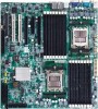
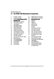
... 6. XGI Z9s VGA controller 7. Front USB cable connector 15. VGA port 29. RJ45 Lan Ports 32. North Bridge chip fan cable connector 39. English GA-3CESL3-RH Motherboard 1.2 GA-3CESL3-RH Motherboard Components 1. Winbond W83792G 11. Serial Port connector 12. Intrusion cable connector 41. Floppy cable connector 13 . IDE cable connector 17. PCI-E x16 Slot 24...
... 6. XGI Z9s VGA controller 7. Front USB cable connector 15. VGA port 29. RJ45 Lan Ports 32. North Bridge chip fan cable connector 39. English GA-3CESL3-RH Motherboard 1.2 GA-3CESL3-RH Motherboard Components 1. Winbond W83792G 11. Serial Port connector 12. Intrusion cable connector 41. Floppy cable connector 13 . IDE cable connector 17. PCI-E x16 Slot 24...
Manual
Page 7
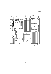
Introduction 39 40 78 9 44 18 6 45 19 20 21 22 23 30 28 32 31 29 25 27 26 11 12 41 5 4 38 14 3 13 1 42 43 36 15 10 35 2 34 37 33 17 16 24 7
Introduction 39 40 78 9 44 18 6 45 19 20 21 22 23 30 28 32 31 29 25 27 26 11 12 41 5 4 38 14 3 13 1 42 43 36 15 10 35 2 34 37 33 17 16 24 7
Manual
Page 8
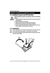
..., it will overheat without the heatsink and/or fan, resulting in one orientation. Remove the plastic covering on the processor before placing cooling fan. 4. English GA-3CESL3-RH Motherboard Chapter 2 Hardware Installation Process 2-1: Installing Processor and CPU Haet Sink Before installing the processor and cooling fan, adhere to the following cautions: 1. Please change...
..., it will overheat without the heatsink and/or fan, resulting in one orientation. Remove the plastic covering on the processor before placing cooling fan. 4. English GA-3CESL3-RH Motherboard Chapter 2 Hardware Installation Process 2-1: Installing Processor and CPU Haet Sink Before installing the processor and cooling fan, adhere to the following cautions: 1. Please change...
Manual
Page 9
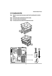
Step 3 Push down the clip to the processor socket. Step 2 Hook the other side of metal bracket into retention Module. 2-1-2: Installing Heat Sink Hardware Installation Process Step 1 Attach the heat sink clip to the locked position. Step 4 Connect processor fan can cable to the processor fan connector. 1 3 2 4 9 Hook the metal bracket into retention module.
Step 3 Push down the clip to the processor socket. Step 2 Hook the other side of metal bracket into retention Module. 2-1-2: Installing Heat Sink Hardware Installation Process Step 1 Attach the heat sink clip to the locked position. Step 4 Connect processor fan can cable to the processor fan connector. 1 3 2 4 9 Hook the metal bracket into retention module.
Manual
Page 10
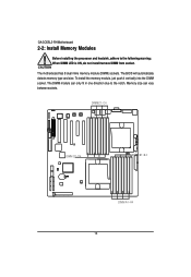
To install the memory module, just push it vertically into the DIMM socket .The DIMM module can vary between sockets. Memory size can only fit in one direction due to the following warning: When DIMM LED is ON, do not install/remove DIMM from socket. The BIOS will automatically detects memory type and size. The motherboard has 8 dual inline memory module (DIMM) sockets. English GA-3CESL3-RH Motherboard 2-2: Install Memory Modules Before installing the processor and heatsink, adhere to the notch. DIMMC1~C4 DIMM D1~D4 DIMM B1~B4 DIMM A1~A4 10
To install the memory module, just push it vertically into the DIMM socket .The DIMM module can vary between sockets. Memory size can only fit in one direction due to the following warning: When DIMM LED is ON, do not install/remove DIMM from socket. The BIOS will automatically detects memory type and size. The motherboard has 8 dual inline memory module (DIMM) sockets. English GA-3CESL3-RH Motherboard 2-2: Install Memory Modules Before installing the processor and heatsink, adhere to the notch. DIMMC1~C4 DIMM D1~D4 DIMM B1~B4 DIMM A1~A4 10
Manual
Page 11
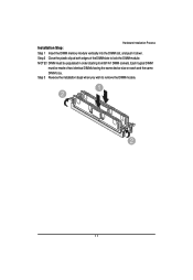
DIMM must be populated in order starting from B1/A1 DIMM sockets. Step 2 Close the plastic clip at both edges of two identical DIMMs having the same device size on each and the same DIMM size. Each logical DIMM must be made of theDIMM slots to remove the DIMM module. 1 2 2 11 Step 3 Reverse the installation steps when you wish to lock the DIMM module. Hardware Installation Process Installation Step: Step 1 Insert the DIMM memory module vertically into the DIMM slot, and push it down. NOTE!!
DIMM must be populated in order starting from B1/A1 DIMM sockets. Step 2 Close the plastic clip at both edges of two identical DIMMs having the same device size on each and the same DIMM size. Each logical DIMM must be made of theDIMM slots to remove the DIMM module. 1 2 2 11 Step 3 Reverse the installation steps when you wish to lock the DIMM module. Hardware Installation Process Installation Step: Step 1 Insert the DIMM memory module vertically into the DIMM slot, and push it down. NOTE!!
Manual
Page 12
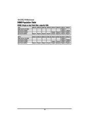
capacity 4GB. English GA-3CESL3-RH Motherboard DIMM Population Table DIMM: Single or dual Rank Max. CPU1 Single Channel (One DIMM) Dual Channel (2 DIMMs) Dual Channel (4 DIMMs) Dual Channel (8DIMMs) DIMM_A4 ...
capacity 4GB. English GA-3CESL3-RH Motherboard DIMM Population Table DIMM: Single or dual Rank Max. CPU1 Single Channel (One DIMM) Dual Channel (2 DIMMs) Dual Channel (4 DIMMs) Dual Channel (8DIMMs) DIMM_A4 ...
Manual
Page 13
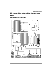
Hardware Installation Process 2-3: Connect ribbon cables, cabinet wires, and power supply 2-3-1 : I/O Back Panel Introduction 13
Hardware Installation Process 2-3: Connect ribbon cables, cabinet wires, and power supply 2-3-1 : I/O Back Panel Introduction 13
Manual
Page 14
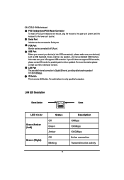
... Description 10Mbps 100Mbps 1000Mbps Active connection Transmit/receive activtiy 14 ID Switch This is Gigabit Ethernet, providing data transfer speeds of 10/100/1000Mbps. English GA-3CESL3-RH Motherboard PS/2 Keyboard and PS/2 Mouse Connector To install a PS/2 port keyboard and mouse, plug the mouse to the upper port (green) and the keyboard...
... Description 10Mbps 100Mbps 1000Mbps Active connection Transmit/receive activtiy 14 ID Switch This is Gigabit Ethernet, providing data transfer speeds of 10/100/1000Mbps. English GA-3CESL3-RH Motherboard PS/2 Keyboard and PS/2 Mouse Connector To install a PS/2 port keyboard and mouse, plug the mouse to the upper port (green) and the keyboard...
Manual
Page 15
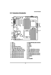
IDE1 (IDE cable connector) 5. SATA1 (SATA data cable connector) 10. SATA3 (SATA data cable connector) 12. CPU2_FAN (CPU2 fan connector) 20. SYS_FAN2 (System fan connector) 23. CLR_CMOS1 15 FDD1 (Floppy cable connector) 6. F_USB1 (Front USB cable connector) 7. F_USB2 (Internal USB cable connector) 8. SATA2 (SATA data cable connector) 11. SATA5 (SATA data cable connector) 14. GBT_FP1 17. SYS_FAN1 (System fan connector) 22. ATX_L1 2. ATX_12V2 4. MCP55_FAN (NB fan connector) 21. PS1 18. JP1 25. SATA0 (SATA data cable connector) 9. F_Panel1 16. COMB1 15. ...
IDE1 (IDE cable connector) 5. SATA1 (SATA data cable connector) 10. SATA3 (SATA data cable connector) 12. CPU2_FAN (CPU2 fan connector) 20. SYS_FAN2 (System fan connector) 23. CLR_CMOS1 15 FDD1 (Floppy cable connector) 6. F_USB1 (Front USB cable connector) 7. F_USB2 (Internal USB cable connector) 8. SATA2 (SATA data cable connector) 11. SATA5 (SATA data cable connector) 14. GBT_FP1 17. SYS_FAN1 (System fan connector) 22. ATX_L1 2. ATX_12V2 4. MCP55_FAN (NB fan connector) 21. PS1 18. JP1 25. SATA0 (SATA data cable connector) 9. F_Panel1 16. COMB1 15. ...
Manual
Page 16
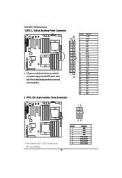
English GA-3CESL3-RH Motherboard 1) ATX_L1 (24-pin Auxiliary Power Connector) 24 12 AC power cord should only be connected to your power supply unit after ATX power cable ...
English GA-3CESL3-RH Motherboard 1) ATX_L1 (24-pin Auxiliary Power Connector) 24 12 AC power cord should only be connected to your power supply unit after ATX power cable ...
Manual
Page 17
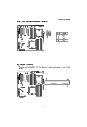
The red stripe of the ribbon cable must be the same side with the Pin1. 39 40 1 2 17 3 ) ATX_12V2 (4-pin Auxiliary Power Connector) Connector Introduction 13 24 Pin No. 1 2 3 4 Definition GND GND +12V +12V 4 ) IDE (IDE Connector) Please connect first harddisk to IDE1.
The red stripe of the ribbon cable must be the same side with the Pin1. 39 40 1 2 17 3 ) ATX_12V2 (4-pin Auxiliary Power Connector) Connector Introduction 13 24 Pin No. 1 2 3 4 Definition GND GND +12V +12V 4 ) IDE (IDE Connector) Please connect first harddisk to IDE1.
Manual
Page 18
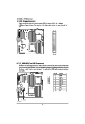
... pin assignment carefully while you connect the front USB cable, incorrect connection between the cable and connector will make the device unable to FDD. English GA-3CESL3-RH Motherboard 5 ) FDD (Floppy Connector) Please connect the floppy drive ribbon cables to work or even damage it. For optional front USB cable, please contact your...
... pin assignment carefully while you connect the front USB cable, incorrect connection between the cable and connector will make the device unable to FDD. English GA-3CESL3-RH Motherboard 5 ) FDD (Floppy Connector) Please connect the floppy drive ribbon cables to work or even damage it. For optional front USB cable, please contact your...
Manual
Page 19
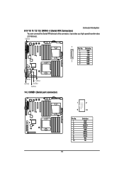
SATA0 1 Pin No. Definition 1 GND 2 TXP 3 TXN 4 GND 5 RXN 7 6 RXP 7 GND SATA4 SATA1 SATA3 SATA2 SATA5 14 ) COMB1 (Serial port connector) 1 2 9 10 Pin No. 1 2 3 4 5 6 7 8 9 10 Definition DCDSIN2 SOUT2 DTR2GND DSR2RTS2CTS2RI2NC 19 Connector Introduction 8/ 9/ 10/ 11/ 12/ 13 ) SATA 0~5 (Serial ATA Connectors) You can connect the Serial ATA device to this connector, it provides you high speed transfer rates (3.0 Gb/sec).
SATA0 1 Pin No. Definition 1 GND 2 TXP 3 TXN 4 GND 5 RXN 7 6 RXP 7 GND SATA4 SATA1 SATA3 SATA2 SATA5 14 ) COMB1 (Serial port connector) 1 2 9 10 Pin No. 1 2 3 4 5 6 7 8 9 10 Definition DCDSIN2 SOUT2 DTR2GND DSR2RTS2CTS2RI2NC 19 Connector Introduction 8/ 9/ 10/ 11/ 12/ 13 ) SATA 0~5 (Serial ATA Connectors) You can connect the Serial ATA device to this connector, it provides you high speed transfer rates (3.0 Gb/sec).
Manual
Page 20
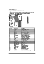
... Clock ID Switch Signal cathode(-) Chassis intrusion Signal ID Switch Ground LAN2 access LED Signal NMI Switch cathode(-) LAN2 linked LED Signal cathode(-) 20 English GA-3CESL3-RH Motherboard 15 ) F_Panel (2X12 Pins Front Panel connector) Please connect the power LED, PC speaker, reset switch and power switch of your chassis front panel...
... Clock ID Switch Signal cathode(-) Chassis intrusion Signal ID Switch Ground LAN2 access LED Signal NMI Switch cathode(-) LAN2 linked LED Signal cathode(-) 20 English GA-3CESL3-RH Motherboard 15 ) F_Panel (2X12 Pins Front Panel connector) Please connect the power LED, PC speaker, reset switch and power switch of your chassis front panel...