
User Manual
Page 1
GA-2CEWH AMD Socket 940 Dual Processor Motherboard USER'S MANUAL AMD Opteron™ Socket 940 Dual Processor Motherboard Rev. 1003
GA-2CEWH AMD Socket 940 Dual Processor Motherboard USER'S MANUAL AMD Opteron™ Socket 940 Dual Processor Motherboard Rev. 1003

User Manual
Page 2
... Content Item Checklist 4 WARNING 4 Chapter 1 Introduction 5 Summary of Features 5 GA-2CEWH Motherboard Layout 7 Chapter 2 Hardware Installation Process 9 Step 1: Installing Processor and CPU Cooling Fan 10 Step1-1: Installing CPU 10 Step1-2: Installing Cooling Fan 12 Step 2: Install memory ...
... Content Item Checklist 4 WARNING 4 Chapter 1 Introduction 5 Summary of Features 5 GA-2CEWH Motherboard Layout 7 Chapter 2 Hardware Installation Process 9 Step 1: Installing Processor and CPU Cooling Fan 10 Step1-1: Installing CPU 10 Step1-2: Installing Cooling Fan 12 Step 2: Install memory ...
User Manual
Page 4
.... Sometimes you can still attach the spacers to attach the spacers, do not have one, touch both of your hands). The GA-2CEWH motherboard ; SATA Cable x 4 ; GA-2CEWH user's manual ; Use a grounded wrist strap before you do not become alarmed you work on your computer when working on the... or cause board malfunctioning. 4 In this way you may need to use the plastic springs to the base without worrying about short circuits. GA-2CEWH Motherboard Item Checklist ; Be careful, don't let the screw contact any printed circuit write or parts on the bag that the ATX power supply...
.... Sometimes you can still attach the spacers to attach the spacers, do not have one, touch both of your hands). The GA-2CEWH motherboard ; SATA Cable x 4 ; GA-2CEWH user's manual ; Use a grounded wrist strap before you do not become alarmed you work on your computer when working on the... or cause board malfunctioning. 4 In this way you may need to use the plastic springs to the base without worrying about short circuits. GA-2CEWH Motherboard Item Checklist ; Be careful, don't let the screw contact any printed circuit write or parts on the bag that the ATX power supply...
User Manual
Page 5
...-performance PCI-X bus bridges, interated with PIO, Bus Master (ATA133) operation modes. 5 Chapter 1 Introduction Introduction Summary of operating at 400, 800, 1200, and 1600 MT/s. Motherboard GA-2CEWH Motherboard CPU Support Dual Opteron processors (Sledge Hammer) The HyperTransport link of the AMD Opteron processor is capable of Features Form Factor 30.4cm x 33.0cm...
...-performance PCI-X bus bridges, interated with PIO, Bus Master (ATA133) operation modes. 5 Chapter 1 Introduction Introduction Summary of operating at 400, 800, 1200, and 1600 MT/s. Motherboard GA-2CEWH Motherboard CPU Support Dual Opteron processors (Sledge Hammer) The HyperTransport link of the AMD Opteron processor is capable of Features Form Factor 30.4cm x 33.0cm...
User Manual
Page 6
GA-2CEWH Motherboard On-Board Peripherals RAID Supported Hardware Monitor Power Managerment Features IEEE1394A Audio On-Board LAN PS/2 Connector BIOS Additional Features 1 Floppy port supports 2 FDD with ...
GA-2CEWH Motherboard On-Board Peripherals RAID Supported Hardware Monitor Power Managerment Features IEEE1394A Audio On-Board LAN PS/2 Connector BIOS Additional Features 1 Floppy port supports 2 FDD with ...
User Manual
Page 7
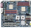
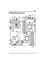
Introduction GA-2CEWH Motherboard Layout Y Z1 2 18 19 20 21 2223 24 25 F 6 16 W 10 11 12 13 14 G 15 X V H U 7 27 B 26 8 C 4 9 E D S R Q T KI J P 5 LO N M A 3 17 7
Introduction GA-2CEWH Motherboard Layout Y Z1 2 18 19 20 21 2223 24 25 F 6 16 W 10 11 12 13 14 G 15 X V H U 7 27 B 26 8 C 4 9 E D S R Q T KI J P 5 LO N M A 3 17 7
User Manual
Page 8
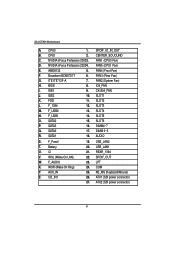
... power connector) 27. CPU1 2. NVIDIA nForce Profession 22204. ITE IT8712F-A 7. IDE1 9. SATA3 16. AUDIO S. REAR_1394 V. KB_MS (Keyboard/Mouse) Z. SLOT5 O. SLOT6 P. DIMM 0~3 R. CI 21. AUX_IN 25. GA-2CEWH Motherboard A. CPU0 1. SPDIF_IO_IN_OUT B. BIOS 8. DIMM4~7 Q. FAN4 (Front Fan) F. FAN3 (Rear Fan) G. F_AUDIO 23. SLOT3 M. SPDIF_OUT W. COM Y. NVIDIA nForce Profession 20503. FAN5 (CPU1 Fan) E. Broadcom BCM5751T 6. CK...
... power connector) 27. CPU1 2. NVIDIA nForce Profession 22204. ITE IT8712F-A 7. IDE1 9. SATA3 16. AUDIO S. REAR_1394 V. KB_MS (Keyboard/Mouse) Z. SLOT5 O. SLOT6 P. DIMM 0~3 R. CI 21. AUX_IN 25. GA-2CEWH Motherboard A. CPU0 1. SPDIF_IO_IN_OUT B. BIOS 8. DIMM4~7 Q. FAN4 (Front Fan) F. FAN3 (Rear Fan) G. F_AUDIO 23. SLOT3 M. SPDIF_OUT W. COM Y. NVIDIA nForce Profession 20503. FAN5 (CPU1 Fan) E. Broadcom BCM5751T 6. CK...
User Manual
Page 10
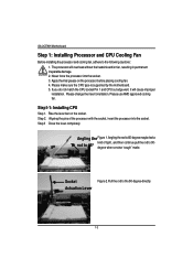
... Figure 1.Angling the rod to 65-degree maybe feel a rod to 650 kind of the processor with the socket, insert the processor into the socket. 3. GA-2CEWH Motherboard Step 1: Installing Processor and CPU Cooling Fan Before installing the processor and cooling fan, adhere to the following cautions: 1. Please change the insert orientation. If...
... Figure 1.Angling the rod to 65-degree maybe feel a rod to 650 kind of the processor with the socket, insert the processor into the socket. 3. GA-2CEWH Motherboard Step 1: Installing Processor and CPU Cooling Fan Before installing the processor and cooling fan, adhere to the following cautions: 1. Please change the insert orientation. If...
User Manual
Page 12
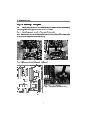
Step 2. Figure 5&6 Alignment of cooling fan will provide the best performance for heat releasing. Align the heatsink assembly with the support frame mating with Standoffs Figure 7 Connecting CPU FAN connector 12 Note: ** We recommend you to the processor fan connector. Coonect the processor fan cable to buy the kind of cooling fan which is shown in Figure 5&6. Attach th cooling fan clip to the processor scoket. This type of Heatsink Assembly with the backer plate standoffs as shown in Figure 8. GA-2CEWH Motherboard Step1-2: Installing Cooling Fan Step 1.
Step 2. Figure 5&6 Alignment of cooling fan will provide the best performance for heat releasing. Align the heatsink assembly with the support frame mating with Standoffs Figure 7 Connecting CPU FAN connector 12 Note: ** We recommend you to the processor fan connector. Coonect the processor fan cable to buy the kind of cooling fan which is shown in Figure 5&6. Attach th cooling fan clip to the processor scoket. This type of Heatsink Assembly with the backer plate standoffs as shown in Figure 8. GA-2CEWH Motherboard Step1-2: Installing Cooling Fan Step 1.

User Manual
Page 13
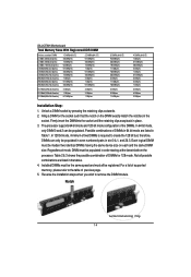
The BIOS will cause improper installation. Memory size can only fit in one notches. Wrong orientation will automatically detects memory type and size. The motherboard has 8 dual inline memory module (DIMM) sockets. To install the memory module, just push it vertically into the DIMM socket .The DIMM module can vary ...
The BIOS will cause improper installation. Memory size can only fit in one notches. Wrong orientation will automatically detects memory type and size. The motherboard has 8 dual inline memory module (DIMM) sockets. To install the memory module, just push it vertically into the DIMM socket .The DIMM module can vary ...
User Manual
Page 14
GA-2CEWH Motherboard Total Memory Sizes With Registered DDR DIMM Devices used on the DIMM exactly match the notches in place. 3. Unlock a DIMM socket by pressing the retaining ...
GA-2CEWH Motherboard Total Memory Sizes With Registered DDR DIMM Devices used on the DIMM exactly match the notches in place. 3. Unlock a DIMM socket by pressing the retaining ...
User Manual
Page 16
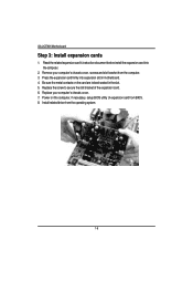
... card firmly into the computer. 2. Replace your computer's chassis cover, screws and slot bracket from the computer. 3. Power on the card are indeed seated in motherboard. 4. GA-2CEWH Motherboard Step 3: Install expansion cards 1. Be sure the metal contacts on the computer, if necessary, setup BIOS utility of the expansion card. 6. Install related driver from...
... card firmly into the computer. 2. Replace your computer's chassis cover, screws and slot bracket from the computer. 3. Power on the card are indeed seated in motherboard. 4. GA-2CEWH Motherboard Step 3: Install expansion cards 1. Be sure the metal contacts on the computer, if necessary, setup BIOS utility of the expansion card. 6. Install related driver from...
User Manual
Page 18
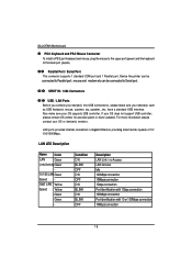
... LAN Green Speed - For more information please contact your OS does not support USB controller, please contact OS vendor for possible patch or driver updated. GA-2CEWH Motherboard PS/2 Keyboard and PS/2 Mouse Connector To install a PS/2 port keyboard and mouse, plug the mouse to the upper port (green) and the keyboard to...
... LAN Green Speed - For more information please contact your OS does not support USB controller, please contact OS vendor for possible patch or driver updated. GA-2CEWH Motherboard PS/2 Keyboard and PS/2 Mouse Connector To install a PS/2 port keyboard and mouse, plug the mouse to the upper port (green) and the keyboard to...

User Manual
Page 20
GA-2CEWH Motherboard Step4-2: Connectors Introduction R ST U 3 P O N L Y Z M V 2 K J I EC H D GF5 Q 6 20 4 1 B A X W
GA-2CEWH Motherboard Step4-2: Connectors Introduction R ST U 3 P O N L Y Z M V 2 K J I EC H D GF5 Q 6 20 4 1 B A X W
User Manual
Page 22
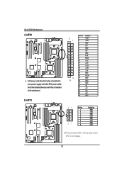
GA-2CEWH Motherboard A ) ATX2 ¾ AC power cord should only be connected to your power supply unit after ATX power cable and other related devices are firmly connected to the mainboard. B ) ATX1 13 1 12 24 PIN No. 1 2 3 4 5 6 7 8 9 10 11 12 13 14 15 16 17 18 19 20 21 22 23 24 Definition +3.3V +3.3V GND +5V GND +5V GND POK 5VSB +12V +12V +3.3V +3.3V -12V GND PSON GND GND GND -5V +5V +5V +5V GND 87 21 Pin No. 1 2 3 4 5 6 7 8 Definition GND +12v GND +12V GND +12V GND +12V ¾This connector (ATX +12V) is used only for CPU Core Voltage. 22
GA-2CEWH Motherboard A ) ATX2 ¾ AC power cord should only be connected to your power supply unit after ATX power cable and other related devices are firmly connected to the mainboard. B ) ATX1 13 1 12 24 PIN No. 1 2 3 4 5 6 7 8 9 10 11 12 13 14 15 16 17 18 19 20 21 22 23 24 Definition +3.3V +3.3V GND +5V GND +5V GND POK 5VSB +12V +12V +3.3V +3.3V -12V GND PSON GND GND GND -5V +5V +5V +5V GND 87 21 Pin No. 1 2 3 4 5 6 7 8 Definition GND +12v GND +12V GND +12V GND +12V ¾This connector (ATX +12V) is used only for CPU Core Voltage. 22
User Manual
Page 24
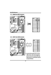
Definition 1 Do Not Connect 2 Do Not Connect 11 13 4 Power Power 5 Data- 12 26 Data- 7 Data+ 8 Data+ 9 GND 10 GND 11 Key 12 NC G ) F_ USB1 (Front USB Connector) 10 2 91 PIN No. 1 2 3 4 5 6 7 8 9 10 Definition Power Power DataDataData+ Data+ GND GND Key NC ¾ Be careful with the polarity of the front panel USB connector. Check the pin assignment while you connect the front panel USB cable. Please contact your nearest dealer for optional front panel USB cable. 24 GA-2CEWH Motherboard F ) F_ USB2 (Front USB Connector) PIN No.
Definition 1 Do Not Connect 2 Do Not Connect 11 13 4 Power Power 5 Data- 12 26 Data- 7 Data+ 8 Data+ 9 GND 10 GND 11 Key 12 NC G ) F_ USB1 (Front USB Connector) 10 2 91 PIN No. 1 2 3 4 5 6 7 8 9 10 Definition Power Power DataDataData+ Data+ GND GND Key NC ¾ Be careful with the polarity of the front panel USB connector. Check the pin assignment while you connect the front panel USB cable. Please contact your nearest dealer for optional front panel USB cable. 24 GA-2CEWH Motherboard F ) F_ USB2 (Front USB Connector) PIN No.
User Manual
Page 26
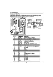
GA-2CEWH Motherboard M ) F_Panel1 (2X10 Pins) Please connect the power LED, PC speaker, reset switch and power switch etc of your chassis front panel to the front panel ...
GA-2CEWH Motherboard M ) F_Panel1 (2X10 Pins) Please connect the power LED, PC speaker, reset switch and power switch etc of your chassis front panel to the front panel ...
User Manual
Page 28
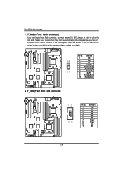
... have front audio connector. Also please make sure the pin assigment on the cable is the same as the pin assigment on the MB header. GA-2CEWH Motherboard P ) F_Audio (Front Audio connector) If you want to utilize the front audio header, your dealer. Pin No.
... have front audio connector. Also please make sure the pin assigment on the cable is the same as the pin assigment on the MB header. GA-2CEWH Motherboard P ) F_Audio (Front Audio connector) If you want to utilize the front audio header, your dealer. Pin No.

User Manual
Page 30
Use this feature only when your stereo system has digital input function. 65 21 SPDIF Pin No. 1 2 3 4 5 6 Definition P5V Pin Removed SPDIFO SPDIFI GND GND U ) SUR_CEN1 (Center Suround Connector) Please contact your nearest dealer for optional SUR_CEN cable. 65 Pin No. Definition 1 SURR_OUT_L 2 SURR_OUT_R 3 AUDGND 21 4 Pin Removed 5 CENTER_OUT 6 LFE_OUT 30 GA-2CEWH Motherboard T )SPDIF_IO (Red Connector) The SPDIF output is capable of providing digital audio to external speakers or compressed AC3 data to an external Dolby Digital Decoder.
Use this feature only when your stereo system has digital input function. 65 21 SPDIF Pin No. 1 2 3 4 5 6 Definition P5V Pin Removed SPDIFO SPDIFI GND GND U ) SUR_CEN1 (Center Suround Connector) Please contact your nearest dealer for optional SUR_CEN cable. 65 Pin No. Definition 1 SURR_OUT_L 2 SURR_OUT_R 3 AUDGND 21 4 Pin Removed 5 CENTER_OUT 6 LFE_OUT 30 GA-2CEWH Motherboard T )SPDIF_IO (Red Connector) The SPDIF output is capable of providing digital audio to external speakers or compressed AC3 data to an external Dolby Digital Decoder.
User Manual
Page 32
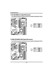
Pin No. Definition 1 GND 2 12V 3 1 Sense Z ) CK804_FAN (NVIDIA CK804 Chipset FAN connector) If you installed wrong direction, the Chip Fan will not work . Pin No. Sometimes will damage the Chip Fan. Definition 1 GND 2 12V 3 1 Sense 32 GA-2CEWH Motherboard Y ) IO4_FAN (NVIDIA IO-4 Chipset FAN connector) If you installed wrong direction, the Chip Fan will not work . Sometimes will damage the Chip Fan.
Pin No. Definition 1 GND 2 12V 3 1 Sense Z ) CK804_FAN (NVIDIA CK804 Chipset FAN connector) If you installed wrong direction, the Chip Fan will not work . Pin No. Sometimes will damage the Chip Fan. Definition 1 GND 2 12V 3 1 Sense 32 GA-2CEWH Motherboard Y ) IO4_FAN (NVIDIA IO-4 Chipset FAN connector) If you installed wrong direction, the Chip Fan will not work . Sometimes will damage the Chip Fan.


