Manual
Page 1
GA-2AIEL1-RH GA-2AIEL5-RH AMD® mini-ITX Motherboard USER'S MANUAL AMD® mini-ITX Motherboard Rev. 1001 * The WEEE marking on the product indicates this product must not be disposed of with user's other household waste and must be handed over to a designated collection point for the recycling of waste electrical and electronic equipment!! * The WEEE marking applies only in European Union's member states.
GA-2AIEL1-RH GA-2AIEL5-RH AMD® mini-ITX Motherboard USER'S MANUAL AMD® mini-ITX Motherboard Rev. 1001 * The WEEE marking on the product indicates this product must not be disposed of with user's other household waste and must be handed over to a designated collection point for the recycling of waste electrical and electronic equipment!! * The WEEE marking applies only in European Union's member states.
Manual
Page 2
...; For detailed product information and specifications, please carefully read or download the information you need. For more product details, please click onto Gigabyte's website at www.gigabyte.com.tw 2 GA-2AIEL1-RH/GA-2AIEL5-RH Motherboard Copyright © 2009 GIGA-BYTE TECHNOLOGY CO., LTD. The trademarks mentioned in the manual are subject to assist in any form...
...; For detailed product information and specifications, please carefully read or download the information you need. For more product details, please click onto Gigabyte's website at www.gigabyte.com.tw 2 GA-2AIEL1-RH/GA-2AIEL5-RH Motherboard Copyright © 2009 GIGA-BYTE TECHNOLOGY CO., LTD. The trademarks mentioned in the manual are subject to assist in any form...
Manual
Page 3
English Table of Contents Table of Content Item Checklist...4 Chapter 1 Introduction...5 1-1 Considerations Prior to Installation 5 1.2 Features Summary 6 1.3 Motherboard Components 8 Chapter 2 Hardware Installation Process 9 2-1: Install Memory Modules 9 2-2: I/O Back Panel Introduction 10 2-3: Connectors Introduction 14 2-4: Block Diagram 21 Chapter 3 BIOS Setup 22 3-1: Startup Screen 23 3-2: The Main Menu 24 3-3: Standard CMOS Features 26 3-4: Advanced BIOS Features 28 3-5: Integrated Peripherals 30 3-6: Power Management Setup 32 3-7: PC Health Status 34 3-8: Load Fail-...
English Table of Contents Table of Content Item Checklist...4 Chapter 1 Introduction...5 1-1 Considerations Prior to Installation 5 1.2 Features Summary 6 1.3 Motherboard Components 8 Chapter 2 Hardware Installation Process 9 2-1: Install Memory Modules 9 2-2: I/O Back Panel Introduction 10 2-3: Connectors Introduction 14 2-4: Block Diagram 21 Chapter 3 BIOS Setup 22 3-1: Startup Screen 23 3-2: The Main Menu 24 3-3: Standard CMOS Features 26 3-4: Advanced BIOS Features 28 3-5: Integrated Peripherals 30 3-6: Power Management Setup 32 3-7: PC Health Status 34 3-8: Load Fail-...
Manual
Page 4
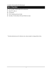
GA-2AIEL1-RH/GA-2AIEL5-RH Motherboard Item Checklist The GA-2AIEL1-RH/GA-2AIEL5-RH motherboard Serial ATA cable x 2 I/O Shield Kit CD for motherboard driver & utility GA-2AIEL1-RH/GA-2AIEL5-RH Quick Reference Guide * The items listed above are for reference only, and are subject to change without notice. 4
GA-2AIEL1-RH/GA-2AIEL5-RH Motherboard Item Checklist The GA-2AIEL1-RH/GA-2AIEL5-RH motherboard Serial ATA cable x 2 I/O Shield Kit CD for motherboard driver & utility GA-2AIEL1-RH/GA-2AIEL5-RH Quick Reference Guide * The items listed above are for reference only, and are subject to change without notice. 4

Manual
Page 5
... screws to come in the user manual. 3. Damage as a result of the motherboard or any metal leads or connectors. 3. Damage due to be an unofficial Gigabyte product. 5 Product determined to use of Non-Warranty 1. Please verify that all cables and power connectors are uncertain about any installation steps or have these...
... screws to come in the user manual. 3. Damage as a result of the motherboard or any metal leads or connectors. 3. Damage due to be an unofficial Gigabyte product. 5 Product determined to use of Non-Warranty 1. Please verify that all cables and power connectors are uncertain about any installation steps or have these...
Manual
Page 6
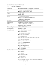
CPU K8 BGA 1.0GHz (GA-2AIEL1-RH) K8 BGA 1.5GHz (GA-2AIEL5-RH) Chipset AMD® 690E AMD® SB600 Memory 1 x DDR2 DIMM sockets Supports up to 2GB 533/667/800 memory Supports 1.... ports(COM) 4 x USB 2.0 port 1 x LAN RJ45 port 1 HD Audio jack (Line-out / MIC-in / Line-in) can configure 5.1 channel output by utility 6 GA-2AIEL1-RH/GA-2AIEL5-RH Motherboard 1.2 Features Summary Form Factor 170mm x 170mm Mini ITX form factor, 4 layers PCB.
CPU K8 BGA 1.0GHz (GA-2AIEL1-RH) K8 BGA 1.5GHz (GA-2AIEL5-RH) Chipset AMD® 690E AMD® SB600 Memory 1 x DDR2 DIMM sockets Supports up to 2GB 533/667/800 memory Supports 1.... ports(COM) 4 x USB 2.0 port 1 x LAN RJ45 port 1 HD Audio jack (Line-out / MIC-in / Line-in) can configure 5.1 channel output by utility 6 GA-2AIEL1-RH/GA-2AIEL5-RH Motherboard 1.2 Features Summary Form Factor 170mm x 170mm Mini ITX form factor, 4 layers PCB.

Manual
Page 7
Hardware Monitor On-Board LAN BIOS Additional Features Introduction Enhanced features with CPU Vcore, DDR2 1.8V , +3.3V, +12V value viewing System/CPU temperature value viewing CPU shutdown when overheat Realtek RTL8111C GbE coneroller Supports WOL Award BIOS on 8Mb SPI Flash ROM Supports S1, S3, S4, S5 under Windows Operating System Supports 4-pin Fan controller 7
Hardware Monitor On-Board LAN BIOS Additional Features Introduction Enhanced features with CPU Vcore, DDR2 1.8V , +3.3V, +12V value viewing System/CPU temperature value viewing CPU shutdown when overheat Realtek RTL8111C GbE coneroller Supports WOL Award BIOS on 8Mb SPI Flash ROM Supports S1, S3, S4, S5 under Windows Operating System Supports 4-pin Fan controller 7

Manual
Page 8
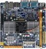
F_USB1 F_PANEL F_USB2 DIO_CON GA-2AIEL1-RH/GA-2AIEL5-RH Motherboard 1.3 Motherboard Components (GA-2AIEL1-RH/GA-2AIEL5-RH) SYS_FAN1 CF Card connector SATA 1 SATA 2 SATA 3 SATA 4 AMD SB600 ATX Power DDRll_1 CLR_CMOS1 BATTERY CPU AMD 690E ITE Super I/O LVDS_CON BLIGHT_CON1 COM2 VGA COM1 HDMI SPDIF out (OPTICAL) CPU_FAN1 COM4 COM3 PCI-Ex4 LAN USB Audio Jack F_AUDIO1 8
F_USB1 F_PANEL F_USB2 DIO_CON GA-2AIEL1-RH/GA-2AIEL5-RH Motherboard 1.3 Motherboard Components (GA-2AIEL1-RH/GA-2AIEL5-RH) SYS_FAN1 CF Card connector SATA 1 SATA 2 SATA 3 SATA 4 AMD SB600 ATX Power DDRll_1 CLR_CMOS1 BATTERY CPU AMD 690E ITE Super I/O LVDS_CON BLIGHT_CON1 COM2 VGA COM1 HDMI SPDIF out (OPTICAL) CPU_FAN1 COM4 COM3 PCI-Ex4 LAN USB Audio Jack F_AUDIO1 8
Manual
Page 9
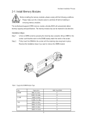
Step 2. The memory module only can be inserted in place. The motherboard supports DDR2 memory module, whereby BIOS will automatically detect memory capacity and specifications. Firmly insert the DIMMinto the socket until the retaining clips snap back in one direction. 2-1: Install Memory Modules Hardware Installation Process Before installing the memory modules, please comply with the following conditions: 1. Aling a DIMM on the socket such that the notch on the DIMM exactly match the notch in the socket. Reverse the installation steps if you want to remove the DIMM ...
Step 2. The memory module only can be inserted in place. The motherboard supports DDR2 memory module, whereby BIOS will automatically detect memory capacity and specifications. Firmly insert the DIMMinto the socket until the retaining clips snap back in one direction. 2-1: Install Memory Modules Hardware Installation Process Before installing the memory modules, please comply with the following conditions: 1. Aling a DIMM on the socket such that the notch on the DIMM exactly match the notch in the socket. Reverse the installation steps if you want to remove the DIMM ...
Manual
Page 10
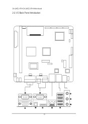
GA-2AIEL1-RH/GA-2AIEL5-RH Motherboard 2-2: I/O Back Panel Introduction 10
GA-2AIEL1-RH/GA-2AIEL5-RH Motherboard 2-2: I/O Back Panel Introduction 10

Manual
Page 11
The HDMI Technology can be connected to this port. have a standard USB interface. Hardware Installation Process Serial Port Modem can support a maximum resolution of 10/100/1000Mbps. Connect the HDMI audio/video device to serial port. If your OS or device(s) vendors. 11 For more information please contact your OS does not support USB controller,please contact OS vendor for providing digital audio to external speakers or compressed AC3 data to an external Dolby Digital Decoder via an optical cable. HDMI Port The HDMI (High-Definition Multimedia Interface) provides an all...
The HDMI Technology can be connected to this port. have a standard USB interface. Hardware Installation Process Serial Port Modem can support a maximum resolution of 10/100/1000Mbps. Connect the HDMI audio/video device to serial port. If your OS or device(s) vendors. 11 For more information please contact your OS does not support USB controller,please contact OS vendor for providing digital audio to external speakers or compressed AC3 data to an external Dolby Digital Decoder via an optical cable. HDMI Port The HDMI (High-Definition Multimedia Interface) provides an all...

Manual
Page 12
GA-2AIEL1-RH/GA-2AIEL5-RH Motherboard NOTE: After installing the HDMI device, make sure the default device for details.), and enter BIOS Setup, then set the Default device for sound ...
GA-2AIEL1-RH/GA-2AIEL5-RH Motherboard NOTE: After installing the HDMI device, make sure the default device for details.), and enter BIOS Setup, then set the Default device for sound ...

Manual
Page 13
Stereo speakers, earphone or front surround speakers can be connected to Line Out (Front Speaker Out) jack. Hardware Installation Process Line In The default Line In jack. Devices like CD-ROM, walkman etc. Microphone must be connected to Line In jack. Line Out (Front Speaker Out) The default Line Out (Front Speaker Out) jack. can be connected to MIC In jack. 13 MIC In The default MIC In jack.
Stereo speakers, earphone or front surround speakers can be connected to Line Out (Front Speaker Out) jack. Hardware Installation Process Line In The default Line In jack. Devices like CD-ROM, walkman etc. Microphone must be connected to Line In jack. Line Out (Front Speaker Out) The default Line Out (Front Speaker Out) jack. can be connected to MIC In jack. 13 MIC In The default MIC In jack.
Manual
Page 15
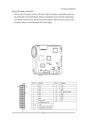
20-pin ATX power connectors Connector Introduction With the use of the power connector, the power supply can supply enough stable power to all components and devices are properly installed. Align the power connector with its proper location on the motherboard. Before connecting the power connector, please make sure that all the components on the motherboard and connect tightly. 10 20 1 11 Pin No. 1 2 3 4 5 6 7 8 9 10 + 11 12 3.3V 3.3V GND +5V GND +5V GND Power Good 5V SB(stand by +5V) 12V +12V(Only for 24-pin ATX) 3.3V(Only for 24-pin ATX) Pin No. 13 14 15 16 17 18 19 20 3.3V -...
20-pin ATX power connectors Connector Introduction With the use of the power connector, the power supply can supply enough stable power to all components and devices are properly installed. Align the power connector with its proper location on the motherboard. Before connecting the power connector, please make sure that all the components on the motherboard and connect tightly. 10 20 1 11 Pin No. 1 2 3 4 5 6 7 8 9 10 + 11 12 3.3V 3.3V GND +5V GND +5V GND Power Good 5V SB(stand by +5V) 12V +12V(Only for 24-pin ATX) 3.3V(Only for 24-pin ATX) Pin No. 13 14 15 16 17 18 19 20 3.3V -...
Manual
Page 16
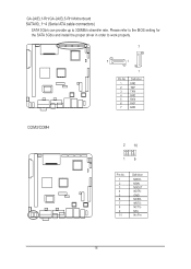
F_USB 7 F_1394 IR/CIR IR 7 1 1 COMB Pin No. 1 2 3 4 5 6 7 Definition GND TXP TXN GND RXN RXP GND COM3/COM4 F_USB SUR_CEN MODEM 2 10 COMB 19 Pin No. 1 2 3 4 Power 5 6 7 8 9 10 Definition NDCDNSIN NSOUT NDTRGND NDSRNRTSNCTSNRINo Pin SPDIF_IO 16 F2_1394 Please refer to the BIOS setting for the SATA 3Gb/s and install the proper driver in order to 300MB/s stransfer rate. GA-2AIEL1-RH/GA-2AIEL5-RH Motherboard SATAII0_1~4 (Serial ATA cable connectors) F_SAUADTIOA 3Gb/s can provide up to work properly.
F_USB 7 F_1394 IR/CIR IR 7 1 1 COMB Pin No. 1 2 3 4 5 6 7 Definition GND TXP TXN GND RXN RXP GND COM3/COM4 F_USB SUR_CEN MODEM 2 10 COMB 19 Pin No. 1 2 3 4 Power 5 6 7 8 9 10 Definition NDCDNSIN NSOUT NDTRGND NDSRNRTSNCTSNRINo Pin SPDIF_IO 16 F2_1394 Please refer to the BIOS setting for the SATA 3Gb/s and install the proper driver in order to 300MB/s stransfer rate. GA-2AIEL1-RH/GA-2AIEL5-RH Motherboard SATAII0_1~4 (Serial ATA cable connectors) F_SAUADTIOA 3Gb/s can provide up to work properly.
Manual
Page 17
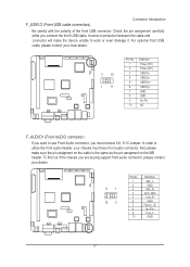
Check the pin assignment carefully while you connect the front USB cable, incorrect connection between the cable and connector will make sure the pin assigment on the cable is the same as the pin assigment on the MB header. In order to use Front Audio connector, you want to CLR_PWD utilize the front audio header, your chassis must remove 5-6, 9-10 Jumper. F_PANEL F1_1394 F_PANEL F_AUDIO 91 SPDIF_IO 10 2 Pin No. 1 2 3 4 5 6 7 8 9 10 Definition MIC_L GND MIC_R -ACZ_DEC Line_R F2_1394 GND Faudio_JD No Pin FL_iUneS_BL F_G1N39D4 GAME F_PANEL IR/CIR 17 IR...
Check the pin assignment carefully while you connect the front USB cable, incorrect connection between the cable and connector will make sure the pin assigment on the cable is the same as the pin assigment on the MB header. In order to use Front Audio connector, you want to CLR_PWD utilize the front audio header, your chassis must remove 5-6, 9-10 Jumper. F_PANEL F1_1394 F_PANEL F_AUDIO 91 SPDIF_IO 10 2 Pin No. 1 2 3 4 5 6 7 8 9 10 Definition MIC_L GND MIC_R -ACZ_DEC Line_R F2_1394 GND Faudio_JD No Pin FL_iUneS_BL F_G1N39D4 GAME F_PANEL IR/CIR 17 IR...

Manual
Page 18
GA-2AIEL1-RH/GA-2AIEL5-RH Motherboard LVDS connector LVDS stands for Low-voltage differential signaling, which uses high-speed analog circuit techniques to provide multigigabit data transfers on copper interconnects ...
GA-2AIEL1-RH/GA-2AIEL5-RH Motherboard LVDS connector LVDS stands for Low-voltage differential signaling, which uses high-speed analog circuit techniques to provide multigigabit data transfers on copper interconnects ...
Manual
Page 19
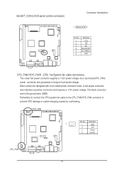
The black connector wire is the ground wire (GND). Remember to connect the CPU/system fan cable to the CPU_FAN/SYS_FAN connector to prevent CPU damage or system hanging caused by overheating. Most coolers are designed with color-coded power connector wires. SYS_FAN Pin No. A red power connector wire indicates a positive connection and requires a +12V power voltage. Definition 1 1 GND 2 12V 3 Sense 4 Control CPU_FAN 19 BLIGHT_CON (LVDS panel control connector) Connector Introduction 1 6 Pin No. 1 2 3 4 5 6 Definition +12V +5V NC BL ...
The black connector wire is the ground wire (GND). Remember to connect the CPU/system fan cable to the CPU_FAN/SYS_FAN connector to prevent CPU damage or system hanging caused by overheating. Most coolers are designed with color-coded power connector wires. SYS_FAN Pin No. A red power connector wire indicates a positive connection and requires a +12V power voltage. Definition 1 1 GND 2 12V 3 Sense 4 Control CPU_FAN 19 BLIGHT_CON (LVDS panel control connector) Connector Introduction 1 6 Pin No. 1 2 3 4 5 6 Definition +12V +5V NC BL ...
Manual
Page 20
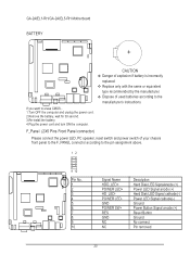
... connect 10. GND Ground 6. GND Ground 9. Signal Name Description 1. POWER LED+ Power LED Signal anode (+) 3. Hard Disk LED Signal cathode(-) 4. Power LED Signal cathode(-) 5. GA-2AIEL1-RH/GA-2AIEL5-RH Motherboard BATTERY F_USB F_1394 Serial ATA F1_1394 CAUTION Danger of used batteries according to the pin assignment above. SPDIF Replace only with the...
... connect 10. GND Ground 6. GND Ground 9. Signal Name Description 1. POWER LED+ Power LED Signal anode (+) 3. Hard Disk LED Signal cathode(-) 4. Power LED Signal cathode(-) 5. GA-2AIEL1-RH/GA-2AIEL5-RH Motherboard BATTERY F_USB F_1394 Serial ATA F1_1394 CAUTION Danger of used batteries according to the pin assignment above. SPDIF Replace only with the...
Manual
Page 22
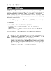
...that you not alter the default settings (unless you not flash the BIOS. For instructions on using the current version of BIOS, it with caution. GA-2AIEL1-RH/GA-2AIEL5-RH Motherboard Chapter 3 BIOS Setup BIOS (Basic Input and Output System) records hardware parameters of the BIOS Setup program. Inadequate BIOS flashing may result in... upgrade or back up BIOS without entering the operating system. • @BIOS is turned on the motherboard. To upgrade the BIOS, use either the GIGABYTE Q-Flash or @BIOS utility. • Q-Flash allows the user to activate certain system features.
...that you not alter the default settings (unless you not flash the BIOS. For instructions on using the current version of BIOS, it with caution. GA-2AIEL1-RH/GA-2AIEL5-RH Motherboard Chapter 3 BIOS Setup BIOS (Basic Input and Output System) records hardware parameters of the BIOS Setup program. Inadequate BIOS flashing may result in... upgrade or back up BIOS without entering the operating system. • @BIOS is turned on the motherboard. To upgrade the BIOS, use either the GIGABYTE Q-Flash or @BIOS utility. • Q-Flash allows the user to activate certain system features.