User Manual
Page 3
... are legally registered to their respective owners. For product-related information, check on our website at: http://www.gigabyte.com Identifying Your Motherboard Revision The revision number on your motherboard revision before updating motherboard BIOS, drivers, or when looking for technical information. Example: For example, "REV: 1.0" means the revision of the product...
... are legally registered to their respective owners. For product-related information, check on our website at: http://www.gigabyte.com Identifying Your Motherboard Revision The revision number on your motherboard revision before updating motherboard BIOS, drivers, or when looking for technical information. Example: For example, "REV: 1.0" means the revision of the product...
User Manual
Page 4
Table of Contents Box Contents...6 Optional Items...6 G1.Sniper M3 Motherboard Layout 7 G1.Sniper M3 Motherboard Block Diagram 8 Chapter 1 Hardware Installation 9 1-1 Installation Precautions 9 1-2 Product Specifications 10 1-3 Installing the CPU and CPU ... up AMD CrossFireX™/NVIDIA SLI Configuration 19 1-7 Back Panel Connectors 20 1-8 Internal Connectors 23 Chapter 2 BIOS Setup 31 2-1 Startup Screen 32 2-2 The Main Menu 33 2-3 M.I.T...35 2-4 System...45 2-5 BIOS Features 46 2-6 Peripherals...48 2-7 Power Management 51 2-8 Save & Exit...53 Chapter 3 Drivers Installation 55...
Table of Contents Box Contents...6 Optional Items...6 G1.Sniper M3 Motherboard Layout 7 G1.Sniper M3 Motherboard Block Diagram 8 Chapter 1 Hardware Installation 9 1-1 Installation Precautions 9 1-2 Product Specifications 10 1-3 Installing the CPU and CPU ... up AMD CrossFireX™/NVIDIA SLI Configuration 19 1-7 Back Panel Connectors 20 1-8 Internal Connectors 23 Chapter 2 BIOS Setup 31 2-1 Startup Screen 32 2-2 The Main Menu 33 2-3 M.I.T...35 2-4 System...45 2-5 BIOS Features 46 2-6 Peripherals...48 2-7 Power Management 51 2-8 Save & Exit...53 Chapter 3 Drivers Installation 55...
User Manual
Page 5
3-4 Contact...57 3-5 System...57 3-6 Download Center 58 3-7 New Program 58 Chapter 4 Unique Features 59 4-1 Xpress Recovery2 59 4-2 BIOS Update Utilities 62 4-2-1 Updating the BIOS with the Q-Flash Utility 62 4-2-2 Updating the BIOS with the @BIOS Utility 65 4-3 EasyTune 6...66 4-4 Q-Share...67 4-5 eXtreme Hard Drive (X.H.D 68 4-6 Auto Green...69 4-7 Intel Rapid Start Technology 70 4-8 Intel Smart...
3-4 Contact...57 3-5 System...57 3-6 Download Center 58 3-7 New Program 58 Chapter 4 Unique Features 59 4-1 Xpress Recovery2 59 4-2 BIOS Update Utilities 62 4-2-1 Updating the BIOS with the Q-Flash Utility 62 4-2-2 Updating the BIOS with the @BIOS Utility 65 4-3 EasyTune 6...66 4-4 Q-Share...67 4-5 eXtreme Hard Drive (X.H.D 68 4-6 Auto Green...69 4-7 Intel Rapid Start Technology 70 4-8 Intel Smart...
User Manual
Page 8
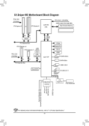
G1.Sniper M3 Motherboard Block Diagram PCIe CLK (100 MHz) 1 PCI Express x16 or 2 PCI Express x8 LGA1155 CPU CPU CLK+/- (100 MHz) DDR3 1600/1333/1066 MHz ... 1 PCI Express x4 LAN 1 PCI Express x1 RJ45 PCIe CLK (100 MHz) Intel GbE LAN x4 x1 x1 PCI Express Bus Intel® Z77 Dual BIOS DMI 2.0 FDI D-Sub DisplayPort DVI-D HDMI 4 SATA 3Gb/s 2 SATA 6Gb/s 4 USB 3.0/2.0 10 USB 2.0/1.1 LPC Bus CREATIVE CA0132 iTE Super I/O PS/2 KB/Mouse Surround Speaker Out...
G1.Sniper M3 Motherboard Block Diagram PCIe CLK (100 MHz) 1 PCI Express x16 or 2 PCI Express x8 LGA1155 CPU CPU CLK+/- (100 MHz) DDR3 1600/1333/1066 MHz ... 1 PCI Express x4 LAN 1 PCI Express x1 RJ45 PCIe CLK (100 MHz) Intel GbE LAN x4 x1 x1 PCI Express Bus Intel® Z77 Dual BIOS DMI 2.0 FDI D-Sub DisplayPort DVI-D HDMI 4 SATA 3Gb/s 2 SATA 6Gb/s 4 USB 3.0/2.0 10 USB 2.0/1.1 LPC Bus CREATIVE CA0132 iTE Super I/O PS/2 KB/Mouse Surround Speaker Out...
User Manual
Page 12
... 12 - I/O Controller ŠŠ iTE I/O Controller Chip Hardware ŠŠ Monitor ŠŠ ŠŠ ŠŠ ŠŠ Š Š BIOS ŠŠ ŠŠ ŠŠ ŠŠ Unique Features ŠŠ ŠŠ ŠŠ ŠŠ ŠŠ ŠŠ...the CPU/system cooler you install. 2 x 64 Mbit flash Use of licensed AMI EFI BIOS Support for DualBIOS™ PnP 1.0a, DMI 2.0, SM BIOS 2.6, ACPI 2.0a Support for @BIOS Support for Q-Flash Support for Xpress Install Support for Xpress Recovery2 Support for Microsoft® ...
... 12 - I/O Controller ŠŠ iTE I/O Controller Chip Hardware ŠŠ Monitor ŠŠ ŠŠ ŠŠ ŠŠ Š Š BIOS ŠŠ ŠŠ ŠŠ ŠŠ Unique Features ŠŠ ŠŠ ŠŠ ŠŠ ŠŠ ŠŠ...the CPU/system cooler you install. 2 x 64 Mbit flash Use of licensed AMI EFI BIOS Support for DualBIOS™ PnP 1.0a, DMI 2.0, SM BIOS 2.6, ACPI 2.0a Support for @BIOS Support for Q-Flash Support for Xpress Install Support for Xpress Recovery2 Support for Microsoft® ...
User Manual
Page 16
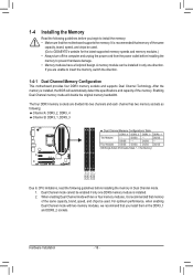
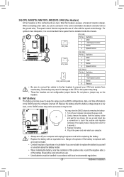
... enabled if only one direction. For optimum performance, when enabling Dual Channel mode with two or four memory modules, it is installed, the BIOS will double the original memory bandwidth. The four DDR3 memory sockets are unable to prevent hardware damage. •• Memory modules have a ...Dual Channel Technology. Dual Channel mode cannot be used . (Go to install the memory: •• Make sure that you begin to GIGABYTE's website for the latest supported memory speeds and memory modules.) •• Always turn off the computer and unplug the power cord from the...
... enabled if only one direction. For optimum performance, when enabling Dual Channel mode with two or four memory modules, it is installed, the BIOS will double the original memory bandwidth. The four DDR3 memory sockets are unable to prevent hardware damage. •• Memory modules have a ...Dual Channel Technology. Dual Channel mode cannot be used . (Go to install the memory: •• Make sure that you begin to GIGABYTE's website for the latest supported memory speeds and memory modules.) •• Always turn off the computer and unplug the power cord from the...
User Manual
Page 18
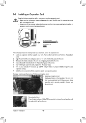
... PCI Express slot to release the card and then pull the card straight up from the chassis back panel. 2. If necessary, go to BIOS Setup to make any required BIOS changes for your computer. Example: Installing and Removing a PCI Express Graphics Card: •• Installing a Graphics Card: Gently push down on your...
... PCI Express slot to release the card and then pull the card straight up from the chassis back panel. 2. If necessary, go to BIOS Setup to make any required BIOS changes for your computer. Example: Installing and Removing a PCI Express Graphics Card: •• Installing a Graphics Card: Gently push down on your...
User Manual
Page 21
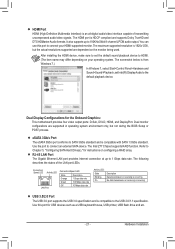
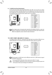
... is occurring No data transmission or receiving is occurring USB 3.0/2.0 Port The USB 3.0 port supports the USB 3.0 specification and is 1920x1200, but not during the BIOS Setup or POST process.
... is occurring No data transmission or receiving is occurring USB 3.0/2.0 Port The USB 3.0 port supports the USB 3.0 specification and is 1920x1200, but not during the BIOS Setup or POST process.
User Manual
Page 25
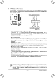
... off . 3/4) CPU_FAN/SYS_FAN1/SYS_FAN2/SYS_FAN3 (Fan Headers) All fan headers on the headers. 5) BAT (Battery) The battery provides power to keep the values (such as BIOS configurations, date, and time information) in the CMOS when the computer is replaced with an incorrect model. •• Contact the place of purchase or...
... off . 3/4) CPU_FAN/SYS_FAN1/SYS_FAN2/SYS_FAN3 (Fan Headers) All fan headers on the headers. 5) BAT (Battery) The battery provides power to keep the values (such as BIOS configurations, date, and time information) in the CMOS when the computer is replaced with an incorrect model. •• Contact the place of purchase or...
User Manual
Page 27
... pin assignments below. RESRES+ CICI+ PWR+ PWR- You may differ by issuing a beep code. When connecting your system using the power switch (refer to Chapter 2, "BIOS Setup," "Power Management," for more information). •• SPEAK (Speaker, Orange): Connects to this header, make sure the wire assignments and the pin assignments are...
... pin assignments below. RESRES+ CICI+ PWR+ PWR- You may differ by issuing a beep code. When connecting your system using the power switch (refer to Chapter 2, "BIOS Setup," "Power Management," for more information). •• SPEAK (Speaker, Orange): Connects to this header, make sure the wire assignments and the pin assignments are...
User Manual
Page 28
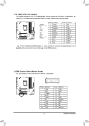
... paneBl IaOuSdSiwoitcmheord(Xu5le8At-OhaC)t has separated connectors on each wire inDsBte_PaOdRoTf a single plug. DIP 1 23 PCIe power connector (SATA)(X58A-OC) 9 1 10 2 Voltage measurement points(G1.Sniper 3) BIOS Switcher (SW4) Pin No. 1 2 3 4 5 6 7 8 9 10 Definition Power (5V) Power (5V) USB DXUSB DYUSB DX+ USB DY+ GND GND No Pin NC When the system is...
... paneBl IaOuSdSiwoitcmheord(Xu5le8At-OhaC)t has separated connectors on each wire inDsBte_PaOdRoTf a single plug. DIP 1 23 PCIe power connector (SATA)(X58A-OC) 9 1 10 2 Voltage measurement points(G1.Sniper 3) BIOS Switcher (SW4) Pin No. 1 2 3 4 5 6 7 8 9 10 Definition Power (5V) Power (5V) USB DXUSB DYUSB DX+ USB DY+ GND GND No Pin NC When the system is...
User Manual
Page 29
... 11 1 VBUS 2 SSRX1- 11 D2+ 12 D2- 3 SSRX1+ 13 GND 4 GND 14 SSTX2+ 5 SSTX1- Voltage measurement points(G1.Sniper 3) DB_PORT BIOS Switcher (SW4) BIOS Switc 1 19 TPM w/housing 1 Voltage measurement module(X58A-OC) PWM Swi 20 2 DIP Pin No. Definition Pin No. Definition Pin ... SB3V 6 NC 16 SERIRQ 7 LAD3 17 GND 8 LAD2 18 NC 9 VCC3 19 NC 10 LAD1 20 SUSCLK Voltage measurement points(G1.Sniper 3) BIOS Switcher (SW4) - 29 - Hardware Installation F_AUDIO(H) BIOS Switcher (X58A-O 1 PWM Switch (X58A-O DIP 1 23 PCIe power connector (SATA)(X58A-OC) 1 DIP 1 23 1 1 ...
... 11 1 VBUS 2 SSRX1- 11 D2+ 12 D2- 3 SSRX1+ 13 GND 4 GND 14 SSTX2+ 5 SSTX1- Voltage measurement points(G1.Sniper 3) DB_PORT BIOS Switcher (SW4) BIOS Switc 1 19 TPM w/housing 1 Voltage measurement module(X58A-OC) PWM Swi 20 2 DIP Pin No. Definition Pin No. Definition Pin ... SB3V 6 NC 16 SERIRQ 7 LAD3 17 GND 8 LAD2 18 NC 9 VCC3 19 NC 10 LAD1 20 SUSCLK Voltage measurement points(G1.Sniper 3) BIOS Switcher (SW4) - 29 - Hardware Installation F_AUDIO(H) BIOS Switcher (X58A-O 1 PWM Switch (X58A-O DIP 1 23 PCIe power connector (SATA)(X58A-OC) 1 DIP 1 23 1 1 ...
User Manual
Page 30
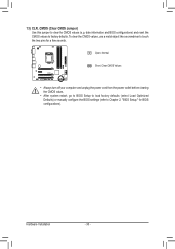
...object like a screwdriver to clear the CMOS values (e.g. 13) CLR_CMOS (Clear CMOS Jumper) Use this jumper to touch the two pins for BIOS configurations). Open: Normal Short: Clear CMOS Values •• Always turn off your computer and unplug the power cord from the power outlet ...before clearing the CMOS values. •• After system restart, go to BIOS Setup to load factory defaults (select Load Optimized Defaults) or manually configure the BIOS settings (refer to factory defaults. date information and BIOS configurations) and reset the CMOS values to Chapter...
...object like a screwdriver to clear the CMOS values (e.g. 13) CLR_CMOS (Clear CMOS Jumper) Use this jumper to touch the two pins for BIOS configurations). Open: Normal Short: Clear CMOS Values •• Always turn off your computer and unplug the power cord from the power outlet ...before clearing the CMOS values. •• After system restart, go to BIOS Setup to load factory defaults (select Load Optimized Defaults) or manually configure the BIOS settings (refer to factory defaults. date information and BIOS configurations) and reset the CMOS values to Chapter...
User Manual
Page 31
...BIOS, use either the GIGABYTE Q-Flash or @BIOS utility. •• Q-Flash allows the user to quickly and easily upgrade or back up BIOS without entering the operating system. •• @BIOS is recommended that you not alter the default settings (unless you need to) to Chapter 4, "BIOS Update Utilities." •• Because BIOS...system startup, saving system parameters and loading operating system, etc. To flash the BIOS, do not encounter problems using the current version of BIOS, it with caution. Inadequately altering the settings may result in system malfunction. •...
...BIOS, use either the GIGABYTE Q-Flash or @BIOS utility. •• Q-Flash allows the user to quickly and easily upgrade or back up BIOS without entering the operating system. •• @BIOS is recommended that you not alter the default settings (unless you need to) to Chapter 4, "BIOS Update Utilities." •• Because BIOS...system startup, saving system parameters and loading operating system, etc. To flash the BIOS, do not encounter problems using the current version of BIOS, it with caution. Inadequately altering the settings may result in system malfunction. •...
User Manual
Page 32
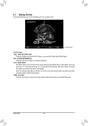
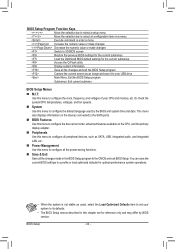
Note: The setting in BIOS Setup. : SYSTEM INFORMATION Press the key to display your system information. : BOOT MENU Boot Menu allows you ...boot from the device immediately. The system will appear when the computer boots. BIOS Setup - 32 - Function Keys Function Keys: : BIOS SETUP\Q-FLASH Press the key to enter BIOS Setup or to enter BIOS Setup first. After system restart, the device boot order will still be ...based on BIOS Setup settings. : Q-FLASH Press the key to accept. In Boot Menu, use the up arrow key or ...
Note: The setting in BIOS Setup. : SYSTEM INFORMATION Press the key to display your system information. : BOOT MENU Boot Menu allows you ...boot from the device immediately. The system will appear when the computer boots. BIOS Setup - 32 - Function Keys Function Keys: : BIOS SETUP\Q-FLASH Press the key to enter BIOS Setup or to enter BIOS Setup first. After system restart, the device boot order will still be ...based on BIOS Setup settings. : Q-FLASH Press the key to accept. In Boot Menu, use the up arrow key or ...
User Manual
Page 33
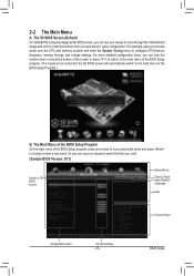
...The Main Menu A. BIOS Setup The 3D BIOS Screen (Default) On GIGABYTE's uniquely designed 3D BIOS screen, you can use your mouse to select the item you want. (Sample BIOS Version: D13) Switch to accept or enter a sub-menu. The Main Menu of the BIOS Setup Program On the main menu of the BIOS Setup Program.) B. Or...the bottom of the screen or press to switch to the main menu of the BIOS Setup program. (If a mouse is not connected, the 3D BIOS screen will automatically switch to the main menu of the BIOS Setup program, press arrow keys to move through the motherboard image and click to ...
...The Main Menu A. BIOS Setup The 3D BIOS Screen (Default) On GIGABYTE's uniquely designed 3D BIOS screen, you can use your mouse to select the item you want. (Sample BIOS Version: D13) Switch to accept or enter a sub-menu. The Main Menu of the BIOS Setup Program On the main menu of the BIOS Setup Program.) B. Or...the bottom of the screen or press to switch to the main menu of the BIOS Setup program. (If a mouse is not connected, the 3D BIOS screen will automatically switch to the main menu of the BIOS Setup program, press arrow keys to move through the motherboard image and click to ...
User Manual
Page 34
... the system/CPU temperatures, voltages, and fan speeds. „„ System Use this menu to its defaults. •• The BIOS Setup menus described in the BIOS Setup program to configure the clock, frequency, and voltages of your CPU and memory, etc. Use this menu to configure all the power... utility Display system information Save all the changes made in this chapter are for reference only and may differ by the BIOS and system time and date. BIOS Setup Program Function Keys Move the selection bar to select a setup menu Move the selection bar to select an configuration ...
... the system/CPU temperatures, voltages, and fan speeds. „„ System Use this menu to its defaults. •• The BIOS Setup menus described in the BIOS Setup program to configure the clock, frequency, and voltages of your CPU and memory, etc. Use this menu to configure all the power... utility Display system information Save all the changes made in this chapter are for reference only and may differ by the BIOS and system time and date. BIOS Setup Program Function Keys Move the selection bar to select a setup menu Move the selection bar to select an configuration ...
User Manual
Page 35
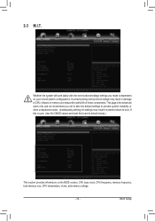
... settings may result in system's failure to CPU, chipset, or memory and reduce the useful life of these components. This page is dependent on the BIOS version, CPU base clock, CPU frequency, memory frequency, total memory size, CPU temperature, Vcore, and memory voltage. - 35 - If this occurs, clear the CMOS values...
... settings may result in system's failure to CPU, chipset, or memory and reduce the useful life of these components. This page is dependent on the BIOS version, CPU base clock, CPU frequency, memory frequency, total memory size, CPU temperature, Vcore, and memory voltage. - 35 - If this occurs, clear the CMOS values...
User Manual
Page 36
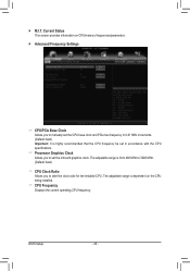
...) Important: It is from 400 MHz to 3200 MHz. (Default: Auto) && CPU Clock Ratio Allows you to alter the clock ratio for the installed CPU. BIOS Setup - 36 -
...) Important: It is from 400 MHz to 3200 MHz. (Default: Auto) && CPU Clock Ratio Allows you to alter the clock ratio for the installed CPU. BIOS Setup - 36 -
User Manual
Page 37
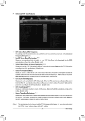
...CPU specifications. (Default: Auto) && Turbo Power Limit (Watts) Allows you to determine whether to enable all CPU cores. Auto lets the BIOS automatically configure this setting. (Default: Auto) && Turbo Ratio (1-Core Active~4-Core Active) (Note) Allows you to determine whether to enable ... to the CPU specifications. (Default: Auto) && Core Current Limit (Amps) Allows you install a CPU that support multi-processor mode. BIOS Setup Auto sets the power limit according to set the CPU Turbo ratios for operating systems that supports this function. For more information about ...
...CPU specifications. (Default: Auto) && Turbo Power Limit (Watts) Allows you to determine whether to enable all CPU cores. Auto lets the BIOS automatically configure this setting. (Default: Auto) && Turbo Ratio (1-Core Active~4-Core Active) (Note) Allows you to determine whether to enable ... to the CPU specifications. (Default: Auto) && Core Current Limit (Amps) Allows you install a CPU that support multi-processor mode. BIOS Setup Auto sets the power limit according to set the CPU Turbo ratios for operating systems that supports this function. For more information about ...


