Manual
Page 4
Table of Contents Box Contents...6 Optional Items...6 G1.Sniper 3 Motherboard Layout 7 G1.Sniper 3 Motherboard Block Diagram 8 Chapter 1 Hardware Installation 9 1-1 Installation Precautions 9 1-2 Product Specifications 10 1-3 Installing the CPU and CPU Cooler 13 1-3-1 Installing the CPU 13 1-3-2 Installing the CPU ... LEDs 24 1-10 Internal Connectors 26 Chapter 2 BIOS Setup 37 2-1 Startup Screen 38 2-2 The Main Menu 39 2-3 M.I.T...41 2-4 System...52 2-5 BIOS Features 53 2-6 Peripherals...55 2-7 Power Management 59 2-8 Save & Exit...61 - 4 -
Table of Contents Box Contents...6 Optional Items...6 G1.Sniper 3 Motherboard Layout 7 G1.Sniper 3 Motherboard Block Diagram 8 Chapter 1 Hardware Installation 9 1-1 Installation Precautions 9 1-2 Product Specifications 10 1-3 Installing the CPU and CPU Cooler 13 1-3-1 Installing the CPU 13 1-3-2 Installing the CPU ... LEDs 24 1-10 Internal Connectors 26 Chapter 2 BIOS Setup 37 2-1 Startup Screen 38 2-2 The Main Menu 39 2-3 M.I.T...41 2-4 System...52 2-5 BIOS Features 53 2-6 Peripherals...55 2-7 Power Management 59 2-8 Save & Exit...61 - 4 -
Manual
Page 6
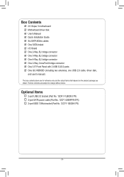
... for reference only and the actual items shall depend on the product package you obtain. G1.Sniper 3 motherboard ;; Six SATA 6Gb/s cables ;; One 3-Way SLI bridge connector ;; Optional Items 2-port USB 2.0 bracket (Part No. 12CR1-1UB030-5*R) 2-port SATA power cable (Part No. 12CF1-2SERPW-0*R) 2-port IEEE 1394a bracket (Part No. 12CF1-1IE008-0*R) - 6 - Quick...
... for reference only and the actual items shall depend on the product package you obtain. G1.Sniper 3 motherboard ;; Six SATA 6Gb/s cables ;; One 3-Way SLI bridge connector ;; Optional Items 2-port USB 2.0 bracket (Part No. 12CR1-1UB030-5*R) 2-port SATA power cable (Part No. 12CF1-2SERPW-0*R) 2-port IEEE 1394a bracket (Part No. 12CF1-1IE008-0*R) - 6 - Quick...
Manual
Page 9
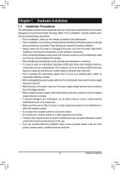
... to installation, do not remove or break motherboard S/N (Serial Number) sticker or warranty sticker provided by unplugging the power cord from the power outlet before installing or removing the motherboard or other hardware components. •• When connecting hardware components to the ...have a problem related to the local voltage standard. •• Before using the product, please verify that all cables and power connectors of electrostatic discharge (ESD). These stickers are connected tightly and securely. •• When handling the motherboard, avoid touching...
... to installation, do not remove or break motherboard S/N (Serial Number) sticker or warranty sticker provided by unplugging the power cord from the power outlet before installing or removing the motherboard or other hardware components. •• When connecting hardware components to the ...have a problem related to the local voltage standard. •• Before using the product, please verify that all cables and power connectors of electrostatic discharge (ESD). These stickers are connected tightly and securely. •• When handling the motherboard, avoid touching...
Manual
Page 11
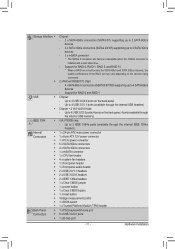
...Installation Up to 2 IEEE 1394a ports (available through the internal IEEE 1394a headers) 1 x 24-pin ATX main power connector 1 x 8-pin ATX 12V power connector 1 x PCIe power connector 6 x SATA 6Gb/s connectors 4 x SATA 3Gb/s connectors 1 x mSATA connector 1 x CPU fan ...headers 1 x front panel header 1 x front panel audio header 2 x USB 2.0/1.1 headers 2 x USB 3.0/2.0 headers 2 x IEEE 1394a headers 1 x Clear CMOS jumper 1 x power button 1 x Clear CMOS button 1 x reset button Voltage measurement points 1 x BIOS switch 1 x Trusted Platform Module (TPM) header 1 x PS/2 keyboard/mouse port 6 x...
...Installation Up to 2 IEEE 1394a ports (available through the internal IEEE 1394a headers) 1 x 24-pin ATX main power connector 1 x 8-pin ATX 12V power connector 1 x PCIe power connector 6 x SATA 6Gb/s connectors 4 x SATA 3Gb/s connectors 1 x mSATA connector 1 x CPU fan ...headers 1 x front panel header 1 x front panel audio header 2 x USB 2.0/1.1 headers 2 x USB 3.0/2.0 headers 2 x IEEE 1394a headers 1 x Clear CMOS jumper 1 x power button 1 x Clear CMOS button 1 x reset button Voltage measurement points 1 x BIOS switch 1 x Trusted Platform Module (TPM) header 1 x PS/2 keyboard/mouse port 6 x...
Manual
Page 12
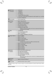
Support for eXtreme Hard Drive (X.H.D) Support for Auto Green Support for ON/OFF Charge Support for Q-Share Support for 3D Power Support for EasyTune * Available functions in EasyTune may differ by motherboard model. Back Panel Š Connectors Š Š Š Š Š I/O Controller Š...specifications and product-related information without prior notice. Support for Microsoft® Windows 7 E-ATX Form Factor; 30.5cm x 26.4cm * GIGABYTE reserves the right to make any changes to the integrated graphics port(s) on the back panel. Hardware Installation - 12 -
Support for eXtreme Hard Drive (X.H.D) Support for Auto Green Support for ON/OFF Charge Support for Q-Share Support for 3D Power Support for EasyTune * Available functions in EasyTune may differ by motherboard model. Back Panel Š Connectors Š Š Š Š Š I/O Controller Š...specifications and product-related information without prior notice. Support for Microsoft® Windows 7 E-ATX Form Factor; 30.5cm x 26.4cm * GIGABYTE reserves the right to make any changes to the integrated graphics port(s) on the back panel. Hardware Installation - 12 -
Manual
Page 13
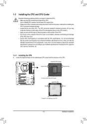
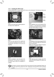
... even and thin layer of thermal grease on the surface of the CPU. •• Do not turn off the computer and unplug the power cord from the power outlet before installing the CPU to prevent hardware damage. •• Locate the pin one of the CPU Socket LGA1155 CPU Notch Notch... CPU Cooler Read the following guidelines before you begin to install the CPU: •• Make sure that the motherboard supports the CPU. (Go to GIGABYTE's website for the latest CPU support list.) •• Always turn on the computer if the CPU cooler is not recommended that the system bus...
... even and thin layer of thermal grease on the surface of the CPU. •• Do not turn off the computer and unplug the power cord from the power outlet before installing the CPU to prevent hardware damage. •• Locate the pin one of the CPU Socket LGA1155 CPU Notch Notch... CPU Cooler Read the following guidelines before you begin to install the CPU: •• Make sure that the motherboard supports the CPU. (Go to GIGABYTE's website for the latest CPU support list.) •• Always turn on the computer if the CPU cooler is not recommended that the system bus...
Manual
Page 14
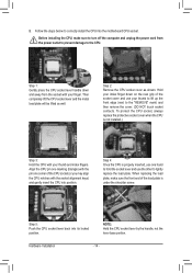
... lever and use your thumb and index fingers. Step 2: Remove the CPU socket cover as well. Hold your index finger down and away from the power outlet to prevent damage to the "REMOVE" mark) and then remove the cover. (DO NOT touch socket contacts. Step 4: Once the CPU is ... plate, make sure to correctly install the CPU into the motherboard CPU socket. Follow the steps below to turn off the computer and unplug the power cord from the socket with the socket alignment keys) and gently insert the CPU into its locked position. Step 1: Gently press the CPU socket...
... lever and use your thumb and index fingers. Step 2: Remove the CPU socket cover as well. Hold your index finger down and away from the power outlet to prevent damage to the "REMOVE" mark) and then remove the cover. (DO NOT touch socket contacts. Step 4: Once the CPU is ... plate, make sure to correctly install the CPU into the motherboard CPU socket. Follow the steps below to turn off the computer and unplug the power cord from the socket with the socket alignment keys) and gently insert the CPU into its locked position. Step 1: Gently press the CPU socket...
Manual
Page 15
Step 6: Finally, attach the power connector of the motherboard. Hardware Installation Push down each push pin. Check that the Male and Female push pins are joined closely. (Refer to your ...
Step 6: Finally, attach the power connector of the motherboard. Hardware Installation Push down each push pin. Check that the Male and Female push pins are joined closely. (Refer to your ...
Manual
Page 16
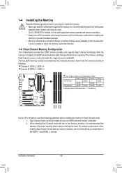
... installed in the DDR3_1 and DDR3_2 sockets. A memory module can be used . (Go to GIGABYTE's website for the latest supported memory speeds and memory modules.) • Always turn off the computer and unplug the power cord from the power outlet before installing the memory in Dual Channel mode. 1. DS/SS Four Modules DS...
... installed in the DDR3_1 and DDR3_2 sockets. A memory module can be used . (Go to GIGABYTE's website for the latest supported memory speeds and memory modules.) • Always turn off the computer and unplug the power cord from the power outlet before installing the memory in Dual Channel mode. 1. DS/SS Four Modules DS...
Manual
Page 17
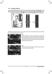
... DDR3 DIMMs on the socket. Hardware Installation 1-4-2 Installing a Memory Before installing a memory module, make sure to turn off the computer and unplug the power cord from the power outlet to prevent damage to correctly install your fingers on the top edge of the memory module. Spread the retaining clips at both ends...
... DDR3 DIMMs on the socket. Hardware Installation 1-4-2 Installing a Memory Before installing a memory module, make sure to turn off the computer and unplug the power cord from the power outlet to prevent damage to correctly install your fingers on the top edge of the memory module. Spread the retaining clips at both ends...
Manual
Page 18
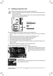
... necessary, go to BIOS Setup to make any required BIOS changes for your expansion card. • Always turn off the computer and unplug the power cord from the power outlet before you begin to install an expansion card: • Make sure the motherboard supports the expansion card. 1-5 Installing an Expansion Card Read...
... necessary, go to BIOS Setup to make any required BIOS changes for your expansion card. • Always turn off the computer and unplug the power cord from the power outlet before you begin to install an expansion card: • Make sure the motherboard supports the expansion card. 1-5 Installing an Expansion Card Read...
Manual
Page 19
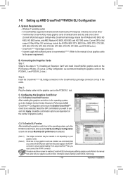
... -- Select the GPU combination you want to ensure system stability. For 4-way CrossFireX™/SLI, you connect the SATA power cable from the power supply to the ATX4P connector to use and click Apply. (Available combination options are installed, we recommend installing the graphics ...card driver in the CrossFireX/SLI gold edge connectors on the number of the cards. Procedure and driver screen for the power requirement) B. A power supply with sufficient power is enabled. (Note 1) (Note 2) The bridge connectors may differ by graphics cards. Refer to the manual of...
... -- Select the GPU combination you want to ensure system stability. For 4-way CrossFireX™/SLI, you connect the SATA power cable from the power supply to the ATX4P connector to use and click Apply. (Available combination options are installed, we recommend installing the graphics ...card driver in the CrossFireX/SLI gold edge connectors on the number of the cards. Procedure and driver screen for the power requirement) B. A power supply with sufficient power is enabled. (Note 1) (Note 2) The bridge connectors may differ by graphics cards. Refer to the manual of...
Manual
Page 20
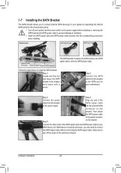
... cable from the bracket SATA signal cable to the power supply. Then attach the SATA power cable to turn off your system and the power switch on the power supply before installing or removing the SATA bracket and SATA power cable to prevent damage to the SATA port on your...connect the SATA signal cable. Before connecting the SATA signal cable, make sure to the power connector Step 5: on the bracket. SATA Bracket SATA Signal Cable SATA Power Cable External SATA Connector Power Connector External SATA Connector The SATA bracket includes one SATA bracket, two SATA signal cables...
... cable from the bracket SATA signal cable to the power supply. Then attach the SATA power cable to turn off your system and the power switch on the power supply before installing or removing the SATA bracket and SATA power cable to prevent damage to the SATA port on your...connect the SATA signal cable. Before connecting the SATA signal cable, make sure to the power connector Step 5: on the bracket. SATA Bracket SATA Signal Cable SATA Power Cable External SATA Connector Power Connector External SATA Connector The SATA bracket includes one SATA bracket, two SATA signal cables...
Manual
Page 24
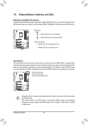
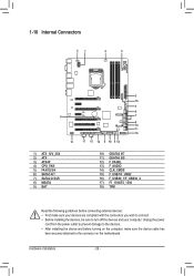
...the computer in an open-case environment when they DIP want to c1 h2DIa3P nge hardware components or conduct hardware testing. PW_SW: Power button RST_SW: Reset button CMOS_SW: Clear CMOS button 1 1 DIP DIP 1 23 1 23 PPCCIIee ppoowweerr ccoonnnneeccttoorr ((SSAATTAA))((XX5588AA--...11 BBIIOOSS SSwwiittcchheerr ((XX5588AA--OOCC)) 1 1 MM__SSAATTAA DDBB__PPOORRTT FF__PPAANNEELL((NNHH)) • Always turn on/off your computer and unplug the power cord from the backup BIOS) BIOS LED Indicators: BBIOS_LED (The backup BIOS is active) MBIOS_LED (The main BIOS is active. VVoollttaaggee...
...the computer in an open-case environment when they DIP want to c1 h2DIa3P nge hardware components or conduct hardware testing. PW_SW: Power button RST_SW: Reset button CMOS_SW: Clear CMOS button 1 1 DIP DIP 1 23 1 23 PPCCIIee ppoowweerr ccoonnnneeccttoorr ((SSAATTAA))((XX5588AA--...11 BBIIOOSS SSwwiittcchheerr ((XX5588AA--OOCC)) 1 1 MM__SSAATTAA DDBB__PPOORRTT FF__PPAANNEELL((NNHH)) • Always turn on/off your computer and unplug the power cord from the backup BIOS) BIOS LED Indicators: BBIOS_LED (The backup BIOS is active) MBIOS_LED (The main BIOS is active. VVoollttaaggee...
Manual
Page 25
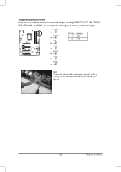
... DIP Pin 1 1 23 2 GND Voltage measurement points(G1.Sniper 3) VSA BIOS Switcher (SW4) PCIe power connector (SATA)(X58A-OC) Pin 1 Voltage measurement points(G1.Sniper 3) CPUPLL BIOS Switcher (SW4) Pin 1 Voltage measurement points(G1.Sniper 3) DDRVTT BIOS Switcher (SW4) Pin 1 Voltage measurement points(G1.Sniper 3) VDIMM BIOS Switcher (SW4) Pin 1 Voltage measurement points(G1.Sniper 3) PCHIO BIOS Switcher (SW4) Pin 1 M_SATA...
... DIP Pin 1 1 23 2 GND Voltage measurement points(G1.Sniper 3) VSA BIOS Switcher (SW4) PCIe power connector (SATA)(X58A-OC) Pin 1 Voltage measurement points(G1.Sniper 3) CPUPLL BIOS Switcher (SW4) Pin 1 Voltage measurement points(G1.Sniper 3) DDRVTT BIOS Switcher (SW4) Pin 1 Voltage measurement points(G1.Sniper 3) VDIMM BIOS Switcher (SW4) Pin 1 Voltage measurement points(G1.Sniper 3) PCHIO BIOS Switcher (SW4) Pin 1 M_SATA...
Manual
Page 26
Unplug the power cord from the power outlet to prevent damage to the devices. •• After installing the device and before connecting external devices: •• First make sure the device ...
Unplug the power cord from the power outlet to prevent damage to the devices. •• After installing the device and before connecting external devices: •• First make sure the device ...
Manual
Page 27
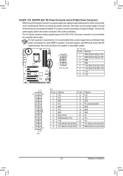
...: Pin No. The power connector possesses a foolproof design. The 12V power connector mainly supplies power to the power connector in the correct orientation. 1/2) ATX_12V_2X4/ATX (2x4 12V Power Connector and 2x12 Main Power Connector) With the use of the power connector, the power supply can withstand high power consumption be used that can...No. 1 2 3 4 5 6 7 8 9 10 11 12 Definition Pin No. 3.3V 13 3.3V 14 GND 15 +5V 16 GND 17 +5V 18 GND 19 Power Good 20 5VSB (stand by +5V) 21 +12V 22 +12V (Only for 2x12-pin ATX) 23 3.3V (Only for 2x12-pin ATX) 24 Definition 3.3V...
...: Pin No. The power connector possesses a foolproof design. The 12V power connector mainly supplies power to the power connector in the correct orientation. 1/2) ATX_12V_2X4/ATX (2x4 12V Power Connector and 2x12 Main Power Connector) With the use of the power connector, the power supply can withstand high power consumption be used that can...No. 1 2 3 4 5 6 7 8 9 10 11 12 Definition Pin No. 3.3V 13 3.3V 14 GND 15 +5V 16 GND 17 +5V 18 GND 19 Power Good 20 5VSB (stand by +5V) 21 +12V 22 +12V (Only for 2x12-pin ATX) 23 3.3V (Only for 2x12-pin ATX) 24 Definition 3.3V...
Manual
Page 28
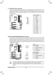
... BIOS Switcher (X58A-OC) 1 M_SATA F_PANEL(NH) PWM Switch (X58A-OC) 3) ATX4P (PCIe Power Connector) The power connector provides auxiliary power to prevent your CPU and system from the power supply to the ATX4P connector to connect it is the ground wire). The speed control function requires the... 1 CPU_FAN CPU_FAN: Pin No. Definition 1 NC BIOS Switcher (SW4) 2 NC 1 3 NC 4 GND 5 GND 15 6 GND 7 VCC Voltage measurement points(G1.Sniper 3) 8 VCC 9 VCC 10 GND 11 GND 12 GND 13 +12V 14 +12V 15 +12V F_AUDIO(H) F_USB30 TPM w/housing 4/5) CPU_FAN/FAN1/FAN2/FAN3/FAN4 (Fan...
... BIOS Switcher (X58A-OC) 1 M_SATA F_PANEL(NH) PWM Switch (X58A-OC) 3) ATX4P (PCIe Power Connector) The power connector provides auxiliary power to prevent your CPU and system from the power supply to the ATX4P connector to connect it is the ground wire). The speed control function requires the... 1 CPU_FAN CPU_FAN: Pin No. Definition 1 NC BIOS Switcher (SW4) 2 NC 1 3 NC 4 GND 5 GND 15 6 GND 7 VCC Voltage measurement points(G1.Sniper 3) 8 VCC 9 VCC 10 GND 11 GND 12 GND 13 +12V 14 +12V 15 +12V F_AUDIO(H) F_USB30 TPM w/housing 4/5) CPU_FAN/FAN1/FAN2/FAN3/FAN4 (Fan...
Manual
Page 30
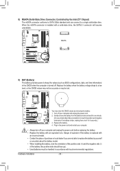
...(X58A-OC) 1 M_SATA F_PANEL(NH) BIOS Switcher (SW4) Voltage measurement points(G1.Sniper 3) DIP 1 23 PCIe power connector (SATA)(X58A-OC) DIP 1 23 1 DIP 1 23 1 DIP 1 23 1 9) BAT (Battery) The battery provides power to keep the values (such as BIOS configurations, date, and time information) in...housing •• Always turn off your computer and unplug the power cord. 2. Voltage measurement module(X58A-OC) DB_PORT F_AUDIO(H) You may be handled in the power cord and restart your computer and unplug the power cord before replacing the battery. •• Replace the battery...
...(X58A-OC) 1 M_SATA F_PANEL(NH) BIOS Switcher (SW4) Voltage measurement points(G1.Sniper 3) DIP 1 23 PCIe power connector (SATA)(X58A-OC) DIP 1 23 1 DIP 1 23 1 DIP 1 23 1 9) BAT (Battery) The battery provides power to keep the values (such as BIOS configurations, date, and time information) in...housing •• Always turn off your computer and unplug the power cord. 2. Voltage measurement module(X58A-OC) DB_PORT F_AUDIO(H) You may be handled in the power cord and restart your computer and unplug the power cord before replacing the battery. •• Replace the battery...
Manual
Page 32
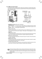
...8226;• CI (Chassis Intrusion Header, Gray): Connects to the chassis intrusion switch/sensor on the chassis front panel. Message/Power/ Power Sleep LED Switch Speaker MSG+ MSG- This function requires a chassis with a chassis intrusion switch/sensor. When connecting your system using the...; RES (Reset Switch, Green): Connects to the reset switch on the chassis front panel. 12) F_PANEL (Front Panel Header) Connect the power switch, reset switch, speaker, chassis intrusion switch/sensor and system status indicator on the chassis to this header, make sure the wire assignments...
...8226;• CI (Chassis Intrusion Header, Gray): Connects to the chassis intrusion switch/sensor on the chassis front panel. Message/Power/ Power Sleep LED Switch Speaker MSG+ MSG- This function requires a chassis with a chassis intrusion switch/sensor. When connecting your system using the...; RES (Reset Switch, Green): Connects to the reset switch on the chassis front panel. 12) F_PANEL (Front Panel Header) Connect the power switch, reset switch, speaker, chassis intrusion switch/sensor and system status indicator on the chassis to this header, make sure the wire assignments...


