
Manual
Page 1
G1.Assassin LGA1366 socket motherboard for Intel® Core™ i7 processor family User's Manual Rev. 1002 12ME-G1ASSAS-1002R
G1.Assassin LGA1366 socket motherboard for Intel® Core™ i7 processor family User's Manual Rev. 1002 12ME-G1ASSAS-1002R

Manual
Page 3
... Guide included with the product. For detailed product information, carefully read the User's Manual. Example: The trademarks mentioned in this manual may be made by any form or by GIGABYTE without GIGABYTE's prior written permission. Check your motherboard looks like this product, GIGABYTE provides the following types of documentations: For quick set-up of...
... Guide included with the product. For detailed product information, carefully read the User's Manual. Example: The trademarks mentioned in this manual may be made by any form or by GIGABYTE without GIGABYTE's prior written permission. Check your motherboard looks like this product, GIGABYTE provides the following types of documentations: For quick set-up of...

Manual
Page 6
Optional Items 2-port USB 2.0 bracket (Part No. 12CR1-1UB030-5*R) 2-port SATA power cable (Part No. 12CF1-2SERPW-0*R) - 6 - Box Contents G1.Assassin motherboard Motherboard driver disk User's Manual Quick Installation Guide Four SATA cables I/O Shield 5.25" Front Access Control Panel with 2 USB 3.0/2.0 ports, 1 Power eSATA port, and 1 Quick Boost button One 2-Way SLI ...
Optional Items 2-port USB 2.0 bracket (Part No. 12CR1-1UB030-5*R) 2-port SATA power cable (Part No. 12CF1-2SERPW-0*R) - 6 - Box Contents G1.Assassin motherboard Motherboard driver disk User's Manual Quick Installation Guide Four SATA cables I/O Shield 5.25" Front Access Control Panel with 2 USB 3.0/2.0 ports, 1 Power eSATA port, and 1 Quick Boost button One 2-Way SLI ...

Manual
Page 9
...carefully read the user's manual and follow these procedures: • Prior to installation, do not allow screws to come in contact with the motherboard circuit or its components. • Make sure there are no leftover screws or metal components placed on the motherboard or within an electrostatic ...please verify that all cables and power connectors of your hardware components are connected. • To prevent damage to the motherboard, do not remove or break motherboard S/N (Serial Number) sticker or warranty sticker provided by your hands dry and first touch a metal object to eliminate ...
...carefully read the user's manual and follow these procedures: • Prior to installation, do not allow screws to come in contact with the motherboard circuit or its components. • Make sure there are no leftover screws or metal components placed on the motherboard or within an electrostatic ...please verify that all cables and power connectors of your hardware components are connected. • To prevent damage to the motherboard, do not remove or break motherboard S/N (Serial Number) sticker or warranty sticker provided by your hands dry and first touch a metal object to eliminate ...

Manual
Page 15
... CPU, aligning the four push pins through the pin holes on the motherboard. Step 4: You should hear a "click" when pushing down on the motherboard. Check that the Male and Female push pins are joined closely. (Refer to your CPU cooler installation manual for instructions on installing the cooler.) Step 5: After the installation, check...
... CPU, aligning the four push pins through the pin holes on the motherboard. Step 4: You should hear a "click" when pushing down on the motherboard. Check that the Male and Female push pins are joined closely. (Refer to your CPU cooler installation manual for instructions on installing the cooler.) Step 5: After the installation, check...
Manual
Page 18
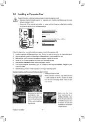
... back on the lever on your expansion card(s). 7. Secure the card's metal bracket to install an expansion card: • Make sure the motherboard supports the expansion card. After installing all expansion cards, replace the chassis cover(s). 6. Hardware Installation - 18 - • Removing the Card ...from the power outlet before you begin to the chassis back panel with a screw. 5. Carefully read the manual that supports your expansion card. • Always turn off the computer and unplug the power cord from the PCIEX16_2/ PCIEX8_1/PCIEX8_2 Slot: Press ...
... back on the lever on your expansion card(s). 7. Secure the card's metal bracket to install an expansion card: • Make sure the motherboard supports the expansion card. After installing all expansion cards, replace the chassis cover(s). 6. Hardware Installation - 18 - • Removing the Card ...from the power outlet before you begin to the chassis back panel with a screw. 5. Carefully read the manual that supports your expansion card. • Always turn off the computer and unplug the power cord from the PCIEX16_2/ PCIEX8_1/PCIEX8_2 Slot: Press ...
Manual
Page 19
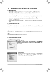
... cards of the graphics cards. Connecting the Graphics Cards Step 1: Observe the steps in the operating system, go to the manual of ATI CrossFireX™/NVIDIA SLI Configuration A. A CrossFireX/SLI-supported motherboard with sufficient power is selected. A power supply with two/three/four PCI Express x16 slots and correct driver - Browse to...
... cards of the graphics cards. Connecting the Graphics Cards Step 1: Observe the steps in the operating system, go to the manual of ATI CrossFireX™/NVIDIA SLI Configuration A. A CrossFireX/SLI-supported motherboard with sufficient power is selected. A power supply with two/three/four PCI Express x16 slots and correct driver - Browse to...

Manual
Page 32
...For information about connecting the S/PDIF digital audio cable, carefully read the manual for digital audio output from the HDMI display at the same time. Incorrect connection between the module connector and the motherboard header will make the device unable to this header. For information about... connecting the front panel audio module that has separated connectors on each wire instead of the motherboard header. Make sure the wire assignments of the module connector match the pin assignments of a single plug. For example, ...
...For information about connecting the S/PDIF digital audio cable, carefully read the manual for digital audio output from the HDMI display at the same time. Incorrect connection between the module connector and the motherboard header will make the device unable to this header. For information about... connecting the front panel audio module that has separated connectors on each wire instead of the motherboard header. Make sure the wire assignments of the module connector match the pin assignments of a single plug. For example, ...
Manual
Page 34
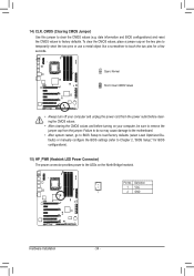
... on your computer, be sure to factory defaults. Failure to do so may cause damage to the motherboard. • After system restart, go to BIOS Setup to load factory defaults (select Load Optimized Defaults) or manually configure the BIOS settings (refer to clear the CMOS values (e.g. Definition 1 VCC 1 2 GND Hardware Installation - 34...
... on your computer, be sure to factory defaults. Failure to do so may cause damage to the motherboard. • After system restart, go to BIOS Setup to load factory defaults (select Load Optimized Defaults) or manually configure the BIOS settings (refer to clear the CMOS values (e.g. Definition 1 VCC 1 2 GND Hardware Installation - 34...

Manual
Page 60
...fails. Options are : Disabled (default), 60oC/140oF, 70oC/158oF, 80oC/176oF, 90oC/194oF. Slope PWM Allows you to Manual. Current CPU Temperature Displays current CPU temperature. Manual Allows you to the CPU temperature. Check the fan condition or fan connection when this occurs. (Default: Disabled) CPU .... Options are : 0.75 PWM value /oC ~ 2.50 PWM value /oC. You can adjust the fan speed with EasyTune based on the motherboard. Disabled Allows the CPU fan to run at different speeds according to control the CPU fan speed. BIOS Setup - 60 - Current System Temperature/...
...fails. Options are : Disabled (default), 60oC/140oF, 70oC/158oF, 80oC/176oF, 90oC/194oF. Slope PWM Allows you to Manual. Current CPU Temperature Displays current CPU temperature. Manual Allows you to the CPU temperature. Check the fan condition or fan connection when this occurs. (Default: Disabled) CPU .... Options are : 0.75 PWM value /oC ~ 2.50 PWM value /oC. You can adjust the fan speed with EasyTune based on the motherboard. Disabled Allows the CPU fan to run at different speeds according to control the CPU fan speed. BIOS Setup - 60 - Current System Temperature/...
Manual
Page 65
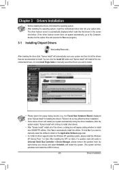
...drivers, first install the operating system. • After installing the operating system, insert the motherboard driver disk into your system and then list all the recommended drivers. the Found New ... "Xpress Install" is automatically displayed which looks like that are recommended to install new GIGABYTE utilities. Or click No if you wish to automatically install the utilities. Click Yes... appear asking whether to install. Or click Install Single Items to manually select the drivers you want to manually select the utilities to do so may affect the driver installation....
...drivers, first install the operating system. • After installing the operating system, insert the motherboard driver disk into your system and then list all the recommended drivers. the Found New ... "Xpress Install" is automatically displayed which looks like that are recommended to install new GIGABYTE utilities. Or click No if you wish to automatically install the utilities. Click Yes... appear asking whether to install. Or click Install Single Items to manually select the drivers you want to manually select the utilities to do so may affect the driver installation....
Manual
Page 66
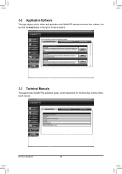
Drivers Installation - 66 - You can click the Install button on the right of an item to install it. 3-3 Technical Manuals This page provides GIGABYTE's application guides, content descriptions for this driver disk, and the motherboard manuals. 3-2 Application Software This page displays all the utilities and applications that GIGABYTE develops and some free software.
Drivers Installation - 66 - You can click the Install button on the right of an item to install it. 3-3 Technical Manuals This page provides GIGABYTE's application guides, content descriptions for this driver disk, and the motherboard manuals. 3-2 Application Software This page displays all the utilities and applications that GIGABYTE develops and some free software.

Manual
Page 72
... in the Windows environment. @BIOS will take over on the main BIOS. Assassin F1c . . . . : BIOS Setup : XpressRecovery2 : Boot Menu :... hard drive attached to access Q-Flash. Unique Features - 72 - G1. GIGABYTE Q-Flash and @BIOS are easy-to-use and allow you from the...4-2 BIOS Update Utilities GIGABYTE motherboards provide two unique BIOS update tools, Q-Flash™ and @BIOS™. Additionally, this motherboard features the DualBIOS™...users cannot update the backup BIOS manually. What is saved to a hard drive in system malfunction. Motherboards that matches your USB flash drive,...
... in the Windows environment. @BIOS will take over on the main BIOS. Assassin F1c . . . . : BIOS Setup : XpressRecovery2 : Boot Menu :... hard drive attached to access Q-Flash. Unique Features - 72 - G1. GIGABYTE Q-Flash and @BIOS are easy-to-use and allow you from the...4-2 BIOS Update Utilities GIGABYTE motherboards provide two unique BIOS update tools, Q-Flash™ and @BIOS™. Additionally, this motherboard features the DualBIOS™...users cannot update the backup BIOS manually. What is saved to a hard drive in system malfunction. Motherboards that matches your USB flash drive,...

Manual
Page 75
... BIOS file to complete. 3. B. After Updating the BIOS Restart your motherboard model. Using @BIOS 1. Unique Features Follow the on the @BIOS server site, please manually download the BIOS update file from GIGABYTE Server, select the @BIOS server site closest to start. 3. 4-2-2 ...Updating the BIOS with an incorrect BIOS file could cause your motherboard model. Save the Current BIOS File: Click...
... BIOS file to complete. 3. B. After Updating the BIOS Restart your motherboard model. Using @BIOS 1. Unique Features Follow the on the @BIOS server site, please manually download the BIOS update file from GIGABYTE Server, select the @BIOS server site closest to start. 3. 4-2-2 ...Updating the BIOS with an incorrect BIOS file could cause your motherboard model. Save the Current BIOS File: Click...
Manual
Page 85
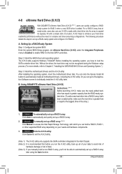
... and quickly set up a RAID 0 array: Click Auto to the biggest drive in the array. ) 1. A. To manually set up all motherboard drivers, including the X.H.D utility. All with which you have to enhance your needs and hardware components. 3. Without the driver... using the Auto function. - 85 - Step 2: Install the RAID driver and operating system The X.H.D utility supports Windows 7/Vista/XP. Using GIGABYTE eXtreme Hard Drive (X.H.D) Instructions: (Note 2) Before launching X.H.D, make sure the new drive is added. Before installing the operating system, you can...
... and quickly set up a RAID 0 array: Click Auto to the biggest drive in the array. ) 1. A. To manually set up all motherboard drivers, including the X.H.D utility. All with which you have to enhance your needs and hardware components. 3. Without the driver... using the Auto function. - 85 - Step 2: Install the RAID driver and operating system The X.H.D utility supports Windows 7/Vista/XP. Using GIGABYTE eXtreme Hard Drive (X.H.D) Instructions: (Note 2) Before launching X.H.D, make sure the new drive is added. Before installing the operating system, you can...

Manual
Page 109
While in the operating system, launch the Marvell Storage Utility from the motherboard driver disk. Step 1: Under Virtual Disk 0, click the Operation tab and select Rebuild. Appendix When completed, the status will display the new hard drive. Under ... Utility\Marvell Tray, right-click on the icon in the RAID setup utility first. Step 2: The screen will display as Done. • Manually Rebuilding RAID 1 in the Operating System You can manually rebuild a RAID 1 array without setting the new hard drive as a Spare drive in the notification area, and select Open MSU.
While in the operating system, launch the Marvell Storage Utility from the motherboard driver disk. Step 1: Under Virtual Disk 0, click the Operation tab and select Rebuild. Appendix When completed, the status will display the new hard drive. Under ... Utility\Marvell Tray, right-click on the icon in the RAID setup utility first. Step 2: The screen will display as Done. • Manually Rebuilding RAID 1 in the Operating System You can manually rebuild a RAID 1 array without setting the new hard drive as a Spare drive in the notification area, and select Open MSU.


