Manual
Page 4
Table of Contents Box Contents...6 Optional Items...6 G1.Assassin Motherboard Layout 7 G1.Assassin Motherboard Block Diagram 8 Chapter 1 Hardware Installation 9 1-1 Installation Precautions 9 1-2 Product Specifications 10 1-3 Installing the CPU and CPU Cooler 13 1-3-1 ...Screen 38 2-2 The Main Menu 39 2-3 MB Intelligent Tweaker(M.I.T 41 2-4 Standard CMOS Features 51 2-5 Advanced BIOS Features 53 2-6 Integrated Peripherals 55 2-7 Power Management Setup 57 2-8 PC Health Status 59 2-9 Load Fail-Safe Defaults 61 2-10 Load Optimized Defaults 61 2-11 Set Supervisor/User Password 62 2-...
Table of Contents Box Contents...6 Optional Items...6 G1.Assassin Motherboard Layout 7 G1.Assassin Motherboard Block Diagram 8 Chapter 1 Hardware Installation 9 1-1 Installation Precautions 9 1-2 Product Specifications 10 1-3 Installing the CPU and CPU Cooler 13 1-3-1 ...Screen 38 2-2 The Main Menu 39 2-3 MB Intelligent Tweaker(M.I.T 41 2-4 Standard CMOS Features 51 2-5 Advanced BIOS Features 53 2-6 Integrated Peripherals 55 2-7 Power Management Setup 57 2-8 PC Health Status 59 2-9 Load Fail-Safe Defaults 61 2-10 Load Optimized Defaults 61 2-11 Set Supervisor/User Password 62 2-...

Manual
Page 6
.... Optional Items 2-port USB 2.0 bracket (Part No. 12CR1-1UB030-5*R) 2-port SATA power cable (Part No. 12CF1-2SERPW-0*R) - 6 - Box Contents G1.Assassin motherboard Motherboard driver disk User's Manual Quick Installation Guide Four SATA cables I/O Shield 5.25" Front Access Control Panel with 2 USB 3.0/2.0 ports, 1 Power eSATA port, and 1 Quick Boost button One 2-Way SLI bridge connector...
.... Optional Items 2-port USB 2.0 bracket (Part No. 12CR1-1UB030-5*R) 2-port SATA power cable (Part No. 12CF1-2SERPW-0*R) - 6 - Box Contents G1.Assassin motherboard Motherboard driver disk User's Manual Quick Installation Guide Four SATA cables I/O Shield 5.25" Front Access Control Panel with 2 USB 3.0/2.0 ports, 1 Power eSATA port, and 1 Quick Boost button One 2-Way SLI bridge connector...

Manual
Page 9
...connectors. • It is best to the local voltage standard. • Before using the product, please verify that all cables and power connectors of the product, please consult a certified computer technician. - 9 - Chapter 1 Hardware Installation 1-1 Installation Precautions The motherboard contains ... or metal components placed on the motherboard or within an electrostatic shielding container. • Before unplugging the power supply cable from the power outlet before installing or removing the motherboard or other hardware components. • When connecting hardware components to...
...connectors. • It is best to the local voltage standard. • Before using the product, please verify that all cables and power connectors of the product, please consult a certified computer technician. - 9 - Chapter 1 Hardware Installation 1-1 Installation Precautions The motherboard contains ... or metal components placed on the motherboard or within an electrostatic shielding container. • Before unplugging the power supply cable from the power outlet before installing or removing the motherboard or other hardware components. • When connecting hardware components to...

Manual
Page 11
... signals of the USB 3.0/2.0 ports are from the South Bridge. ŠŠ 1 x 24-pin ATX main power connector ŠŠ 2 x 8-pin ATX 12V power connectors ŠŠ 2 x 4-pin PCIe 12V power connectors ŠŠ 2 x SATA 6Gb/s connectors ŠŠ 6 x SATA 3Gb/s connectors ŠŠ...headers ŠŠ 2 x USB 3.0/2.0 headers ŠŠ 1 x clearing CMOS jumper ŠŠ 1 x Quick Boost button header ŠŠ 1 x heatsink LED power connector ŠŠ 1 x PS/2 keyboard port ŠŠ 1 x PS/2 mouse port ŠŠ 1 x optical S/PDIF Out connector ŠŠ 1 x...
... signals of the USB 3.0/2.0 ports are from the South Bridge. ŠŠ 1 x 24-pin ATX main power connector ŠŠ 2 x 8-pin ATX 12V power connectors ŠŠ 2 x 4-pin PCIe 12V power connectors ŠŠ 2 x SATA 6Gb/s connectors ŠŠ 6 x SATA 3Gb/s connectors ŠŠ...headers ŠŠ 2 x USB 3.0/2.0 headers ŠŠ 1 x clearing CMOS jumper ŠŠ 1 x Quick Boost button header ŠŠ 1 x heatsink LED power connector ŠŠ 1 x PS/2 keyboard port ŠŠ 1 x PS/2 mouse port ŠŠ 1 x optical S/PDIF Out connector ŠŠ 1 x...

Manual
Page 13
... latest CPU support list.) • Always turn on the computer if the CPU cooler is not recommended that the motherboard supports the CPU. (Go to GIGABYTE's website for the peripherals. Locate the alignment keys on the motherboard CPU socket and the notches on the CPU Notch Notch - 13 - It is not... pin one of the CPU. LGA1366 CPU Socket Pin One Corner of the CPU. • Do not turn off the computer and unplug the power cord from the power outlet before you begin to install the CPU: • Make sure that the system bus frequency be inserted if oriented incorrectly. (Or you...
... latest CPU support list.) • Always turn on the computer if the CPU cooler is not recommended that the motherboard supports the CPU. (Go to GIGABYTE's website for the peripherals. Locate the alignment keys on the motherboard CPU socket and the notches on the CPU Notch Notch - 13 - It is not... pin one of the CPU. LGA1366 CPU Socket Pin One Corner of the CPU. • Do not turn off the computer and unplug the power cord from the power outlet before you begin to install the CPU: • Make sure that the system bus frequency be inserted if oriented incorrectly. (Or you...

Manual
Page 14
... your finger. Then completely lift the CPU socket lever. Before installing the CPU, make sure to turn off the computer and unplug the power cord from the power outlet to prevent damage to correctly install the CPU into its locked position. Align the CPU pin one marking (triangle) with the pin one...
... your finger. Then completely lift the CPU socket lever. Before installing the CPU, make sure to turn off the computer and unplug the power cord from the power outlet to prevent damage to correctly install the CPU into its locked position. Align the CPU pin one marking (triangle) with the pin one...

Manual
Page 15
... cooler and CPU may damage the CPU. - 15 - Step 4: You should hear a "click" when pushing down on the push pins diagonally. Step 6: Finally, attach the power connector of the CPU cooler to the CPU fan header (CPU_FAN) on the motherboard. Inadequately removing the CPU cooler may adhere to the CPU. Direction...
... cooler and CPU may damage the CPU. - 15 - Step 4: You should hear a "click" when pushing down on the push pins diagonally. Step 6: Finally, attach the power connector of the CPU cooler to the CPU fan header (CPU_FAN) on the motherboard. Inadequately removing the CPU cooler may adhere to the CPU. Direction...

Manual
Page 16
... modules, it in Dual or 3 Channel mode. A memory module can be used . (Go to GIGABYTE's website for the latest supported memory speeds and momery moudles.) • Always turn off the computer and unplug the power cord from the power outlet before installing the memory to insert the memory, switch the direction. 1-4-1 Dual/3 Channel...
... modules, it in Dual or 3 Channel mode. A memory module can be used . (Go to GIGABYTE's website for the latest supported memory speeds and momery moudles.) • Always turn off the computer and unplug the power cord from the power outlet before installing the memory to insert the memory, switch the direction. 1-4-1 Dual/3 Channel...

Manual
Page 17
... the memory, push down on the socket. 1-4-2 Installing a Memory Before installing a memory module, make sure to turn off the computer and unplug the power cord from the power outlet to prevent damage to install DDR3 DIMMs on this motherboard. As indicated in the picture on the left, place your memory modules in...
... the memory, push down on the socket. 1-4-2 Installing a Memory Before installing a memory module, make sure to turn off the computer and unplug the power cord from the power outlet to prevent damage to install DDR3 DIMMs on this motherboard. As indicated in the picture on the left, place your memory modules in...
Manual
Page 18
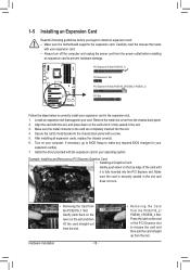
... in your expansion card(s). 7. Locate an expansion slot that came with your expansion card. • Always turn off the computer and unplug the power cord from the slot. Turn on the slot and then lift the card straight out from the chassis back panel. 2. Install the driver provided ... the metal contacts on the top edge of the PCI Express slot to release the card and then pull the card straight up from the power outlet before you begin to the chassis back panel with a screw. 5. After installing all expansion cards, replace the chassis cover(s). 6. 1-5 Installing an Expansion...
... in your expansion card(s). 7. Locate an expansion slot that came with your expansion card. • Always turn off the computer and unplug the power cord from the slot. Turn on the slot and then lift the card straight out from the chassis back panel. 2. Install the driver provided ... the metal contacts on the top edge of the PCI Express slot to release the card and then pull the card straight up from the power outlet before you begin to the chassis back panel with a screw. 5. After installing all expansion cards, replace the chassis cover(s). 6. 1-5 Installing an Expansion...
Manual
Page 19
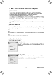
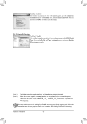
... include the ATI Radeon HD 3800, HD 4800, and HD 5800 series and AMD Radeon HD 6950 and HD 6970 series. A power supply with two/three/four PCI Express x16 slots and correct driver - Hardware Installation Connecting the Graphics Cards Step 1: Observe the steps... select the Enable CrossFireX™ check box, and select the 3 GPUs combination. CrossFireX/SLI-supported graphics cards of your graphics cards for the power require ment) B. The 3-Way SLI and 3-Way/4-Way CrossFireX technologies currently support Windows 7 and Vista operating systems - 1-6 Setup of the graphics...
... include the ATI Radeon HD 3800, HD 4800, and HD 5800 series and AMD Radeon HD 6950 and HD 6970 series. A power supply with two/three/four PCI Express x16 slots and correct driver - Hardware Installation Connecting the Graphics Cards Step 1: Observe the steps... select the Enable CrossFireX™ check box, and select the 3 GPUs combination. CrossFireX/SLI-supported graphics cards of your graphics cards for the power require ment) B. The 3-Way SLI and 3-Way/4-Way CrossFireX technologies currently support Windows 7 and Vista operating systems - 1-6 Setup of the graphics...
Manual
Page 20
... to apply. Hardware Installation - 20 - Procedure and driver screen for more information about enabling CrossFireX/SLI technology. Refer to the manual that you connect the power cables from the power supply to the PCIE_12V_1 and PCIE_12V_2 connectors, or system instability may differ by graphics cards.
... to apply. Hardware Installation - 20 - Procedure and driver screen for more information about enabling CrossFireX/SLI technology. Refer to the manual that you connect the power cables from the power supply to the PCIE_12V_1 and PCIE_12V_2 connectors, or system instability may differ by graphics cards.
Manual
Page 21
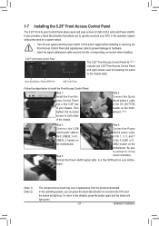
...Note 2) The components received may vary in the Step 5: correct orientation. To return to a free SATA port on of the chassis. Connect the Power eSATA signal cable to the defaults, press the button again and the button will light red. It also provides a Quick Boost button that allows ... a system reboot. • Turn off your system and the power switch on the power supply before installing or removing the Front Access Control Panel and signal/power cable to prevent damage to hardware. • Insert the signal cable/power cable securely into a free 5.25" bay of your mother- ...
...Note 2) The components received may vary in the Step 5: correct orientation. To return to a free SATA port on of the chassis. Connect the Power eSATA signal cable to the defaults, press the button again and the button will light red. It also provides a Quick Boost button that allows ... a system reboot. • Turn off your system and the power switch on the power supply before installing or removing the Front Access Control Panel and signal/power cable to prevent damage to hardware. • Insert the signal cable/power cable securely into a free 5.25" bay of your mother- ...

Manual
Page 27
... with the connectors you wish to connect. • Before installing the devices, be sure to the connector on the motherboard. - 27 - Unplug the power cord from the power outlet to prevent damage to the devices. • After installing the device and before connecting external devices: • First make sure the device cable...
... with the connectors you wish to connect. • Before installing the devices, be sure to the connector on the motherboard. - 27 - Unplug the power cord from the power outlet to prevent damage to the devices. • After installing the device and before connecting external devices: • First make sure the device cable...

Manual
Page 28
... 2 3 4 5 6 7 8 9 10 11 12 Definition Pin No. 3.3V 13 3.3V 14 GND 15 +5V 16 GND 17 +5V 18 GND 19 Power Good 20 5VSB (stand by the CPU manufacturer when using an Intel Extreme Edition CPU (130W). • To meet expansion requirements, it is turned off...unbootable system. 8 4 5 1 ATX_12V_2X/ATX_12V_2X_1 ATX_12V_2X/ATX_12V_2X_1: Pin No. 1/2) ATX_12V_2X/ATX_12V_2X_1/ATX (2x4 12V Power Connectors and 2x12 Main Power Connector) With the use of a power supply providing a 2x4 12V power connector is recommended by +5V) 21 +12V 22 +12V (Only for 2x12-pin ATX) 23 3.3V ...
... 2 3 4 5 6 7 8 9 10 11 12 Definition Pin No. 3.3V 13 3.3V 14 GND 15 +5V 16 GND 17 +5V 18 GND 19 Power Good 20 5VSB (stand by the CPU manufacturer when using an Intel Extreme Edition CPU (130W). • To meet expansion requirements, it is turned off...unbootable system. 8 4 5 1 ATX_12V_2X/ATX_12V_2X_1 ATX_12V_2X/ATX_12V_2X_1: Pin No. 1/2) ATX_12V_2X/ATX_12V_2X_1/ATX (2x4 12V Power Connectors and 2x12 Main Power Connector) With the use of a power supply providing a 2x4 12V power connector is recommended by +5V) 21 +12V 22 +12V (Only for 2x12-pin ATX) 23 3.3V ...

Manual
Page 29
... PCI Express x16 slots. Do not place a jumper cap on this motherboard are not configuration jumper blocks. 3) PCIE_12V_1/PCIE_12V_2 (Power Connectors) The power connectors provide auxiliary power to connect it is the ground wire). When connecting a fan cable, be installed inside the chassis. 1 CPU_FAN 1 SYS_FAN ...fan headers on the headers. - 29 - For optimum heat dissipation, it in damage to prevent your CPU and system from the power supply to the PCIE_12V_1 and PCIE_12V_2 connectors, or system instability may hang. • These fan headers are 4-pin and support fan speed...
... PCI Express x16 slots. Do not place a jumper cap on this motherboard are not configuration jumper blocks. 3) PCIE_12V_1/PCIE_12V_2 (Power Connectors) The power connectors provide auxiliary power to connect it is the ground wire). When connecting a fan cable, be installed inside the chassis. 1 CPU_FAN 1 SYS_FAN ...fan headers on the headers. - 29 - For optimum heat dissipation, it in damage to prevent your CPU and system from the power supply to the PCIE_12V_1 and PCIE_12V_2 connectors, or system instability may hang. • These fan headers are 4-pin and support fan speed...

Manual
Page 31
...problem is in S1 sleep state. The LED is on when the hard drive is operating. A front panel module mainly consists of power switch, reset switch, power LED, hard drive activity LED, speaker and etc. Note the positive and negative pins before connecting the cables. The LED S0 ...header, make sure the wire assignments and the pin assignments are matched correctly. - 31 - You may differ by issuing a beep code. Message/Power/ Power Sleep LED Switch Speaker MSG+ MSG- The system reports system startup status by chassis. The front panel design may configure the way to turn ...
...problem is in S1 sleep state. The LED is on when the hard drive is operating. A front panel module mainly consists of power switch, reset switch, power LED, hard drive activity LED, speaker and etc. Note the positive and negative pins before connecting the cables. The LED S0 ...header, make sure the wire assignments and the pin assignments are matched correctly. - 31 - You may differ by issuing a beep code. Message/Power/ Power Sleep LED Switch Speaker MSG+ MSG- The system reports system startup status by chassis. The front panel design may configure the way to turn ...

Manual
Page 33
Pin No. Definition 1 Power (5V) 9 1 2 Power (5V) 10 2 3 USB DX- 4 USB DY- 5 USB DX+ 6 USB DY+ 7 GND 8 GND 9 No Pin 10 NC When the system is in S4/S5 mode, only ... (2x5-pin) cable into the USB 2.0/1.1 header. • Prior to installing the USB bracket, be sure to turn off your computer and unplug the power cord from the power outlet to prevent damage to the USB bracket. - 33 - 12) F_USB1/F_USB2 (USB 2.0/1.1 Headers) The headers conform to USB 3.0/2.0 specification. For purchasing the...
Pin No. Definition 1 Power (5V) 9 1 2 Power (5V) 10 2 3 USB DX- 4 USB DY- 5 USB DX+ 6 USB DY+ 7 GND 8 GND 9 No Pin 10 NC When the system is in S4/S5 mode, only ... (2x5-pin) cable into the USB 2.0/1.1 header. • Prior to installing the USB bracket, be sure to turn off your computer and unplug the power cord from the power outlet to prevent damage to the USB bracket. - 33 - 12) F_USB1/F_USB2 (USB 2.0/1.1 Headers) The headers conform to USB 3.0/2.0 specification. For purchasing the...
Manual
Page 34
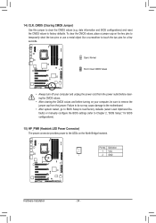
... to load factory defaults (select Load Optimized Defaults) or manually configure the BIOS settings (refer to remove the jumper cap from the power outlet before clearing the CMOS values. • After clearing the CMOS values and before turning on the North Bridge heatsink. Open: Normal... two pins or use a metal object like a screwdriver to touch the two pins for BIOS configurations). 15) HP_PWR (Heatsink LED Power Connector) The power connector provides power to the LEDs on your computer, be sure to Chapter 2, "BIOS Setup," for a few seconds. date information and BIOS configurations...
... to load factory defaults (select Load Optimized Defaults) or manually configure the BIOS settings (refer to remove the jumper cap from the power outlet before clearing the CMOS values. • After clearing the CMOS values and before turning on the North Bridge heatsink. Open: Normal... two pins or use a metal object like a screwdriver to touch the two pins for BIOS configurations). 15) HP_PWR (Heatsink LED Power Connector) The power connector provides power to the LEDs on your computer, be sure to Chapter 2, "BIOS Setup," for a few seconds. date information and BIOS configurations...

Manual
Page 35
...header connects to the Quick Boost button's cable from the battery holder and wait for 5 seconds.) 3. Hardware Installation 16) BAT (Battery) The battery provides power to a low level, or the CMOS values may not be accurate or may clear the CMOS values by your computer and unplug the... power cord. 2. Turn off your - You may be handled in the power cord and restart your computer. • Always turn off your computer and unplug the power cord before replacing the battery. • Replace the battery with an ...
...header connects to the Quick Boost button's cable from the battery holder and wait for 5 seconds.) 3. Hardware Installation 16) BAT (Battery) The battery provides power to a low level, or the CMOS values may not be accurate or may clear the CMOS values by your computer and unplug the... power cord. 2. Turn off your - You may be handled in the power cord and restart your computer. • Always turn off your computer and unplug the power cord before replacing the battery. • Replace the battery with an ...


