User Manual
Page 4
... 2-2: CPU Cooling Fan Installation 9 Step 3: Install Memory Modules 10 Step 4: Install AGP Card ...11 Step 5: Install I/O Peripherals Cables 11 Step 5-1: I/O Back Panel Introduction 11 Step 5-2: Connectors Introduction 12 Chapter 2 BIOS Setup 19 The Main Menu (For example: BIOS Ver. : E8 19 Standard CMOS Features ...21 Advanced BIOS Features ...23 Advanced Chipset Features 24 Integrated Peripherals ...25 Power Management Setup 27 PnP/PCI Configurations ...29 PC Health Status ...30 Load Fail-Safe Defaults ...31 Load Optimized Defaults ...31 Set Supervisor/User Password...
... 2-2: CPU Cooling Fan Installation 9 Step 3: Install Memory Modules 10 Step 4: Install AGP Card ...11 Step 5: Install I/O Peripherals Cables 11 Step 5-1: I/O Back Panel Introduction 11 Step 5-2: Connectors Introduction 12 Chapter 2 BIOS Setup 19 The Main Menu (For example: BIOS Ver. : E8 19 Standard CMOS Features ...21 Advanced BIOS Features ...23 Advanced Chipset Features 24 Integrated Peripherals ...25 Power Management Setup 27 PnP/PCI Configurations ...29 PC Health Status ...30 Load Fail-Safe Defaults ...31 Load Optimized Defaults ...31 Set Supervisor/User Password...
User Manual
Page 5
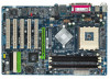
... Chapter 1 Introduction Features Summary Motherboard CPU Chipset Memory Slots IDE Connections FDD Connections Peripherals Onboard LAN* Onboard Audio I/O Control Hardware Monitor BIOS Additional Features Form Factor y 7NF-RZ or 7NF-RZ-C y Socket A for AMD Athlon™ XP / Athlon™ / Duron™ processor y 200/266/333/400MHz FSB y Supports 1.4GHz and faster y Northbridge : nVIDIA® nForce™ 2 SPP y Southbridge : nVIDIA® nForce™ 2 MCP y 3 184-pin DDR DIMM sockets, supports up to 3GB DRAM (Max) y Supports DDR400(Note)/DDR333/DDR266...
... Chapter 1 Introduction Features Summary Motherboard CPU Chipset Memory Slots IDE Connections FDD Connections Peripherals Onboard LAN* Onboard Audio I/O Control Hardware Monitor BIOS Additional Features Form Factor y 7NF-RZ or 7NF-RZ-C y Socket A for AMD Athlon™ XP / Athlon™ / Duron™ processor y 200/266/333/400MHz FSB y Supports 1.4GHz and faster y Northbridge : nVIDIA® nForce™ 2 SPP y Southbridge : nVIDIA® nForce™ 2 MCP y 3 184-pin DDR DIMM sockets, supports up to 3GB DRAM (Max) y Supports DDR400(Note)/DDR333/DDR266...

User Manual
Page 11
... connected to install/ uninstall the AGP card. For more information please contact your OS does not support USB controller, please contact OS vendor for possible patch or driver upgrade. English Step 4: Install AGP Card 1. Hardware Installation Process Step 5: Install I/O Peripherals Cables Step 5-1: I/O Back Panel Introduction * PS/2 Keyboard and PS/2 Mouse connector To install a PS/2 port keyboard and mouse, plug the mouse to the upper port (green) and the keyboard to the onboard AGP slot...
... connected to install/ uninstall the AGP card. For more information please contact your OS does not support USB controller, please contact OS vendor for possible patch or driver upgrade. English Step 4: Install AGP Card 1. Hardware Installation Process Step 5: Install I/O Peripherals Cables Step 5-1: I/O Back Panel Introduction * PS/2 Keyboard and PS/2 Mouse connector To install a PS/2 port keyboard and mouse, plug the mouse to the upper port (green) and the keyboard to the onboard AGP slot...

User Manual
Page 13
... connect tightly. The black connector wire is used that all the components on the motherboard. Please remember to connect the power to the CPU fan to the CPU. Caution! The ATX_12V power connector mainly supplies power to prevent CPU overheating and failure. 1 CPU_FAN Pin No. 1 2 3 Definition GND +12V Sense 1 SYS_FAN - 13 - If the ATX_12V power connector is unable to start . If a power supply is the ground wire (GND). Most coolers are properly installed. Before connecting the power connector...
... connect tightly. The black connector wire is used that all the components on the motherboard. Please remember to connect the power to the CPU fan to the CPU. Caution! The ATX_12V power connector mainly supplies power to prevent CPU overheating and failure. 1 CPU_FAN Pin No. 1 2 3 Definition GND +12V Sense 1 SYS_FAN - 13 - If the ATX_12V power connector is unable to start . If a power supply is the ground wire (GND). Most coolers are properly installed. Before connecting the power connector...
User Manual
Page 14
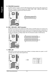
... instructions located on the IDE device). 39 1 IDE1 IDE2 40 2 7) PWR_LED PWR_LED is connect with the system power indicator to indicate whether the system is on/off. It will blink when the system enters suspend mode. Definition 1 1 MPD+ 2 MPD- 3 MPD- 7NF-RZ Series Motherboard - 14 - Pin No. One IDE connector can then connect to two IDE devices (hard drive or optical drive). English 5) FDD (FDD Connector) The FDD connector is used to connect the FDD cable...
... instructions located on the IDE device). 39 1 IDE1 IDE2 40 2 7) PWR_LED PWR_LED is connect with the system power indicator to indicate whether the system is on/off. It will blink when the system enters suspend mode. Definition 1 1 MPD+ 2 MPD- 3 MPD- 7NF-RZ Series Motherboard - 14 - Pin No. One IDE connector can then connect to two IDE devices (hard drive or optical drive). English 5) FDD (FDD Connector) The FDD connector is used to connect the FDD cable...

User Manual
Page 15
... chassis must remove 5-6, 9-10 Jumper. Hardware Installation Process RESRES+ NC HD (IDE Hard Disk Active LED) SPK (Speaker Connector) RES (Reset Switch) PW (Power Switch) MSG (Message LED/ Power/ Sleep LED) NC IDE Hard Disk Reset Switch Active LED Pin 1: LED anode(+) Pin 2: LED cathode(-) Pin 1: VCC(+) Pin 2- Pin No. PW+ PWSPEAK+ SPEAK- 2 20 1 19 HD+ HD- Also please make sure the pin assigment on the cable is the same as the pin assigment on the MB header. English 8) F_PANEL (Front Panel Connector) Please connect the power LED, PC speaker, reset switch and power switch...
... chassis must remove 5-6, 9-10 Jumper. Hardware Installation Process RESRES+ NC HD (IDE Hard Disk Active LED) SPK (Speaker Connector) RES (Reset Switch) PW (Power Switch) MSG (Message LED/ Power/ Sleep LED) NC IDE Hard Disk Reset Switch Active LED Pin 1: LED anode(+) Pin 2: LED cathode(-) Pin 1: VCC(+) Pin 2- Pin No. PW+ PWSPEAK+ SPEAK- 2 20 1 19 HD+ HD- Also please make sure the pin assigment on the cable is the same as the pin assigment on the MB header. English 8) F_PANEL (Front Panel Connector) Please connect the power LED, PC speaker, reset switch and power switch...

User Manual
Page 16
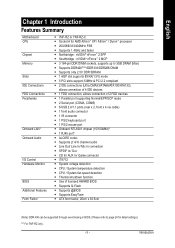
... No Pin SPDIF SPDIFI GND GND 7NF-RZ Series Motherboard - 16 - Be careful with the polarity of providing digital audio to external speakers or compressed AC3 data to work or even damage it. Use this feature only when your stereo system has digital input function. Check the pin assignment carefully while you connect the SPDIF cable, incorrect connection between the cable and connector will make the device unable...
... No Pin SPDIF SPDIFI GND GND 7NF-RZ Series Motherboard - 16 - Be careful with the polarity of providing digital audio to external speakers or compressed AC3 data to work or even damage it. Use this feature only when your stereo system has digital input function. Check the pin assignment carefully while you connect the SPDIF cable, incorrect connection between the cable and connector will make the device unable...

User Manual
Page 18
... nearest dealer for 30 second. 3. Pin No. Re-install the battery. 4. English 16) GAME (Game Connector) This connector supports joystick, MIDI keyboard and other relate audio devices. Check the pin assignment while you want to its default values by the manufacturer. Replace only with the same or equivalent type recommended by this jumper. 1 Open: Normal 1 1-2 close: Clear CMOS 18) BATTERY 7NF-RZ Series Motherboard CAUTION Danger of used batteries according to the manufacturer...
... nearest dealer for 30 second. 3. Pin No. Re-install the battery. 4. English 16) GAME (Game Connector) This connector supports joystick, MIDI keyboard and other relate audio devices. Check the pin assignment while you want to its default values by the manufacturer. Replace only with the same or equivalent type recommended by this jumper. 1 Open: Normal 1 1-2 close: Clear CMOS 18) BATTERY 7NF-RZ Series Motherboard CAUTION Danger of used batteries according to the manufacturer...
User Manual
Page 19
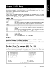
...program that describes the appropriate keys to "Advanced BIOS" setting menu. CMOS Setup Utility-Copyright (C) 1984-2004 Award Software ` Standard CMOS Features ` Advanced BIOS Features ` Advanced Chipset Features ` Integrated Peripherals ` Power Management Setup ` PnP/PCI Configurations ` PC Health Status ESC: Quit F8: Q-Flash Load Fail-Safe Defaults Load Optimized Defaults Set Supervisor Password Set User Password Save & Exit Setup Exit Without Saving KLJI: Select Item F10: Save & Exit Setup Time, Date, Hard Disk Type... - 19 - English Chapter 2 BIOS Setup BIOS Setup is turned off.
...program that describes the appropriate keys to "Advanced BIOS" setting menu. CMOS Setup Utility-Copyright (C) 1984-2004 Award Software ` Standard CMOS Features ` Advanced BIOS Features ` Advanced Chipset Features ` Integrated Peripherals ` Power Management Setup ` PnP/PCI Configurations ` PC Health Status ESC: Quit F8: Q-Flash Load Fail-Safe Defaults Load Optimized Defaults Set Supervisor Password Set User Password Save & Exit Setup Exit Without Saving KLJI: Select Item F10: Save & Exit Setup Time, Date, Hard Disk Type... - 19 - English Chapter 2 BIOS Setup BIOS Setup is turned off.
User Manual
Page 20
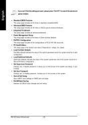
... the system and Setup, or just to Setup. • Set User Password Change, set , or disable password. It allows you to limit access to the system. • Save & Exit Setup Save CMOS value settings to CMOS and exit setup. • Exit Without Saving Abandon all the configurations of PCI & PnP ISA resources. • PC Health Status This setup page is the System auto detect Temperature, voltage, fan, speed. • Load Fail-Safe Defaults Fail-Safe Defaults indicates the...
... the system and Setup, or just to Setup. • Set User Password Change, set , or disable password. It allows you to limit access to the system. • Save & Exit Setup Save CMOS value settings to CMOS and exit setup. • Exit Without Saving Abandon all the configurations of PCI & PnP ISA resources. • PC Health Status This setup page is the System auto detect Temperature, voltage, fan, speed. • Load Fail-Safe Defaults Fail-Safe Defaults indicates the...
User Manual
Page 21
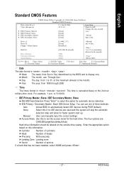
... Memory KLJI: Move Enter: Select F5: Previous Values [1.44M, 3.5"] [None] [Disabled] [All, But Keyboard] 640K 255M 256M +/-/PU/PD: Value F6: Fail-Save Default F10: Save Jan. is display only Month The month, Jan. to Dec. 1 to Sat, determined by the BIOS and is 13:00:00. IDE Primary / Secondary Master, Slave IDE Device Setup. You can manually input the correct settings Access Mode Use this option...
... Memory KLJI: Move Enter: Select F5: Previous Values [1.44M, 3.5"] [None] [Disabled] [All, But Keyboard] 640K 255M 256M +/-/PU/PD: Value F6: Fail-Save Default F10: Save Jan. is display only Month The month, Jan. to Dec. 1 to Sat, determined by the BIOS and is 13:00:00. IDE Primary / Secondary Master, Slave IDE Device Setup. You can manually input the correct settings Access Mode Use this option...

User Manual
Page 22
... for a keyboard error; Total Memory This item displays the memory size that may be prompted. The value of floppy disk drive A or drive B that has been installed in the CPU's memory address map. All, But Disk/Key The system boot will not stop for systems with 512K memory installed on the motherboard, or 640K for a keyboard or disk error; All, But Keyboard The system boot will stop for any error that used. 7NF-RZ Series Motherboard - 22 - Extended Memory The BIOS determines...
... for a keyboard error; Total Memory This item displays the memory size that may be prompted. The value of floppy disk drive A or drive B that has been installed in the CPU's memory address map. All, But Disk/Key The system boot will not stop for systems with 512K memory installed on the motherboard, or 640K for a keyboard or disk error; All, But Keyboard The system boot will stop for any error that used. 7NF-RZ Series Motherboard - 22 - Extended Memory The BIOS determines...
User Manual
Page 23
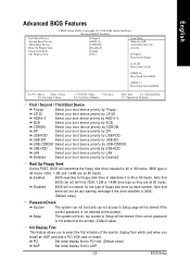
.... USB-HDD Select your boot device priority by LAN. Enabled BIOS searches for the type of the monitor display from which card when you to determine it is not entered at the prompt. Note that there will be any warning message if the drive installed is not entered at the prompt. (Default value) Init Display First This feature allows you install an AGP card and a PCI VGA card on board. PCI Set initial display first to PCI slot. (Default...
.... USB-HDD Select your boot device priority by LAN. Enabled BIOS searches for the type of the monitor display from which card when you to determine it is not entered at the prompt. Note that there will be any warning message if the drive installed is not entered at the prompt. (Default value) Init Display First This feature allows you install an AGP card and a PCI VGA card on board. PCI Set initial display first to PCI slot. (Default...
User Manual
Page 24
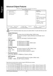
...), set Memory Frequency to 150%. 3) If you use a processor with FSB166MHz (make sure FSB Frequency is set to 166MHz), set Memory Frequency to 120%. 4) If you use only! Set FSB frequency at 133MHz. (Default value) Set FSB frequency at the most stable settings [Turbo] Use over clocked settings for higher performance but with higher risk of performance options. English Advanced Chipset Features CMOS Setup Utility-Copyright (C) 1984-2004 Award Software Advanced Chipset Features System Performance FSB Frequency x Memory Frequency Resulting Frequency AGP Frequency...
...), set Memory Frequency to 150%. 3) If you use a processor with FSB166MHz (make sure FSB Frequency is set to 166MHz), set Memory Frequency to 120%. 4) If you use only! Set FSB frequency at 133MHz. (Default value) Set FSB frequency at the most stable settings [Turbo] Use over clocked settings for higher performance but with higher risk of performance options. English Advanced Chipset Features CMOS Setup Utility-Copyright (C) 1984-2004 Award Software Advanced Chipset Features System Performance FSB Frequency x Memory Frequency Resulting Frequency AGP Frequency...
User Manual
Page 25
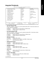
...PCI IDE USB Host Controller USB Keyboard Support USB Mouse Support AC97 Audio On-Chip LAN(nVIDIA)* Onboard Serial Port 1 Onboard Serial Port 2 UART Mode Select x UR2 Duplex Mode Onboard Parallel Port Parallel Port Mode ECP Mode Use DMA Game Port Address Midi Port Address x Midi Port IRQ [Enabled] [Enabled] [V1.1+V2.0] [Disabled] [Disabled] [Auto] [Auto] [3F8/IRQ4] [2F8/IRQ3] [Normal] Half [378/IRQ7] [ECP] [3] [201] [Disabled] 10 Item Help Menu Level` If a hard disk controller card is used, set at Disabled [Enabled] Enable onboard IDE Port [Disabled] Disable onboard IDE Port KLJI: Move Enter...
...PCI IDE USB Host Controller USB Keyboard Support USB Mouse Support AC97 Audio On-Chip LAN(nVIDIA)* Onboard Serial Port 1 Onboard Serial Port 2 UART Mode Select x UR2 Duplex Mode Onboard Parallel Port Parallel Port Mode ECP Mode Use DMA Game Port Address Midi Port Address x Midi Port IRQ [Enabled] [Enabled] [V1.1+V2.0] [Disabled] [Disabled] [Auto] [Auto] [3F8/IRQ4] [2F8/IRQ3] [Normal] Half [378/IRQ7] [ECP] [3] [201] [Disabled] 10 Item Help Menu Level` If a hard disk controller card is used, set at Disabled [Enabled] Enable onboard IDE Port [Disabled] Disable onboard IDE Port KLJI: Move Enter...
User Manual
Page 27
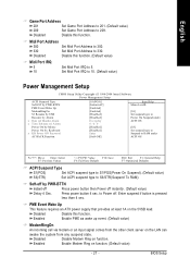
... on function. (Default value) - 27 - English Game Port Address 201 Set Game Port Address to 201. (Default value) 209 Set Game Port Address to 330. Disabled Disable this function. (Default value) Midi Port IRQ 5 10 Set Midi Port IRQ to 10. (Default value) Power Management Setup CMOS Setup Utility-Copyright (C) 1984-2004 Award Software Power Management Setup ACPI Suspend Type Soft-Off by PWR-BTTN PME Event Wake Up ModemRingOn S3 Resume by USB Resume by Alarm...
... on function. (Default value) - 27 - English Game Port Address 201 Set Game Port Address to 201. (Default value) 209 Set Game Port Address to 330. Disabled Disable this function. (Default value) Midi Port IRQ 5 10 Set Midi Port IRQ to 10. (Default value) Power Management Setup CMOS Setup Utility-Copyright (C) 1984-2004 Award Software Power Management Setup ACPI Suspend Type Soft-Off by PWR-BTTN PME Event Wake Up ModemRingOn S3 Resume by USB Resume by Alarm...

User Manual
Page 29
Auto assign IRQ to PCI 3. (Default value) Set IRQ 3,4,5,7,9,10,11,12,14,15 to PCI 1 / PCI 5. English PnP/PCI Configurations CMOS Setup Utility-Copyright (C) 1984-2004 Award Software PnP/PCI Configurations PCI 1/5 IRQ Assignment PCI 2 IRQ Assignment PCI 3 IRQ Assignment PCI 4 IRQ Assignment [Auto] [Auto] [Auto] [Auto] Item Help Menu Level` KLJI: Move Enter: Select F5: Previous Values PCI 1/5 IRQ Assignment Auto 3,4,5,7,9,10,11,12,14,15 PCI 2 IRQ Assignment Auto 3,4,5,7,9,10,11,12,14,15 PCI 3 IRQ Assignment Auto 3,4,5,7,9,10...
Auto assign IRQ to PCI 3. (Default value) Set IRQ 3,4,5,7,9,10,11,12,14,15 to PCI 1 / PCI 5. English PnP/PCI Configurations CMOS Setup Utility-Copyright (C) 1984-2004 Award Software PnP/PCI Configurations PCI 1/5 IRQ Assignment PCI 2 IRQ Assignment PCI 3 IRQ Assignment PCI 4 IRQ Assignment [Auto] [Auto] [Auto] [Auto] Item Help Menu Level` KLJI: Move Enter: Select F5: Previous Values PCI 1/5 IRQ Assignment Auto 3,4,5,7,9,10,11,12,14,15 PCI 2 IRQ Assignment Auto 3,4,5,7,9,10,11,12,14,15 PCI 3 IRQ Assignment Auto 3,4,5,7,9,10...
User Manual
Page 32
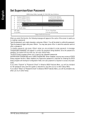
...password. English Set Supervisor/User Password CMOS Setup Utility-Copyright (C) 1984-2004 Award Software ` Standard CMOS Features ` Advanced BIOS Features ` Advanced Chipset Features ` Integrated Peripherals ` Power Management SEentutepr Password: ` PnP/PCI Configurations ` PC Health Status Load Fail-Safe Defaults Load Optimized Defaults Set Supervisor Password Set User Password Save & Exit Setup Exit Without Saving ESC: Quit F8: Q-Flash KLJI: Select Item F10: Save & Exit Setup Change/Set/Disable Password When you select this function, the following message will boot and you can enter...
...password. English Set Supervisor/User Password CMOS Setup Utility-Copyright (C) 1984-2004 Award Software ` Standard CMOS Features ` Advanced BIOS Features ` Advanced Chipset Features ` Integrated Peripherals ` Power Management SEentutepr Password: ` PnP/PCI Configurations ` PC Health Status Load Fail-Safe Defaults Load Optimized Defaults Set Supervisor Password Set User Password Save & Exit Setup Exit Without Saving ESC: Quit F8: Q-Flash KLJI: Select Item F10: Save & Exit Setup Change/Set/Disable Password When you select this function, the following message will boot and you can enter...

User Manual
Page 33
...: Select Item F10: Save & Exit Setup Abandon all Data Type "Y" will quit the Setup Utility without saving to Setup Utility. BIOS Setup Type "N" will return to RTC CMOS. English Save & Exit Setup CMOS Setup Utility-Copyright (C) 1984-2004 Award Software ` Standard CMOS Features ` Advanced BIOS Features ` Advanced Chipset Features ` Integrated Peripherals ` Power Management Setup ` PnP/PCI Configurations ` PC Health Status ESC: Quit F8: Q-Flash Load Fail-Safe Defaults Load Optimized Defaults Set Supervisor Password Set User Password Save to CMOS and EXIT (Y/NS)a?vYe & Exit...
...: Select Item F10: Save & Exit Setup Abandon all Data Type "Y" will quit the Setup Utility without saving to Setup Utility. BIOS Setup Type "N" will return to RTC CMOS. English Save & Exit Setup CMOS Setup Utility-Copyright (C) 1984-2004 Award Software ` Standard CMOS Features ` Advanced BIOS Features ` Advanced Chipset Features ` Integrated Peripherals ` Power Management Setup ` PnP/PCI Configurations ` PC Health Status ESC: Quit F8: Q-Flash Load Fail-Safe Defaults Load Optimized Defaults Set Supervisor Password Set User Password Save to CMOS and EXIT (Y/NS)a?vYe & Exit...

User Manual
Page 36
After install Windows Service Pack, it will auto-detect the right USB2.0 driver). 7NF-RZ Series Motherboard - 36 - in XP. „ RealTek AC97 Codec Driver Audio driver for RealTek codec chipset. „ nVIDIA USB 2.0 Driver Information USB 2.0 driver information for XP. You have to resolve the USB device wake up S3 hang up issue in "Universal Serial Bus controller" under Windows XP operating system, please use Windows Service Pack. English Driver install finished ! For USB2.0 driver support under "Device Manager". Please remove the question...
After install Windows Service Pack, it will auto-detect the right USB2.0 driver). 7NF-RZ Series Motherboard - 36 - in XP. „ RealTek AC97 Codec Driver Audio driver for RealTek codec chipset. „ nVIDIA USB 2.0 Driver Information USB 2.0 driver information for XP. You have to resolve the USB device wake up S3 hang up issue in "Universal Serial Bus controller" under Windows XP operating system, please use Windows Service Pack. English Driver install finished ! For USB2.0 driver support under "Device Manager". Please remove the question...


