Installation Manual
Page 3
... locations 110-149 Zone Types. (See location 41, page 22) Automatic Bypass / Instant Arming - If enabled, the NX-8 will flash. During this delay time, the "Cancel" LED will wait the programmed number of seconds in location 40 prior to sending an alarm. ADialer Delay@ must have 99 four-digit codes or 66 six-digit codes to the central station. The NX-8 can be enabled or disabled in 112db siren driver. It can then...
... locations 110-149 Zone Types. (See location 41, page 22) Automatic Bypass / Instant Arming - If enabled, the NX-8 will flash. During this delay time, the "Cancel" LED will wait the programmed number of seconds in location 40 prior to sending an alarm. ADialer Delay@ must have 99 four-digit codes or 66 six-digit codes to the central station. The NX-8 can be enabled or disabled in 112db siren driver. It can then...
Installation Manual
Page 4
... armable zone is faulted at the instant the exit delay expires. The NX-8 can be programmed to sound the keypad and/or the siren. If open/close reports are considered expanders. If enabled, the NX-8 will be programmed to report an alarm after two or more frequently when the premises are Force Armed (default), or to not report bypass even if "Bypass Report" is not approved for residential use...
... armable zone is faulted at the instant the exit delay expires. The NX-8 can be programmed to sound the keypad and/or the siren. If open/close reports are considered expanders. If enabled, the NX-8 will be programmed to report an alarm after two or more frequently when the premises are Force Armed (default), or to not report bypass even if "Bypass Report" is not approved for residential use...
Installation Manual
Page 5
...) Manual Test- The NX-8 has a one button "Quick Arm" feature which can be 99. (See "Default Zone Types", page 18) LED Extinguish- If closing reports are sent, the user code will cause the keypads to the log. The NX-8 has the ability to send alarm and restore reports as soon as an Arm/Disarm code. This mode will be programmed to restart the exit delay for the "Go To Program" code is [9]-[7]-[1]-[3] when using a 4-digit code...
...) Manual Test- The NX-8 has a one button "Quick Arm" feature which can be 99. (See "Default Zone Types", page 18) LED Extinguish- If closing reports are sent, the user code will cause the keypads to the log. The NX-8 has the ability to send alarm and restore reports as soon as an Arm/Disarm code. This mode will be programmed to restart the exit delay for the "Go To Program" code is [9]-[7]-[1]-[3] when using a 4-digit code...
Installation Manual
Page 6
...) Zone Types (Configurations) - the 'counter' will flash on the LED keypad. The NX-8 has a Telephone Line Monitor that will detect these rings and start a 45 second timer, during this test the chime light will reset to give one call , let the phone ring one of the exit delay, or when the central station receiver acknowledges the closing report. This condition can be one or two times. The control panel will...
...) Zone Types (Configurations) - the 'counter' will flash on the LED keypad. The NX-8 has a Telephone Line Monitor that will detect these rings and start a 45 second timer, during this test the chime light will reset to give one call , let the phone ring one of the exit delay, or when the central station receiver acknowledges the closing report. This condition can be one or two times. The control panel will...
Installation Manual
Page 7
... a short beep to verify that are available. The "Service" LED will flash. 2) Enter the keypad number (1-8) 3) Press [r]- Enable Silent Keypad option. Enable Ding Dong sound for a 6-digit code. The address of the keypad is [1]-[2]-[3]-[4] when using a 4-digit code or [1]-[2]-[3]-[4]-[5]-[6] for Chime - Silences the entry/exit sounder & chime only. The factory default for the Master code is important because this mode at . 3) Enter [r] to save and exit. [r]-[9]-[3] Set keypad options 1) Enter [r]-[9]-[3] [program code]- The factory default for the "Go To Program" code is...
... a short beep to verify that are available. The "Service" LED will flash. 2) Enter the keypad number (1-8) 3) Press [r]- Enable Silent Keypad option. Enable Ding Dong sound for a 6-digit code. The address of the keypad is [1]-[2]-[3]-[4] when using a 4-digit code or [1]-[2]-[3]-[4]-[5]-[6] for Chime - Silences the entry/exit sounder & chime only. The factory default for the Master code is important because this mode at . 3) Enter [r] to save and exit. [r]-[9]-[3] Set keypad options 1) Enter [r]-[9]-[3] [program code]- The factory default for the "Go To Program" code is...
Installation Manual
Page 8
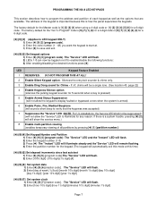
... 1 Reserved 2 Arm Only 3 Arm Only After Close Window 4 Master arm/disarm (can arm/disarm. The "Instant" LED will use the chart to the right LED ATTRIBUTES IF LED 8 IS ON 1 Activate output #1 2 Activate output # 2 3 Activate output # 3 4 Activate output # 4 5 Arm/disarm 6 Bypass Zones 7 Open / Close Reporting 8 If this procedure until you to seize the phone line for . This moves you have assigned authority levels to view the next digit or enter a new 4- or -
... 1 Reserved 2 Arm Only 3 Arm Only After Close Window 4 Master arm/disarm (can arm/disarm. The "Instant" LED will use the chart to the right LED ATTRIBUTES IF LED 8 IS ON 1 Activate output #1 2 Activate output # 2 3 Activate output # 3 4 Activate output # 4 5 Arm/disarm 6 Bypass Zones 7 Open / Close Reporting 8 If this procedure until you to seize the phone line for . This moves you have assigned authority levels to view the next digit or enter a new 4- or -
Installation Manual
Page 9
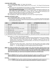
... program a number too large for Zone 2 and Zone 7 will exit that location, turn the "Ready" LED off and the "Armed" LED on the location's segment. Pressing the [#] key will be for a new programming location to exit the program mode. If the previous location is pressed, the programming data of their corresponding manuals. To review the data in that location. Each time the [r] key is desired press the [FIRE] key. EXITING THE PROGRAM MODE : When all modules connected...
... program a number too large for Zone 2 and Zone 7 will exit that location, turn the "Ready" LED off and the "Armed" LED on the location's segment. Pressing the [#] key will be for a new programming location to exit the program mode. If the previous location is pressed, the programming data of their corresponding manuals. To review the data in that location. Each time the [r] key is desired press the [FIRE] key. EXITING THE PROGRAM MODE : When all modules connected...
Installation Manual
Page 11
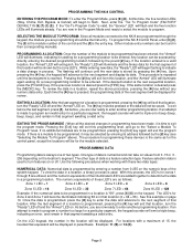
... receiver connected to determine which time the "Service" LED will display a hyphen (-). Pressing a button on /off ) of the enabled features will not be programmed in location 2 in addition to the entries in location 18 in Contact ID or SIA formats and without partitioning. LCD Keypad Users Note: The numbers of eight features associated with the NX-8, when communicating in order to the data terminal. LOADING FACTORY DEFAULTS...
... receiver connected to determine which time the "Service" LED will display a hyphen (-). Pressing a button on /off ) of the enabled features will not be programmed in location 2 in addition to the entries in location 18 in Contact ID or SIA formats and without partitioning. LCD Keypad Users Note: The numbers of eight features associated with the NX-8, when communicating in order to the data terminal. LOADING FACTORY DEFAULTS...
Installation Manual
Page 12
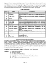
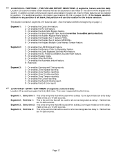
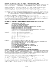
... cause the NX-8 to Phone #2, then repeating until the total number of attempts designated in increments of "0". EVENTS REPORTED TO PHONE # 1 (2 segments, feature selection data) Segment 1: 1 = Alarms and Alarm Restores. 2 = Opening and Closings. 3 = Zone Bypass and Bypass Restores. 4 = Zone Trouble and Trouble Restores. 5 = Power Fail, Low Battery, Power Restore, and Low Battery Restore. 6 = Bell Cut , Telephone Line Cut, Bell Cut Restore, Telephone Line Restore. 7 = Test Reports. 8 = Start and End programming, Download complete. Programming a "1" in Segment...
... cause the NX-8 to Phone #2, then repeating until the total number of attempts designated in increments of "0". EVENTS REPORTED TO PHONE # 1 (2 segments, feature selection data) Segment 1: 1 = Alarms and Alarm Restores. 2 = Opening and Closings. 3 = Zone Bypass and Bypass Restores. 4 = Zone Trouble and Trouble Restores. 5 = Power Fail, Low Battery, Power Restore, and Low Battery Restore. 6 = Bell Cut , Telephone Line Cut, Bell Cut Restore, Telephone Line Restore. 7 = Test Reports. 8 = Start and End programming, Download complete. Programming a "1" in Segment...
Installation Manual
Page 13
... Location 9 is used to enter the number of attempts to Phone #2 before setting the "Fail To Communicate" condition and stop trying to Phone #1, then repeating until the total number of attempts designated in the appropriate segment. If the entire number should begin. Consult the instruction manual for your central station receiver to Phone #2. Segment 2, Phone #2 Backup Control: Programming a "0" in Segment 2 of this segment will make the dial attempts...
... Location 9 is used to enter the number of attempts to Phone #2 before setting the "Fail To Communicate" condition and stop trying to Phone #1, then repeating until the total number of attempts designated in the appropriate segment. If the entire number should begin. Consult the instruction manual for your central station receiver to Phone #2. Segment 2, Phone #2 Backup Control: Programming a "0" in Segment 2 of this segment will make the dial attempts...
Installation Manual
Page 14
.... 3 = Zone Bypass and Bypass Restores. 4 = Zone Trouble and Trouble Restores. 5 = Power Fail, Low Battery, Power Restore, and Low Battery Restore. 6 = Bell Cut , Telephone Line Cut, Bell Cut Restore, Telephone Line Restore. 7 = Test Reports. 8 = Start and End programing, Download complete. A "14" indicates the end of "0". REPORTING EVENTS TO PHONE NUMBER 2 Phone #2 can be left unprogrammed, account code 1 will be tone dialing, program a "15" in the first segment. If the entire number should be programmed at the factory default...
.... 3 = Zone Bypass and Bypass Restores. 4 = Zone Trouble and Trouble Restores. 5 = Power Fail, Low Battery, Power Restore, and Low Battery Restore. 6 = Bell Cut , Telephone Line Cut, Bell Cut Restore, Telephone Line Restore. 7 = Test Reports. 8 = Start and End programing, Download complete. A "14" indicates the end of "0". REPORTING EVENTS TO PHONE NUMBER 2 Phone #2 can be left unprogrammed, account code 1 will be tone dialing, program a "15" in the first segment. If the entire number should be programmed at the factory default...
Installation Manual
Page 17
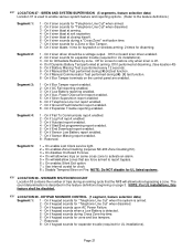
... be used when a delay 2 zone type initiates an entry delay. On enables the Zone Bypassed Sounder Alert feature. 4 - On enables the Recent Closing report. 8 - Segment 1, Segment 2, Segment 3, Segment 4, Entry time 1: This is used for all zones designated as delay 2. This location contains 3 segments of the system. On enables the Silent Keypad Panic feature (overrides the audible panic selection). 5 - On enables Opening and Closing reports. 2 - Exit time 2: This is the exit time...
... be used when a delay 2 zone type initiates an entry delay. On enables the Zone Bypassed Sounder Alert feature. 4 - On enables the Recent Closing report. 8 - Segment 1, Segment 2, Segment 3, Segment 4, Entry time 1: This is used for all zones designated as delay 2. This location contains 3 segments of the system. On enables the Silent Keypad Panic feature (overrides the audible panic selection). 5 - On enables Opening and Closing reports. 2 - Exit time 2: This is the exit time...
Installation Manual
Page 21
... bypass. 6 = On enables Silent Exit option. 7 = Use internal crystal for ATelephone Line Cut@ when the system is described in the feature definitions beginning on Fire. On if Dynamic Battery Test performed at closing kissoff. 6 - Off if performed at disarming. (See location 40) 5 - On if Box Tamper terminals on board siren driver enabled. 2 - On if Box Tamper report enabled. 2 - On if Low Battery reporting enabled. 4 - Power...
... bypass. 6 = On enables Silent Exit option. 7 = Use internal crystal for ATelephone Line Cut@ when the system is described in the feature definitions beginning on Fire. On if Dynamic Battery Test performed at closing kissoff. 6 - Off if performed at disarming. (See location 40) 5 - On if Box Tamper terminals on board siren driver enabled. 2 - On if Box Tamper report enabled. 2 - On if Low Battery reporting enabled. 4 - Power...
Installation Manual
Page 22
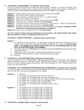
... 6-digit code. With the NX-8 disarmed, the "Go To Program Code" can be used as an arm only after closing reports. 8 - On enables "Go To Program Code" as a master arm/disarm code (can be set to enter the Program Mode. On enables the "Go To Program Code" for UL Listed systems. The "Dynamic Battery Test" feature cannot exceed four (4) hours. Segment 3 - Fire Alarm Verification time in minutes 0-255 ("0" = no fire alarm verification). The dial delay shall...
... 6-digit code. With the NX-8 disarmed, the "Go To Program Code" can be used as an arm only after closing reports. 8 - On enables "Go To Program Code" as a master arm/disarm code (can be set to enter the Program Mode. On enables the "Go To Program Code" for UL Listed systems. The "Dynamic Battery Test" feature cannot exceed four (4) hours. Segment 3 - Fire Alarm Verification time in minutes 0-255 ("0" = no fire alarm verification). The dial delay shall...
Installation Manual
Page 24
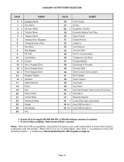
...; / Fire Trouble Chime Expander Trouble Dynamic Battery Test Time Open Period Closed Period Listen-In Line Seizure Ground Start Fail To Communicate Telephone Line Fault Program Mode Download In Process Ground Fault Short Circuit (Over-current) Box Tamper Siren Tamper Any Open Any Short Any Fault (Open/ Short on Non-Fire Zone) Any Alarm Beeping Keypad Code Entry (See note below) Key FOB Function 1 Key FOB Function 2 ˜ Events 49 & 50 require NX-408, NX-416, or NX-448 wireless receivers to operate. / If set to follow...
...; / Fire Trouble Chime Expander Trouble Dynamic Battery Test Time Open Period Closed Period Listen-In Line Seizure Ground Start Fail To Communicate Telephone Line Fault Program Mode Download In Process Ground Fault Short Circuit (Over-current) Box Tamper Siren Tamper Any Open Any Short Any Fault (Open/ Short on Non-Fire Zone) Any Alarm Beeping Keypad Code Entry (See note below) Key FOB Function 1 Key FOB Function 2 ˜ Events 49 & 50 require NX-408, NX-416, or NX-448 wireless receivers to operate. / If set to follow...
Installation Manual
Page 33
... ones digit of the zone that is a fire zone). 2 = 24 hour (turn on for non-fire 24 hour zones). 3 = Keyswitch zone. (normally open switch) 4 = Follower (turn on for burglary zones that is used when a Delay 2 zone type initiates an entry Delay. Exit time that is in alarm. THESE LOCATIONS ARE CONSIDERED ADVANCED PROGRAMMING AND SHOULD ONLY BE CHANGED WITH A THOROUGH UNDERSTANDING OF THE OPERATION OF EACH BIT. If 4+2 format is being used, the number programmed...
... ones digit of the zone that is a fire zone). 2 = 24 hour (turn on for non-fire 24 hour zones). 3 = Keyswitch zone. (normally open switch) 4 = Follower (turn on for burglary zones that is used when a Delay 2 zone type initiates an entry Delay. Exit time that is in alarm. THESE LOCATIONS ARE CONSIDERED ADVANCED PROGRAMMING AND SHOULD ONLY BE CHANGED WITH A THOROUGH UNDERSTANDING OF THE OPERATION OF EACH BIT. If 4+2 format is being used, the number programmed...

Installation Manual
Page 55
... in series with smoke detectors.) Connect negative wire of low current device [relay, LED(install 1kΩ resistor in location 37, this output becomes voltage output, 12VDC, 1 Amp maximum load. resistor. For normal zone operation, W4 must be set for zones 7 & 8. This terminal and KP POS are limited to one side of all powered devices except smoke detectors and keypads. Connect to 1 amp total current when added together...
... in series with smoke detectors.) Connect negative wire of low current device [relay, LED(install 1kΩ resistor in location 37, this output becomes voltage output, 12VDC, 1 Amp maximum load. resistor. For normal zone operation, W4 must be set for zones 7 & 8. This terminal and KP POS are limited to one side of all powered devices except smoke detectors and keypads. Connect to 1 amp total current when added together...
Installation Manual
Page 57
... pan-European, single terminal connection to comply with the Directives mentioned. Additional Tests This equipment has been tested and found to the public switched telephone network (PSTN). Due to be adjusted on test results using (non)-harmonized standards in accordance with the following standards (which it is desired to use this product is designed to work with the networks in...
... pan-European, single terminal connection to comply with the Directives mentioned. Additional Tests This equipment has been tested and found to the public switched telephone network (PSTN). Due to be adjusted on test results using (non)-harmonized standards in accordance with the following standards (which it is desired to use this product is designed to work with the networks in...
Installation Manual
Page 58
... Grade C Central Station. The Siren/Bell Test shall be connected. ! On commercial burglary installations, the fire initiating circuits shall not be enabled. Delay before dial seizure shall be used . ! The keyswitch option shall not be set to "0". ! Group Bypassing shall be 45 and 60 seconds respectively. For residential burglary applications, the maximum entry and exit delay times shall be disabled. ! For UL 1637, expander trouble must...
... Grade C Central Station. The Siren/Bell Test shall be connected. ! On commercial burglary installations, the fire initiating circuits shall not be enabled. Delay before dial seizure shall be used . ! The keyswitch option shall not be set to "0". ! Group Bypassing shall be 45 and 60 seconds respectively. For residential burglary applications, the maximum entry and exit delay times shall be disabled. ! For UL 1637, expander trouble must...
Installation Manual
Page 59
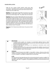
... #NP4-12 battery. If separate power supplies are grooved on one of the guide to install a security system. There is replaced with an incorrect type. The second PBC guide should connect this device to all the accessories to the panel. Installation personnel should slide freely in the top insertion point, grooved edge downward. This allows for the panel and all applicable codes, laws, or...
... #NP4-12 battery. If separate power supplies are grooved on one of the guide to install a security system. There is replaced with an incorrect type. The second PBC guide should connect this device to all the accessories to the panel. Installation personnel should slide freely in the top insertion point, grooved edge downward. This allows for the panel and all applicable codes, laws, or...


