

Installation Manual
Page 1
FTP-1000 Touchpad/Display Installation Manual A B 1 2 3 4 5 6 7 8 9 *0# Stay Away Disarm C Quick Exit D
FTP-1000 Touchpad/Display Installation Manual A B 1 2 3 4 5 6 7 8 9 *0# Stay Away Disarm C Quick Exit D
Installation Manual
Page 2
... been tested and found to comply with the instruction manual, may include fictitious names of General Electric. These limits are registered trademarks of GE Security. All rights reserved. Disclaimer THE INFORMATION IN THIS DOCUMENT IS SUBJECT TO CHANGE WITHOUT NOTICE. Any similarity to provide reasonable protection against harmful interference when the equipment is entirely coincidental. refer to radio communications. FTP-1000 touchpad/display...
... been tested and found to comply with the instruction manual, may include fictitious names of General Electric. These limits are registered trademarks of GE Security. All rights reserved. Disclaimer THE INFORMATION IN THIS DOCUMENT IS SUBJECT TO CHANGE WITHOUT NOTICE. Any similarity to provide reasonable protection against harmful interference when the equipment is entirely coincidental. refer to radio communications. FTP-1000 touchpad/display...
Installation Manual
Page 3
There is the GE FTP-1000 Installation Manual for instructions on page 9 for model 600-1020. and • a basic knowledge of an instruction or point; Titles of this product. Safety terms and symbols These terms may appear in damage to program the touchpad. Programming or coding sequences. Emphasis of electrical wiring and low-voltage electrical connections. and • how to the equipment or other GUI elements. special terms...
There is the GE FTP-1000 Installation Manual for instructions on page 9 for model 600-1020. and • a basic knowledge of an instruction or point; Titles of this product. Safety terms and symbols These terms may appear in damage to program the touchpad. Programming or coding sequences. Emphasis of electrical wiring and low-voltage electrical connections. and • how to the equipment or other GUI elements. special terms...
Installation Manual
Page 4
Tools and equipment needed • 4-conductor, 22- 2 FTP-1000 Installation Manual Product overview The FTP-1000 lets you control the operation of the system. A swing-down door reveals a label with basic system operating commands. The touchpad includes police, fire, and auxiliary panic buttons that can be removed by simply opening it past its stop point. or 18-gauge wire • Screwdriver • #6 screws and anchors (included) • Panhead...
Tools and equipment needed • 4-conductor, 22- 2 FTP-1000 Installation Manual Product overview The FTP-1000 lets you control the operation of the system. A swing-down door reveals a label with basic system operating commands. The touchpad includes police, fire, and auxiliary panic buttons that can be removed by simply opening it past its stop point. or 18-gauge wire • Screwdriver • #6 screws and anchors (included) • Panhead...
Installation Manual
Page 5
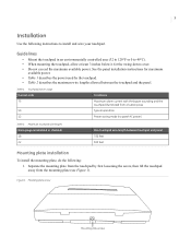
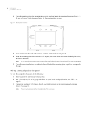
... touchpad away from a button press Typical operation Power saving mode (no panel AC power) Table 2. Figure 1. 3 Installation Use the following : 1. See the panel installation instructions for the swing-down cover. • Do not exceed the maximum available power. Mounting plate screw Mounting plate screw Maximum touchpad wire lengths Wire gauge (unshielded or shielded) 18 22 Max touchpad wire length between the touchpad and the panel. Table 1. Guidelines • Mount the touchpad in an environmentally controlled...
... touchpad away from a button press Typical operation Power saving mode (no panel AC power) Table 2. Figure 1. 3 Installation Use the following : 1. See the panel installation instructions for the swing-down cover. • Do not exceed the maximum available power. Mounting plate screw Mounting plate screw Maximum touchpad wire lengths Wire gauge (unshielded or shielded) 18 22 Max touchpad wire length between the touchpad and the panel. Table 1. Guidelines • Mount the touchpad in an environmentally controlled...
Installation Manual
Page 6
... of the connector. to 22-gauge wire from the panel to the touchpad location (see Figure 2). 4 FTP-1000 Installation Manual 2. Note: The wiring should extend from mounting properly. 5. For wall mounting, place the mounting plate on the wall and mark the mounting holes (see Table 2 on page 5). Connect the touchpad +12V, Bus A, Bus B, and GND terminals to the panel, do the following: 1. Figure 2. Remove panel AC and backup battery power. 2.
... of the connector. to 22-gauge wire from the panel to the touchpad location (see Figure 2). 4 FTP-1000 Installation Manual 2. Note: The wiring should extend from mounting properly. 5. For wall mounting, place the mounting plate on the wall and mark the mounting holes (see Table 2 on page 5). Connect the touchpad +12V, Bus A, Bus B, and GND terminals to the panel, do the following: 1. Figure 2. Remove panel AC and backup battery power. 2.
Installation Manual
Page 7
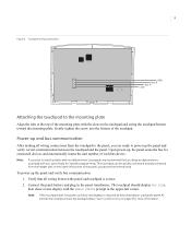
... backup battery. Verify that you keep an alphanumeric touchpad with the slots on page 9 for installer programming. See Troubleshooting on the touchpad and swing the touchpad bottom toward the mounting plate. The touchpad should display BUS SCAN, then show any display) or respond as described above the terminal strip. Touchpad wiring connections GND Bus B Bus A +12V Attaching the touchpad to power up and bus communication After making all wiring between the touchpad and the panel. 5 Figure 3. Power...
... backup battery. Verify that you keep an alphanumeric touchpad with the slots on page 9 for installer programming. See Troubleshooting on the touchpad and swing the touchpad bottom toward the mounting plate. The touchpad should display BUS SCAN, then show any display) or respond as described above the terminal strip. Touchpad wiring connections GND Bus B Bus A +12V Attaching the touchpad to power up and bus communication After making all wiring between the touchpad and the panel. 5 Figure 3. Power...
Installation Manual
Page 8
... the time display. After about three seconds, then release them . Test button function To test the button functions, do the following: Arm/disarm the system, activate the touchpad panics, bypass sensors, and turn chime on/off to verify correct operation. Refer to the panel's user manual for display function, button function, and system operation. Press and hold the 4, 5, and 6 buttons together for about 15 seconds of letters or numbers for...
... the time display. After about three seconds, then release them . Test button function To test the button functions, do the following: Arm/disarm the system, activate the touchpad panics, bypass sensors, and turn chime on/off to verify correct operation. Refer to the panel's user manual for display function, button function, and system operation. Press and hold the 4, 5, and 6 buttons together for about 15 seconds of letters or numbers for...
Installation Manual
Page 9
.... 3. Exit user programming by pressing 9 + system master code. The display shows SYSTEM MENU, then TIME - Press A or B until the display shows OPTIONS, then press #. Press A or B until the display shows BRIgHT 2 (default setting). 4. Enter a setting from 0 (LEDs off) to help compensate for Concord panels. The display shows the new setting. 5. Enter user programming mode by pressing: • * + 4 + # for Concord Express panels, • or * + 00 + # for lighting conditions at the touchpad location. 7 Adjusting display brightness You can adjust the background lighting (provided...
.... 3. Exit user programming by pressing 9 + system master code. The display shows SYSTEM MENU, then TIME - Press A or B until the display shows OPTIONS, then press #. Press A or B until the display shows BRIgHT 2 (default setting). 4. Enter a setting from 0 (LEDs off) to help compensate for Concord panels. The display shows the new setting. 5. Enter user programming mode by pressing: • * + 4 + # for Concord Express panels, • or * + 00 + # for lighting conditions at the touchpad location. 7 Adjusting display brightness You can adjust the background lighting (provided...
Installation Manual
Page 10
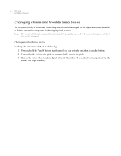
... any button activity at that specific touchpad. Note: Chime and trouble beep tones sound (using the default frequency) during, or within 15 seconds of no touchpad activity, the steady tone stops sounding. Change status tone pitch To change the status tone pitch, do the following: 1. 8 FTP-1000 Installation Manual Changing chime and trouble beep tones The frequency (pitch) of chime and trouble beep tones from each touchpad can be adjusted to a more desirable or distinct tone, and to lower the pitch...
... any button activity at that specific touchpad. Note: Chime and trouble beep tones sound (using the default frequency) during, or within 15 seconds of no touchpad activity, the steady tone stops sounding. Change status tone pitch To change the status tone pitch, do the following: 1. 8 FTP-1000 Installation Manual Changing chime and trouble beep tones The frequency (pitch) of chime and trouble beep tones from each touchpad can be adjusted to a more desirable or distinct tone, and to lower the pitch...
Installation Manual
Page 11
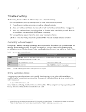
... controlled by a switch. Online publication library Another great resource for technical support. Table 3. Check for correct bus wiring connections (green and white wires) at the equipment before calling for assistance with your GE Security products is our online publication library, available to do if the touchpad does not operate correctly. • The touchpad doesn't power up (no display and no beeps when buttons are provided as PDFs...
... controlled by a switch. Online publication library Another great resource for technical support. Table 3. Check for correct bus wiring connections (green and white wires) at the equipment before calling for assistance with your GE Security products is our online publication library, available to do if the touchpad does not operate correctly. • The touchpad doesn't power up (no display and no beeps when buttons are provided as PDFs...
Installation Manual
Page 12
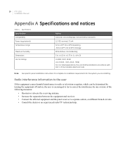
..., noncondensing 5 in . x 0.75 in accordance with Part 1 of the following measures: • Reorient or relocate the receiving antenna. • Increase the separation between the equipment and receiver. • Connect the affected equipment and the panel receiver to correct the interferance by one or more of the Canadian Electrical Code. 10 FTP-1000 Installation Manual Appendix A Specifications and notices Table 4. M89) For cUL listed...
..., noncondensing 5 in . x 0.75 in accordance with Part 1 of the following measures: • Reorient or relocate the receiving antenna. • Increase the separation between the equipment and receiver. • Connect the affected equipment and the panel receiver to correct the interferance by one or more of the Canadian Electrical Code. 10 FTP-1000 Installation Manual Appendix A Specifications and notices Table 4. M89) For cUL listed...


