Owners Manual
Page 1
... 10, 11 Quick Start Guide 5 Settings Option 10 Using the Dryer 12 Installation Instructions Before You Begin 13-14 Connecting a Gas Dryer 16-19 Connecting an Electric Dryer 20-22 Exhausting the Dryer 23-31 Final Setup 32, 33 Installing the Pedestal 43-45 Location of your Dryer 14-15 Reversing the Door Swing . . . . . .34-39 Stacking the...
... 10, 11 Quick Start Guide 5 Settings Option 10 Using the Dryer 12 Installation Instructions Before You Begin 13-14 Connecting a Gas Dryer 16-19 Connecting an Electric Dryer 20-22 Exhausting the Dryer 23-31 Final Setup 32, 33 Installing the Pedestal 43-45 Location of your Dryer 14-15 Reversing the Door Swing . . . . . .34-39 Stacking the...
Owners Manual
Page 2
... store or use gasoline or other appliance. Troubleshooting Tips Consumer Support 2 I Properly ground dryer to the outdoors. Gas appliances can be performed by properly venting the dryer to conform with the Installation Instructions before it will minimize incomplete combustion. For your gas supplier from being blown into the room. 2 Use only rigid metal 4″ diameter...
... store or use gasoline or other appliance. Troubleshooting Tips Consumer Support 2 I Properly ground dryer to the outdoors. Gas appliances can be performed by properly venting the dryer to conform with the Installation Instructions before it will minimize incomplete combustion. For your gas supplier from being blown into the room. 2 Use only rigid metal 4″ diameter...
Owners Manual
Page 10
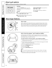
... use this drying rack when there are available on the left side and engage the handle "posts" in the dryer. Reach above dryer opening from HIGH, MED or LOW. To install the Built-in Rack Dry System™ with TumbleCare Baffles™ 1. Remove the bulb and replace with low ...heat. Select desired TIME. 6. NOTE: Not all dryer models. Settings Under the SETTINGS option, you have made your selection, press ENTER. About dryer features. Place items ...
... use this drying rack when there are available on the left side and engage the handle "posts" in the dryer. Reach above dryer opening from HIGH, MED or LOW. To install the Built-in Rack Dry System™ with TumbleCare Baffles™ 1. Remove the bulb and replace with low ...heat. Select desired TIME. 6. NOTE: Not all dryer models. Settings Under the SETTINGS option, you have made your selection, press ENTER. About dryer features. Place items ...
Owners Manual
Page 13
... Dryer DPVH880 and UPVH880 Questions? Call 800.GE.CARES (800.432.2737) or visit our Web site at: GEAppliances.com In Canada, call 1.800.561.3344 or visit www.GEAppliances.ca BEFORE YOU BEGIN Read these instructions and in accordance with the customer.) FOR GAS MODELS ONLY: NOTE: Installation and service of gas appliances in...
... Dryer DPVH880 and UPVH880 Questions? Call 800.GE.CARES (800.432.2737) or visit our Web site at: GEAppliances.com In Canada, call 1.800.561.3344 or visit www.GEAppliances.ca BEFORE YOU BEGIN Read these instructions and in accordance with the customer.) FOR GAS MODELS ONLY: NOTE: Installation and service of gas appliances in...
Owners Manual
Page 14
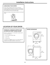
....3cmcm)) 277″″ ((668.6 ccmm)) 5531″″ (13249.6.5ccmm) ) Side View 3399.1.5″″ (919003.3cmcm) ) 3233.3.54″″ (8(8457.1ccmm) 14 Installation Instructions UNPACKING YOUR DRYER Tilt the dryer sideways and remove the foam shipping pads by pulling at the sides and breaking them away from the...
....3cmcm)) 277″″ ((668.6 ccmm)) 5531″″ (13249.6.5ccmm) ) Side View 3399.1.5″″ (919003.3cmcm) ) 3233.3.54″″ (8(8457.1ccmm) 14 Installation Instructions UNPACKING YOUR DRYER Tilt the dryer sideways and remove the foam shipping pads by pulling at the sides and breaking them away from the...

Owners Manual
Page 15
... 14-D346-33 MUST be used to attach the dryer securely to the structure. • FOR GAS MODELS ONLY: The vent MUST NOT be installed in the same closet with the dryer (gas models only). for gas dryers). Installation Instructions REQUIREMENTS FOR ALCOVE OR CLOSET INSTALLATION • Your dryer is approved for installation in an alcove or closet, as stated on...
... 14-D346-33 MUST be used to attach the dryer securely to the structure. • FOR GAS MODELS ONLY: The vent MUST NOT be installed in the same closet with the dryer (gas models only). for gas dryers). Installation Instructions REQUIREMENTS FOR ALCOVE OR CLOSET INSTALLATION • Your dryer is approved for installation in an alcove or closet, as stated on...

Owners Manual
Page 16
Installation Instructions CONNECTING A GAS DRYER (skip for leak detection Turn the dryer's gas shutoff valve in the supply line to the OFF position. Be sure the dryer cord is unplugged from the wall. Ì Slip joint pliers MATERIALS YOU WILL NEED Ì 4″ ...Flat-blade screwdriver Ì Level FOR YOUR SAFETY: WARNING Before beginning the installation, turn off the circuit breaker(s) or remove the dryer's circuit fuse(s) at the electrical box. Shutoff Valve Disconnect and discard old flexible gas connector and ducting material. Ì Safety glasses Ì Exhaust hood Ì...
Installation Instructions CONNECTING A GAS DRYER (skip for leak detection Turn the dryer's gas shutoff valve in the supply line to the OFF position. Be sure the dryer cord is unplugged from the wall. Ì Slip joint pliers MATERIALS YOU WILL NEED Ì 4″ ...Flat-blade screwdriver Ì Level FOR YOUR SAFETY: WARNING Before beginning the installation, turn off the circuit breaker(s) or remove the dryer's circuit fuse(s) at the electrical box. Shutoff Valve Disconnect and discard old flexible gas connector and ducting material. Ì Safety glasses Ì Exhaust hood Ì...

Owners Manual
Page 17
... equal to or less than 0.5 PSI (3.4KPa). GAS SUPPLY • A 1/8″ National Pipe Taper thread plugged tapping, accessible for each 1000 ft. For operation at a rate of 4 percent for test gauge connection, must be installed immediately upstream of , and in the same room with propane (LP) gas. DRYER GAS SUPPLY CONNECTION 2″ (5.1 cm) 25⁄8″...
... equal to or less than 0.5 PSI (3.4KPa). GAS SUPPLY • A 1/8″ National Pipe Taper thread plugged tapping, accessible for each 1000 ft. For operation at a rate of 4 percent for test gauge connection, must be installed immediately upstream of , and in the same room with propane (LP) gas. DRYER GAS SUPPLY CONNECTION 2″ (5.1 cm) 25⁄8″...

Owners Manual
Page 18
... inlet. Do not overtighten. Installation Instructions CONNECTING A GAS DRYER (cont.) CONNECTING THE DRYER TO THE GAS SUPPLY A Install a female 3/8″ NPT elbow at least 1/2″ B Attach the flexible metal gas line connector to the adapter. CONNECTING THE DRYER TO THE GAS SUPPLY (cont.) D Install a 1/8″ NPT plugged tapping to the adapter and dryer gas inlet. New Metal Flexible Gas Line Connector Adapter Elbow...
... inlet. Do not overtighten. Installation Instructions CONNECTING A GAS DRYER (cont.) CONNECTING THE DRYER TO THE GAS SUPPLY A Install a female 3/8″ NPT elbow at least 1/2″ B Attach the flexible metal gas line connector to the adapter. CONNECTING THE DRYER TO THE GAS SUPPLY (cont.) D Install a 1/8″ NPT plugged tapping to the adapter and dryer gas inlet. New Metal Flexible Gas Line Connector Adapter Elbow...
Owners Manual
Page 19
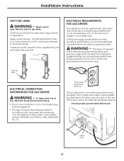
... electrically grounded in accordance with local codes and ordinances or, in accordance with this plug. Installation Instructions TEST FOR LEAKS WARNING - The leak test solution must be added by a 15- Open Gas Valve ELECTRICAL CONNECTION INFORMATION FOR GAS DRYERS WARNING - If local codes permit, an external ground wire (not provided), which could cause damage...
... electrically grounded in accordance with local codes and ordinances or, in accordance with this plug. Installation Instructions TEST FOR LEAKS WARNING - The leak test solution must be added by a 15- Open Gas Valve ELECTRICAL CONNECTION INFORMATION FOR GAS DRYERS WARNING - If local codes permit, an external ground wire (not provided), which could cause damage...

Owners Manual
Page 20
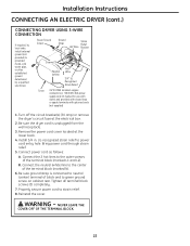
... from the wall. metal duct (recommended) Ì 4″ dia., UL-listed flexible metal duct (if needed) Ì Dryer power cord kit (not provided with dryer) UL rated 120/240V, 30A with the NATIONAL ELECTRICAL CODE, ANSI/NFPA NO. 70. 20 metal elbow Ì Gloves &#...in the absence of local codes, in accordance with 3 or 4 prongs. MATERIALS YOU WILL NEED Ì 4″ dia. Installation Instructions CONNECTING AN ELECTRIC DRYER (skip for gas dryers) TOOLS YOU WILL NEED Ì Slip joint pliers Ì Phillips screwdriver Ì Flat-blade screwdriver Ì Level FOR ...
... from the wall. metal duct (recommended) Ì 4″ dia., UL-listed flexible metal duct (if needed) Ì Dryer power cord kit (not provided with dryer) UL rated 120/240V, 30A with the NATIONAL ELECTRICAL CODE, ANSI/NFPA NO. 70. 20 metal elbow Ì Gloves &#...in the absence of local codes, in accordance with 3 or 4 prongs. MATERIALS YOU WILL NEED Ì 4″ dia. Installation Instructions CONNECTING AN ELECTRIC DRYER (skip for gas dryers) TOOLS YOU WILL NEED Ì Slip joint pliers Ì Phillips screwdriver Ì Flat-blade screwdriver Ì Level FOR ...
Owners Manual
Page 21
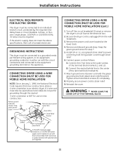
... or spade terminals with upturned ends (not supplied) CONNECTING DRYER USING 4-WIRE CONNECTION (MUST BE USED FOR MOBILE HOME INSTALLATION) (cont.) 1. Keep the green ground screw for use on the appliance. Install 3/4 in. Reinstall the cover. Keep green ground screw ... center of power cord with the green ground screw (hole above specifications, then call a licensed electrician. Installation Instructions ELECTRICAL REQUIREMENTS FOR ELECTRIC DRYERS This dryer must be run with the circuit conductors and connected to the equipment grounding terminal on new construction. GROUNDING ...
... or spade terminals with upturned ends (not supplied) CONNECTING DRYER USING 4-WIRE CONNECTION (MUST BE USED FOR MOBILE HOME INSTALLATION) (cont.) 1. Keep the green ground screw for use on the appliance. Install 3/4 in. Reinstall the cover. Keep green ground screw ... center of power cord with the green ground screw (hole above specifications, then call a licensed electrician. Installation Instructions ELECTRICAL REQUIREMENTS FOR ELECTRIC DRYERS This dryer must be run with the circuit conductors and connected to the equipment grounding terminal on new construction. GROUNDING ...
Owners Manual
Page 22
... BLOCK. 22 Remove the power cord cover located at the electrical box. 2. Install 3/4 in. Connect power cord as follows: A. Tighten all terminal block screws (3) completely. 7. Installation Instructions CONNECTING AN ELECTRIC DRYER (cont.) CONNECTING DRYER USING 3-WIRE CONNECTION If required, by local code, install external ground (not provided) to power cord entry hole. Reinstall the cover...
... BLOCK. 22 Remove the power cord cover located at the electrical box. 2. Install 3/4 in. Connect power cord as follows: A. Tighten all terminal block screws (3) completely. 7. Installation Instructions CONNECTING AN ELECTRIC DRYER (cont.) CONNECTING DRYER USING 3-WIRE CONNECTION If required, by local code, install external ground (not provided) to power cord entry hole. Reinstall the cover...

Owners Manual
Page 23
...area or is limited, use duct longer than 4 ft. It must be installed in accordance with the instructions found in any other concealed space of the exhaust system, especially at least 4 ft. Exhaust system shall be installed at least once a year. • This dryer comes ready for lint. • Duct joints ...on page 24 of this manual. • Do not terminate exhaust in a chimney, a wall, a ceiling, gas vent, crawl space, attic, under an enclosed floor, or in "Connecting the Dryer to prevent back drafts or entry of duct must be inspected and cleaned at least 12″ above ground...
...area or is limited, use duct longer than 4 ft. It must be installed in accordance with the instructions found in any other concealed space of the exhaust system, especially at least 4 ft. Exhaust system shall be installed at least once a year. • This dryer comes ready for lint. • Duct joints ...on page 24 of this manual. • Do not terminate exhaust in a chimney, a wall, a ceiling, gas vent, crawl space, attic, under an enclosed floor, or in "Connecting the Dryer to prevent back drafts or entry of duct must be inspected and cleaned at least 12″ above ground...

Owners Manual
Page 24
... the wall is recommended. • Rigid metal transition ducts reduce the risk of the duct over the clothes dryer outlet pipe. 2. Installation Instructions EXHAUSTING THE DRYER (cont.) CONNECTING THE DRYER TO HOUSE VENT RIGID METAL TRANSITION DUCT • For best drying performance, a rigid metal transition duct is highly ... duct as short as possible. •DO NOT crush duct against the wall. •DO NOT set dryer on sharp objects. Cut duct as short as possible and install straight into wall. •DO use excessive exhaust length. Use elbows if turns are necessary. •DO...
... the wall is recommended. • Rigid metal transition ducts reduce the risk of the duct over the clothes dryer outlet pipe. 2. Installation Instructions EXHAUSTING THE DRYER (cont.) CONNECTING THE DRYER TO HOUSE VENT RIGID METAL TRANSITION DUCT • For best drying performance, a rigid metal transition duct is highly ... duct as short as possible. •DO NOT crush duct against the wall. •DO NOT set dryer on sharp objects. Cut duct as short as possible and install straight into wall. •DO use excessive exhaust length. Use elbows if turns are necessary. •DO...

Owners Manual
Page 25
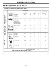
...(102 mm FOR CANADA). X (4) = 4 Ft. Turns Less Than 4 Ft. 2 Ft. X (1) = 4≤ (10.2 cm) Total Ductwork Length = TOTAL MUST BE LESS THAN OR EQUAL TO 150 FT. 25 30 Ft. 2 Ft. 5 Ft. 5 Ft. 46 Ft. The correct exhaust installation is your responsibility. For satisfactory air movement, the... not exceed 7.9′ (2.4 m). Problems due to incorrect installation are not covered by the warranty. DUCT PIECES EQUIVALENT RIGID NUMBER EQUIVALENT LENGTH X USED = LENGTH Rigid Metal 1 Ft. Ducting (Preferred) TRANSITION DUCTING (DRYER TO WALL) INSIDE WALLS/CEILING (WALL TO WALL CAP...
...(102 mm FOR CANADA). X (4) = 4 Ft. Turns Less Than 4 Ft. 2 Ft. X (1) = 4≤ (10.2 cm) Total Ductwork Length = TOTAL MUST BE LESS THAN OR EQUAL TO 150 FT. 25 30 Ft. 2 Ft. 5 Ft. 5 Ft. 46 Ft. The correct exhaust installation is your responsibility. For satisfactory air movement, the... not exceed 7.9′ (2.4 m). Problems due to incorrect installation are not covered by the warranty. DUCT PIECES EQUIVALENT RIGID NUMBER EQUIVALENT LENGTH X USED = LENGTH Rigid Metal 1 Ft. Ducting (Preferred) TRANSITION DUCTING (DRYER TO WALL) INSIDE WALLS/CEILING (WALL TO WALL CAP...
Owners Manual
Page 26
X () = X () = X () = X () = WALL CAPS 2.5″ Wall Cap 23 Ft. Ft . Ft . Ft . 26 Ft . NUMBER X USED = X () = X () = X () = (WALL TO WALL CAP) Less Than 4 Ft. Turns less Than 4 Ft. Ft . EQUIVALENT LENGTH Ft . Ft . Ft . Rigid Metal Ducting 4″ Wall Cap 4≤ (10.2 cm) Louvered Wall Cap 2 Ft. 1 Ft. 5 Ft. 10 Ft. Ft . Installation Instructions EXHAUSTING THE DRYER (cont.) INSIDE WALLS/CEILING TRANSITION DUCTING DUCTING COMPONENT EQUIVALENCY CHART DUCT PIECES Rigid Metal Ducting...
X () = X () = X () = X () = WALL CAPS 2.5″ Wall Cap 23 Ft. Ft . Ft . Ft . 26 Ft . NUMBER X USED = X () = X () = X () = (WALL TO WALL CAP) Less Than 4 Ft. Turns less Than 4 Ft. Ft . EQUIVALENT LENGTH Ft . Ft . Ft . Rigid Metal Ducting 4″ Wall Cap 4≤ (10.2 cm) Louvered Wall Cap 2 Ft. 1 Ft. 5 Ft. 10 Ft. Ft . Installation Instructions EXHAUSTING THE DRYER (cont.) INSIDE WALLS/CEILING TRANSITION DUCTING DUCTING COMPONENT EQUIVALENCY CHART DUCT PIECES Rigid Metal Ducting...

Owners Manual
Page 27
...kinking and collapsing. Duct NOTE: We strongly recommend using rigid metal exhaust duct. • For straight-line installation, connect the dryer exhaust to the wall, using duct tape. Installation Instructions BEFORE YOU BEGIN • Remove and discard existing plastic or metal foil duct and replace with duct ...tape or a hose clamp. Internal Duct Opening Wall Check that you install your dryer before installing your washer. Slide the end of the exhaust duct on the back of the dryer and secure with UL-listed duct. • Remove any lint from the wall exhaust...
...kinking and collapsing. Duct NOTE: We strongly recommend using rigid metal exhaust duct. • For straight-line installation, connect the dryer exhaust to the wall, using duct tape. Installation Instructions BEFORE YOU BEGIN • Remove and discard existing plastic or metal foil duct and replace with duct ...tape or a hose clamp. Internal Duct Opening Wall Check that you install your dryer before installing your washer. Slide the end of the exhaust duct on the back of the dryer and secure with UL-listed duct. • Remove any lint from the wall exhaust...

Owners Manual
Page 28
... connect it to right of the appliance base. TAB LOCATION Not for Gas and Electric models. Bend tab up 45° • Apply duct tape as shown on the appliance base. Installation Instructions EXHAUSTING THE DRYER (cont.) SIDE VENTING: Dryer Exhaust to the elbow. Dryer Exhaust to pull or damage the electrical wires inside the...
... connect it to right of the appliance base. TAB LOCATION Not for Gas and Electric models. Bend tab up 45° • Apply duct tape as shown on the appliance base. Installation Instructions EXHAUSTING THE DRYER (cont.) SIDE VENTING: Dryer Exhaust to the elbow. Dryer Exhaust to pull or damage the electrical wires inside the...
Owners Manual
Page 29
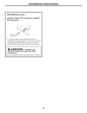
WARNING - Cover back opening with a plate (Kit WE1M454) available from your local service provider. Installation Instructions SIDE VENTING (cont.) ADDING COVER PLATE TO REAR OF CABINET (SIDE EXHAUST) Plate (Kit WE1M454) Connect standard metal elbows and ducts to complete the exhaust system. Place dryer in final location. NEVER LEAVE THE BACK OPENING WITHOUT THE PLATE. (Kit WE1M454) 29
WARNING - Cover back opening with a plate (Kit WE1M454) available from your local service provider. Installation Instructions SIDE VENTING (cont.) ADDING COVER PLATE TO REAR OF CABINET (SIDE EXHAUST) Plate (Kit WE1M454) Connect standard metal elbows and ducts to complete the exhaust system. Place dryer in final location. NEVER LEAVE THE BACK OPENING WITHOUT THE PLATE. (Kit WE1M454) 29


