Installation Instructions
Page 1
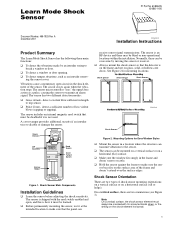
... two different detection modes: ❑ Gross Attack - See Figure 2 for Door/Window Styles ❑ Mount the sensor in a location where the structure can receive sensor signal transmissions. /HDUQ 0RGH 6KRFN 6HQVRU ITI Part No. 60-886-95 60-886-11-95 Document Number: 466-1925 Rev. ing the sensor cover. detect a sufficient number of shock sensor mounting orientations; A cover tamper provides additional security if an intruder tries to make sure that the panel can transmit...
... two different detection modes: ❑ Gross Attack - See Figure 2 for Door/Window Styles ❑ Mount the sensor in a location where the structure can receive sensor signal transmissions. /HDUQ 0RGH 6KRFN 6HQVRU ITI Part No. 60-886-95 60-886-11-95 Document Number: 466-1925 Rev. ing the sensor cover. detect a sufficient number of shock sensor mounting orientations; A cover tamper provides additional security if an intruder tries to make sure that the panel can transmit...
Installation Instructions
Page 2
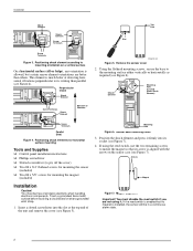
... . Arrows Magnet Figure 7. Installation Shock Element ON 1 2 3 4 5 6 LOGO Shock Element Screw Terminals LOGO Screw Terminals ON 1 2 3 4 5 6 Figure 3. Perpendicular (Good) ON 1 2 3 4 5 6 LOGO Shock Element Screw Terminals Shock Element Direction of all static electricity when handling electronic components. Using the flathead mounting screws, secure the base to mount the magnet so that its writing than others. You must disable the reed switch if you are better...
... . Arrows Magnet Figure 7. Installation Shock Element ON 1 2 3 4 5 6 LOGO Shock Element Screw Terminals LOGO Screw Terminals ON 1 2 3 4 5 6 Figure 3. Perpendicular (Good) ON 1 2 3 4 5 6 LOGO Shock Element Screw Terminals Shock Element Direction of all static electricity when handling electronic components. Using the flathead mounting screws, secure the base to mount the magnet so that its writing than others. You must disable the reed switch if you are better...
Installation Instructions
Page 3
... panel memory. Reed Switch Setting After adjusting the sensor sensitivity, set DIP switches 1 and 2 to light for complete programming details. RF Testing This section describes the basic steps for appropriate response from system sirens. 4. Listen for testing the sensor. Replace only with the reed switch if DIP switch 5 is reached within the most recent 30 seconds, the alarm will trip and the LED will blink for Gross Attack, set DIP switch 5 to Program mode. 2. Observe polarity when installing a new battery...
... panel memory. Reed Switch Setting After adjusting the sensor sensitivity, set DIP switches 1 and 2 to light for complete programming details. RF Testing This section describes the basic steps for appropriate response from system sirens. 4. Listen for testing the sensor. Replace only with the reed switch if DIP switch 5 is reached within the most recent 30 seconds, the alarm will trip and the LED will blink for Gross Attack, set DIP switch 5 to Program mode. 2. Observe polarity when installing a new battery...
Installation Instructions
Page 4
.... Specifications Specifications Compatibility All ITI 319.5 MHz Learn Mode Panels/Receivers Case dimensions 1.4 inches (3.5 cm) W x 6.0 inches (15.2 cm) L x 1.25 inches (3.2 cm) H Operating temperature .. 32° to 122° F (0° to 50° C) Storage temperature ...... -29° to 140° F (-34° to 60° C) Humidity 90% relative humidity non-condensing Battery Duracell DL123A or Sanyo CR123A 3V Lithium (ITI part number 34-030) Transmitter...
.... Specifications Specifications Compatibility All ITI 319.5 MHz Learn Mode Panels/Receivers Case dimensions 1.4 inches (3.5 cm) W x 6.0 inches (15.2 cm) L x 1.25 inches (3.2 cm) H Operating temperature .. 32° to 122° F (0° to 50° C) Storage temperature ...... -29° to 140° F (-34° to 60° C) Humidity 90% relative humidity non-condensing Battery Duracell DL123A or Sanyo CR123A 3V Lithium (ITI part number 34-030) Transmitter...


