Installation Instructions
Page 1
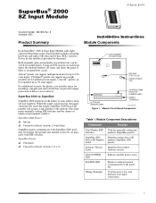
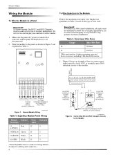
...power, bus, and hardwire zone input connections. 1 SuperBus 2000 Panels R Advent R Concord (software versions 2.0 and later) SuperBus panels communicate with DIP switches. Module Circuit Board Components Table 1. Module Component Descriptions Component Function Unit Number DIP Used for the module is an open and normally closed detectors can support up to auto-address module unit numbers. Power for manually setting unit Switches numbers (SuperBus panels). SuperBus 2000 vs. Using an EOL resistor on each loop input, the module monitors all zones and alerts the panel...
...power, bus, and hardwire zone input connections. 1 SuperBus 2000 Panels R Advent R Concord (software versions 2.0 and later) SuperBus panels communicate with DIP switches. Module Circuit Board Components Table 1. Module Component Descriptions Component Function Unit Number DIP Used for the module is an open and normally closed detectors can support up to auto-address module unit numbers. Power for manually setting unit Switches numbers (SuperBus panels). SuperBus 2000 vs. Using an EOL resistor on each loop input, the module monitors all zones and alerts the panel...
Installation Instructions
Page 2
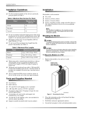
... cabinet Installation Instructions for bus devices and hardwired sensors that require it aside (Figure 2). R When using self or remotely powered devices with included screws. 2 R Terminate each SuperBus 2000 8Z Input Module is 35 mA. For normally closed circuits, wire the resistor in the UltraGard cabinet. R Inside a Concord cabinet. Refer to a wall. Installation Guidelines Installation Guidelines R For the maximum number of all static electricity when handling electronic components. R Always install the...
... cabinet Installation Instructions for bus devices and hardwired sensors that require it aside (Figure 2). R When using self or remotely powered devices with included screws. 2 R Terminate each SuperBus 2000 8Z Input Module is 35 mA. For normally closed circuits, wire the resistor in the UltraGard cabinet. R Inside a Concord cabinet. Refer to a wall. Installation Guidelines Installation Guidelines R For the maximum number of all static electricity when handling electronic components. R Always install the...
Installation Instructions
Page 3
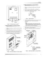
... location (Figure 4). 4. MOUNTING HOLES Installation To Mount the Module in Figure 6). 6. Mounting the Module in Figure 5 (supplied with Concord panel accessory package) Figure 6. USABLE MOUNTING CLIPS (6) PANEL CABINET (COVER NOT SHOWN) MOUNTED MODULE SIDE TAB MOUNT WITH SELF TAPPING SCREWS MOUNTED MODULE 9712G11A.DSF ROOM FOR 3RD MODULE Figure 4. Remove AC panel power and disconnect the backup battery. 2. Remove the module cover and set it aside (Figure 2). 3. PANEL END MODULE END 8573g64A.DSF...
... location (Figure 4). 4. MOUNTING HOLES Installation To Mount the Module in Figure 6). 6. Mounting the Module in Figure 5 (supplied with Concord panel accessory package) Figure 6. USABLE MOUNTING CLIPS (6) PANEL CABINET (COVER NOT SHOWN) MOUNTED MODULE SIDE TAB MOUNT WITH SELF TAPPING SCREWS MOUNTED MODULE 9712G11A.DSF ROOM FOR 3RD MODULE Figure 4. Remove AC panel power and disconnect the backup battery. 2. Remove the module cover and set it aside (Figure 2). 3. PANEL END MODULE END 8573g64A.DSF...
Installation Instructions
Page 4
... NORMALLY OPEN (N/O) CONTACTS IN PARALLEL 2.0K OHM EOL RESISTOR 49-467 (INSTALL AT LAST DEVICE) 9712G04A.DSF Figure 8. General Module Wiring Table 4. Zone Input Wire Runs Gauge Max. SuperBus Module/Panel Wiring Module Advent* Terminals UltraGard 13 Red 12 (+12VDC) 14 (BUS A) Green 13 15 (BUS B) White 14 16 (GND) Black 15 Concord 4 5 6 3 * Panel SuperBus device connector wiring harness. (Connect to either fire or burglary applications. Wiring the Module Wiring the Module To Wire the Module to a Panel To Wire Detectors...
... NORMALLY OPEN (N/O) CONTACTS IN PARALLEL 2.0K OHM EOL RESISTOR 49-467 (INSTALL AT LAST DEVICE) 9712G04A.DSF Figure 8. General Module Wiring Table 4. Zone Input Wire Runs Gauge Max. SuperBus Module/Panel Wiring Module Advent* Terminals UltraGard 13 Red 12 (+12VDC) 14 (BUS A) Green 13 15 (BUS B) White 14 16 (GND) Black 15 Concord 4 5 6 3 * Panel SuperBus device connector wiring harness. (Connect to either fire or burglary applications. Wiring the Module Wiring the Module To Wire the Module to a Panel To Wire Detectors...
Installation Instructions
Page 5
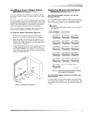
...-plate (see Figure 3 for automatic). Connect the normally closed reed switch (in series with a 2.0K ohm EOL resistor) to the module ZONE 1 (1) and ZONE COMMON (2) terminals as shown in Figure 8. Installing a Cover Tamper Switch Installing a Cover Tamper Switch Setting the Module Unit Numbers If you are located at the reed switch inside a cabinet, you need to add cover tamper detection. Once programmed, if someone opens the module cover, the tamper switch opens and causes an alarm.
...-plate (see Figure 3 for automatic). Connect the normally closed reed switch (in series with a 2.0K ohm EOL resistor) to the module ZONE 1 (1) and ZONE COMMON (2) terminals as shown in Figure 8. Installing a Cover Tamper Switch Installing a Cover Tamper Switch Setting the Module Unit Numbers If you are located at the reed switch inside a cabinet, you need to add cover tamper detection. Once programmed, if someone opens the module cover, the tamper switch opens and causes an alarm.
Installation Instructions
Page 6
... panel AC power. Alphanumeric touchpad displays should come on . 3. Verify that all wiring between the panel and module is correct. 2. Alphanumeric touchpad displays should flash to indicate successful communication with the panel. œÌi If the green POWER LED is not on or the red BUS LED does not flash, remove AC panel power, disconnect the backup battery(s), and see Table 6 "Troubleshooting." Existing Installations Concord Panels- Enter Item Number 48001 to PROGRAM. Turn on or the red BUS LED does not flash, set the RUN/PROGRAM switch...
... panel AC power. Alphanumeric touchpad displays should come on . 3. Verify that all wiring between the panel and module is correct. 2. Alphanumeric touchpad displays should flash to indicate successful communication with the panel. œÌi If the green POWER LED is not on or the red BUS LED does not flash, remove AC panel power, disconnect the backup battery(s), and see Table 6 "Troubleshooting." Existing Installations Concord Panels- Enter Item Number 48001 to PROGRAM. Turn on or the red BUS LED does not flash, set the RUN/PROGRAM switch...
Installation Instructions
Page 7
... 6. Verify that module DIP switch 1 is set to "A." 4. Troubleshooting Problem The green POWER LED stays off , replace the module. 1. The red BUS LED doesn't flash to indicate communication with the same unit number setting. 2. Check for incorrect wiring connections. 3. Remove zones and try installing the module without the zones. 6. Compatibility: Advent, Concord, UltraGard Power Requirements: 12 VDC nominal, 35 mA maximum (from panel) Panel Data Bus: ITI SuperBus and SuperBus 2000 digital data bus Inputs: Eight supervised, hardwire zones Storage Temperature...
... 6. Verify that module DIP switch 1 is set to "A." 4. Troubleshooting Problem The green POWER LED stays off , replace the module. 1. The red BUS LED doesn't flash to indicate communication with the same unit number setting. 2. Check for incorrect wiring connections. 3. Remove zones and try installing the module without the zones. 6. Compatibility: Advent, Concord, UltraGard Power Requirements: 12 VDC nominal, 35 mA maximum (from panel) Panel Data Bus: ITI SuperBus and SuperBus 2000 digital data bus Inputs: Eight supervised, hardwire zones Storage Temperature...
Installation Instructions
Page 8
... and receiver. Interlogix and Concord are registered trademarks of Interlogix, Inc. can radiate radio frequency energy and, if not installed and used in a residential installation. This equipment generates, uses, and can void the user's authority to radio communications. ITI, Advent, UltraGard, and SuperBus are trademarks of Interlogix, Inc. 8 However, there is likely to cause harmful interference in accordance with the instruction manual...
... and receiver. Interlogix and Concord are registered trademarks of Interlogix, Inc. can radiate radio frequency energy and, if not installed and used in a residential installation. This equipment generates, uses, and can void the user's authority to radio communications. ITI, Advent, UltraGard, and SuperBus are trademarks of Interlogix, Inc. 8 However, there is likely to cause harmful interference in accordance with the instruction manual...


