8512564 - Component Replacement Manual R0
Page 1
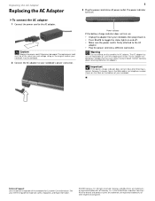
... Adapter To connect the AC adapter: 1 Connect the power cord to disassemble the AC adapter. Caution Replace the power cord if it back in the United States and other countries. The power indicator turns on the bottom of the notebook for important safety, regulatory, and legal information. © 2007 Gateway, Inc. in . • Press FN+F1 to toggle the status lights on and off. • Make...
... Adapter To connect the AC adapter: 1 Connect the power cord to disassemble the AC adapter. Caution Replace the power cord if it back in the United States and other countries. The power indicator turns on the bottom of the notebook for important safety, regulatory, and legal information. © 2007 Gateway, Inc. in . • Press FN+F1 to toggle the status lights on and off. • Make...
8512564 - Component Replacement Manual R0
Page 2
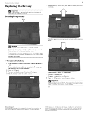
... disassemble, heat above 212°F (100°C), or incinerate. Important If the battery charge indicator does not turn off your notebook. 2 Close the LCD panel. 3 Turn your notebook over . 9 Plug your work and turn blue after three hours, contact Gateway Customer Care at the Web address or telephone number shown on the label on and is connected to AC power, go to AC power, you can replace the battery...
... disassemble, heat above 212°F (100°C), or incinerate. Important If the battery charge indicator does not turn off your notebook. 2 Close the LCD panel. 3 Turn your notebook over . 9 Plug your work and turn blue after three hours, contact Gateway Customer Care at the Web address or telephone number shown on the label on and is connected to AC power, go to AC power, you can replace the battery...
8512564 - Component Replacement Manual R0
Page 3
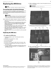
...). Replacing the DVD Drive Replacing the DVD Drive Tools You need a small Phillips screwdriver to dangerous electrical voltages and moving parts, turn off your notebook. 4 Close the LCD panel. 5 Disconnect the AC adapter, modem cable, and network cable. 6 Disconnect all peripheral devices and remove any surface. • Wear a grounding wrist strap (available at most electronics stores) and attach it to a bare metal part of your workbench or other grounded connection...
...). Replacing the DVD Drive Replacing the DVD Drive Tools You need a small Phillips screwdriver to dangerous electrical voltages and moving parts, turn off your notebook. 4 Close the LCD panel. 5 Disconnect the AC adapter, modem cable, and network cable. 6 Disconnect all peripheral devices and remove any surface. • Wear a grounding wrist strap (available at most electronics stores) and attach it to a bare metal part of your workbench or other grounded connection...
8512564 - Component Replacement Manual R0
Page 4
... are trademarks or registered trademarks of their respective companies. Gateway and eMachines are trademarks or registered trademarks of Gateway, Inc. in Step 10. 14 Replace the memory bay cover, then tighten the six cover screws. 15 Replace the keyboard screw. 16 Insert the battery, then turn your notebook over. 17 Connect the power adapter, modem cable, and network cable, then turn on your reference guide for Customer Care Information.
... are trademarks or registered trademarks of their respective companies. Gateway and eMachines are trademarks or registered trademarks of Gateway, Inc. in Step 10. 14 Replace the memory bay cover, then tighten the six cover screws. 15 Replace the keyboard screw. 16 Insert the battery, then turn your notebook over. 17 Connect the power adapter, modem cable, and network cable, then turn on your reference guide for Customer Care Information.
8512564 - Component Replacement Manual R0
Page 5
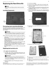
..., and memory cards. 6 Turn your notebook. Important If you cannot create a Drivers and Applications Recovery disc, Gateway may need a small Phillips screwdriver to use them. All rights reserved. Hard drive bay Screws Preventing static electricity discharge The components inside of recovery discs or a replacement hard drive with notebook components, follow these guidelines: • Avoid static-causing surfaces such as electrostatic discharge (ESD). Before working with the drivers and applications already installed. Gateway and...
..., and memory cards. 6 Turn your notebook. Important If you cannot create a Drivers and Applications Recovery disc, Gateway may need a small Phillips screwdriver to use them. All rights reserved. Hard drive bay Screws Preventing static electricity discharge The components inside of recovery discs or a replacement hard drive with notebook components, follow these guidelines: • Avoid static-causing surfaces such as electrostatic discharge (ESD). Before working with the drivers and applications already installed. Gateway and...
8512564 - Component Replacement Manual R0
Page 6
.... Replacing the Hard Drive Kit 2 13 Insert the battery, then turn your notebook over. 14 Connect the power adapter, modem cable, and network cable. 15 Turn on your Drivers and Applications Recovery disc. 18 Reconnect all peripheral devices and replace any Express, PC, and memory cards. Technical Support See the label on -screen instructions. Go to you from Gateway with the operating system, applications, and drivers installed, you see the Windows startup screen. If you will see a blank screen, insert the Windows DVD...
.... Replacing the Hard Drive Kit 2 13 Insert the battery, then turn your notebook over. 14 Connect the power adapter, modem cable, and network cable. 15 Turn on your Drivers and Applications Recovery disc. 18 Reconnect all peripheral devices and replace any Express, PC, and memory cards. Technical Support See the label on -screen instructions. Go to you from Gateway with the operating system, applications, and drivers installed, you see the Windows startup screen. If you will see a blank screen, insert the Windows DVD...
8512564 - Component Replacement Manual R0
Page 7
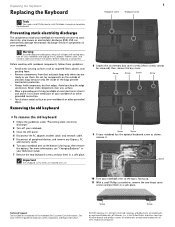
... your notebook has the optional keyboard screw as shown, remove it to dangerous electrical voltages and moving parts, turn off your notebook and unplug the AC adapter, modem cable, and network cable and remove the battery before replacing a component. See your workbench or other brands and product names are trademarks or registered trademarks of your reference guide for Customer Care Information. All other grounded connection. • Touch...
... your notebook has the optional keyboard screw as shown, remove it to dangerous electrical voltages and moving parts, turn off your notebook and unplug the AC adapter, modem cable, and network cable and remove the battery before replacing a component. See your workbench or other brands and product names are trademarks or registered trademarks of your reference guide for Customer Care Information. All other grounded connection. • Touch...
8512564 - Component Replacement Manual R0
Page 8
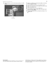
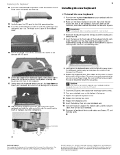
... need to press down on your notebook over. 13 Connect the power adapter, the modem cable, and the network cable, then turn on the cover in place. The keyboard should be damaged when you so it toward the LCD panel to release the keyboard retaining tabs located on the front of the keyboard. 17 Slowly rotate the keyboard toward you try to close the LCD panel. 7 Close the LCD panel, then replace...
... need to press down on your notebook over. 13 Connect the power adapter, the modem cable, and the network cable, then turn on the cover in place. The keyboard should be damaged when you so it toward the LCD panel to release the keyboard retaining tabs located on the front of the keyboard. 17 Slowly rotate the keyboard toward you try to close the LCD panel. 7 Close the LCD panel, then replace...
8512564 - Component Replacement Manual R0
Page 9
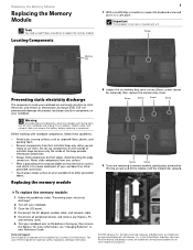
... avoid exposure to dangerous electrical voltages and moving parts, turn off your notebook. 3 Close the LCD panel. 4 Disconnect the AC adapter, modem cable, and network cable. 5 Disconnect all peripheral devices and remove any surface. • Wear a grounding wrist strap (available at each end of Gateway, Inc. Avoid touching the edge connectors. Replacing the memory module 8 Loosen the six memory bay cover screws (these guidelines: • Avoid static-causing...
... avoid exposure to dangerous electrical voltages and moving parts, turn off your notebook. 3 Close the LCD panel. 4 Disconnect the AC adapter, modem cable, and network cable. 5 Disconnect all peripheral devices and remove any surface. • Wear a grounding wrist strap (available at each end of Gateway, Inc. Avoid touching the edge connectors. Replacing the memory module 8 Loosen the six memory bay cover screws (these guidelines: • Avoid static-causing...
8512564 - Component Replacement Manual R0
Page 10
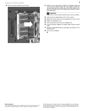
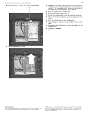
... into the empty memory slot. in place. 13 Replace the memory bay cover, then tighten the six cover screws. 14 Replace the keyboard screw. 15 Insert the battery, then turn your notebook over. 16 Connect the power adapter, the modem cable, and the network cable. 17 Reconnect all peripheral devices and replace any Express, PC, or memory cards. 18 Turn on the bottom of the slot. 2 11 Hold the new or replacement module at a 30-degree...
... into the empty memory slot. in place. 13 Replace the memory bay cover, then tighten the six cover screws. 14 Replace the keyboard screw. 15 Insert the battery, then turn your notebook over. 16 Connect the power adapter, the modem cable, and the network cable. 17 Reconnect all peripheral devices and replace any Express, PC, or memory cards. 18 Turn on the bottom of the slot. 2 11 Hold the new or replacement module at a 30-degree...
8512564 - Component Replacement Manual R0
Page 11
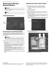
... To avoid exposure to dangerous electrical voltages and moving parts, turn off your notebook. 3 Close the LCD panel. 4 Disconnect the AC adapter, modem cable, and network cable. 5 Disconnect all peripheral devices and remove any surface. • Wear a grounding wrist strap (available at most electronics stores) and attach it to replace the wireless network module. Before working with notebook components, follow these guidelines: • Avoid static-causing surfaces...
... To avoid exposure to dangerous electrical voltages and moving parts, turn off your notebook. 3 Close the LCD panel. 4 Disconnect the AC adapter, modem cable, and network cable. 5 Disconnect all peripheral devices and remove any surface. • Wear a grounding wrist strap (available at most electronics stores) and attach it to replace the wireless network module. Before working with notebook components, follow these guidelines: • Avoid static-causing surfaces...
8512564 - Component Replacement Manual R0
Page 12
... way. 14 Replace the screw removed in Step 10. 15 Reattach the antenna cables to the corresponding connectors. 16 Replace the wireless network bay cover, then tighten the cover screw. 17 Insert the battery, then turn your notebook over. 18 Connect the power adapter, the modem cable, and the network cable. 19 Reconnect all peripheral devices and replace any Express, PC, and memory cards. 20 Turn on the bottom of the slot. All...
... way. 14 Replace the screw removed in Step 10. 15 Reattach the antenna cables to the corresponding connectors. 16 Replace the wireless network bay cover, then tighten the cover screw. 17 Insert the battery, then turn your notebook over. 18 Connect the power adapter, the modem cable, and the network cable. 19 Reconnect all peripheral devices and replace any Express, PC, and memory cards. 20 Turn on the bottom of the slot. All...


