8511725 - Gateway Service Guide
Page 3
Contents Replacing Notebook Components 1 Identifying the notebook model 2 Identifying components 3 Preparing your work space 4 Preventing static electricity discharge 5 Tape 5 Preparing the notebook 6 Removing the battery 6 Adding or replacing memory modules 7 Replacing the DVD ...
Contents Replacing Notebook Components 1 Identifying the notebook model 2 Identifying components 3 Preparing your work space 4 Preventing static electricity discharge 5 Tape 5 Preparing the notebook 6 Removing the battery 6 Adding or replacing memory modules 7 Replacing the DVD ...
8511725 - Gateway Service Guide
Page 5
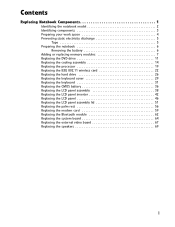
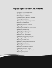
Replacing Notebook Components • Identifying the notebook model • Identifying components • Preparing your work space • Preventing static electricity discharge • Preparing the notebook • Adding or replacing memory modules • Replacing ...
Replacing Notebook Components • Identifying the notebook model • Identifying components • Preparing your work space • Preventing static electricity discharge • Preparing the notebook • Adding or replacing memory modules • Replacing ...
8511725 - Gateway Service Guide
Page 6
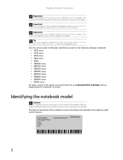
... be performed by an authorized field technician without jeopardizing the notebook's warranty. Online Support: Tech Support Phone: Hours: Model: S/No: support.gateway.com 2 Failure to anyone other than an authorized service provider. Replacing Notebook Components Important The photographs in this guide ...an e-mail with the subject "Service Guide Comments" to channel.services@gateway.com. Important This service guide is important that identifies the notebook model and its features. Identifying the notebook model Caution It is not intended to be provided to follow the approved tasks...
... be performed by an authorized field technician without jeopardizing the notebook's warranty. Online Support: Tech Support Phone: Hours: Model: S/No: support.gateway.com 2 Failure to anyone other than an authorized service provider. Replacing Notebook Components Important The photographs in this guide ...an e-mail with the subject "Service Guide Comments" to channel.services@gateway.com. Important This service guide is important that identifies the notebook model and its features. Identifying the notebook model Caution It is not intended to be provided to follow the approved tasks...
8511725 - Gateway Service Guide
Page 12
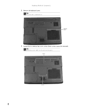
Screws Screws 8 Keyboard screw 3 Loosen the six memory bay cover screws (these screws cannot be captive. Tip The screw hole is marked with a K. Replacing Notebook Components 2 Remove the keyboard screw. Tip Depending on your model, not all screws may be removed).
Screws Screws 8 Keyboard screw 3 Loosen the six memory bay cover screws (these screws cannot be captive. Tip The screw hole is marked with a K. Replacing Notebook Components 2 Remove the keyboard screw. Tip Depending on your model, not all screws may be removed).
8511725 - Gateway Service Guide
Page 16
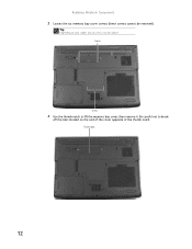
Tip Depending on the end of the cover opposite of the thumb notch. Replacing Notebook Components 3 Loosen the six memory bay cover screws (these screws cannot be captive. Screws Screws 4 Use the thumb notch to break off the tabs located on your model, not all screws may be removed). Thumb notch 12 Be careful not to lift the memory bay cover, then remove it.
Tip Depending on the end of the cover opposite of the thumb notch. Replacing Notebook Components 3 Loosen the six memory bay cover screws (these screws cannot be captive. Screws Screws 4 Use the thumb notch to break off the tabs located on your model, not all screws may be removed). Thumb notch 12 Be careful not to lift the memory bay cover, then remove it.
8511725 - Gateway Service Guide
Page 19
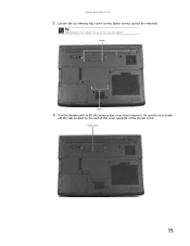
Screws Screws 4 Use the thumb notch to break off the tabs located on your model, not all screws may be removed). www.gateway.com 3 Loosen the six memory bay cover screws (these screws cannot be captive. Tip Depending on the end of the cover opposite of the thumb notch. Be careful not to lift the memory bay cover, then remove it. Thumb notch 15
Screws Screws 4 Use the thumb notch to break off the tabs located on your model, not all screws may be removed). www.gateway.com 3 Loosen the six memory bay cover screws (these screws cannot be captive. Tip Depending on the end of the cover opposite of the thumb notch. Be careful not to lift the memory bay cover, then remove it. Thumb notch 15
8511725 - Gateway Service Guide
Page 20
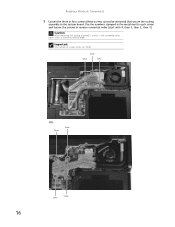
Replacing Notebook Components 5 Loosen the three or four screws (these screws cannot be removed) that secure the cooling assembly to each screw and loosen the screws in reverse numerical order (start with 4, then 3, then 2, then 1). Caution When loosening the cooling assembly's screws in the numbered holes, loosen them in the metal next to the system board. Screw Screw Screw -OR- Use the numbers stamped in reverse numerical order. Important The number of screws varies by model. Screw Screw Screw Screw 16
Replacing Notebook Components 5 Loosen the three or four screws (these screws cannot be removed) that secure the cooling assembly to each screw and loosen the screws in reverse numerical order (start with 4, then 3, then 2, then 1). Caution When loosening the cooling assembly's screws in the numbered holes, loosen them in the metal next to the system board. Screw Screw Screw -OR- Use the numbers stamped in reverse numerical order. Important The number of screws varies by model. Screw Screw Screw Screw 16
8511725 - Gateway Service Guide
Page 22
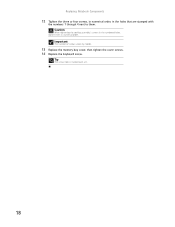
Caution When tightening the cooling assembly's screws in numerical order. Important The number of screws varies by model. 13 Replace the memory bay cover, then tighten the cover screws. 14 Replace the keyboard screw. Tip The screw hole is marked with the numbers 1 through 4 next to them in the numbered holes, tighten them . Replacing Notebook Components 12 Tighten the three or four screws, in numerical order, in the holes that are stamped with a K. 18
Caution When tightening the cooling assembly's screws in numerical order. Important The number of screws varies by model. 13 Replace the memory bay cover, then tighten the cover screws. 14 Replace the keyboard screw. Tip The screw hole is marked with the numbers 1 through 4 next to them in the numbered holes, tighten them . Replacing Notebook Components 12 Tighten the three or four screws, in numerical order, in the holes that are stamped with a K. 18
8511725 - Gateway Service Guide
Page 26
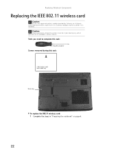
Tools you need to complete this task: Phillips #0 screwdriver Screws removed during this task: 1 black (wireless card) Select models only Wireless bay To replace the 802.11 wireless card: 1 Complete the steps in place during any and all operation of the notebook's wireless feature. ... cover be installed in this notebook. Replacing Notebook Components Replacing the IEEE 802.11 wireless card Caution By law, only approved wireless modules provided by Gateway, or a Gateway authorized representative, explicitly for this Gateway notebook may be in "Preparing the notebook" on page 6. 22
Tools you need to complete this task: Phillips #0 screwdriver Screws removed during this task: 1 black (wireless card) Select models only Wireless bay To replace the 802.11 wireless card: 1 Complete the steps in place during any and all operation of the notebook's wireless feature. ... cover be installed in this notebook. Replacing Notebook Components Replacing the IEEE 802.11 wireless card Caution By law, only approved wireless modules provided by Gateway, or a Gateway authorized representative, explicitly for this Gateway notebook may be in "Preparing the notebook" on page 6. 22
8511725 - Gateway Service Guide
Page 36
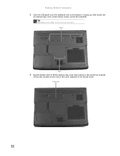
Tip Depending on the end of the cover opposite of the thumb notch. Screws Screws 6 Use the thumb notch to break off the tabs located on your model, not all screws may be removed). Be careful not to lift the memory bay cover, then remove it. Thumb notch 32 Replacing Notebook Components 5 Close the LCD panel, turn the notebook over so the bottom is facing up, then loosen the six memory bay cover screws (these screws cannot be captive.
Tip Depending on the end of the cover opposite of the thumb notch. Screws Screws 6 Use the thumb notch to break off the tabs located on your model, not all screws may be removed). Be careful not to lift the memory bay cover, then remove it. Thumb notch 32 Replacing Notebook Components 5 Close the LCD panel, turn the notebook over so the bottom is facing up, then loosen the six memory bay cover screws (these screws cannot be captive.
8511725 - Gateway Service Guide
Page 46
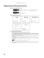
... complete this task: Scribe or non-marring tool 2 black (keyboard cover) 1-3 black (keyboard) 4 black (LCD panel hinges) 4 or 6 chrome (LCD panel assembly) 2 chrome (bracket) Select models only To replace the LCD panel inverter: 1 Complete the steps in "Preparing the notebook" on page 6. 2 If the notebook has IEEE 802.11 wireless networking...
... complete this task: Scribe or non-marring tool 2 black (keyboard cover) 1-3 black (keyboard) 4 black (LCD panel hinges) 4 or 6 chrome (LCD panel assembly) 2 chrome (bracket) Select models only To replace the LCD panel inverter: 1 Complete the steps in "Preparing the notebook" on page 6. 2 If the notebook has IEEE 802.11 wireless networking...
8511725 - Gateway Service Guide
Page 47
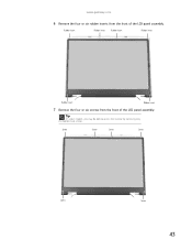
Tip On select models, you may be able to access the inverter by removing only the bottom two screws. www.gateway.com 6 Remove the four or six rubber inserts from the front of the LCD panel assembly. Screw Screw Screw Screw Screw Screw 43 Rubber insert Rubber insert Rubber insert Rubber insert Rubber insert Rubber insert 7 Remove the four or six screws from the front of the LCD panel assembly.
Tip On select models, you may be able to access the inverter by removing only the bottom two screws. www.gateway.com 6 Remove the four or six rubber inserts from the front of the LCD panel assembly. Screw Screw Screw Screw Screw Screw 43 Rubber insert Rubber insert Rubber insert Rubber insert Rubber insert Rubber insert 7 Remove the four or six screws from the front of the LCD panel assembly.
8511725 - Gateway Service Guide
Page 55
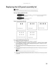
... 6. 2 If the notebook has IEEE 802.11 wireless networking built in, unplug the antenna cables from the notebook. 5 Remove the LCD panel by model. Scribe or non-marring tool Phillips #0 screwdriver Screws removed during this task: Flat-blade driver - OR - Tools you need to an existing LCD ... by following the instructions in "Replacing the keyboard" on page 38. 51 Tip You do not need to order a different lid. www.gateway.com Replacing the LCD panel assembly lid Caution LCD panel assembly lids vary by following the instructions in "Replacing the LCD panel assembly" on...
... 6. 2 If the notebook has IEEE 802.11 wireless networking built in, unplug the antenna cables from the notebook. 5 Remove the LCD panel by model. Scribe or non-marring tool Phillips #0 screwdriver Screws removed during this task: Flat-blade driver - OR - Tools you need to an existing LCD ... by following the instructions in "Replacing the keyboard" on page 38. 51 Tip You do not need to order a different lid. www.gateway.com Replacing the LCD panel assembly lid Caution LCD panel assembly lids vary by following the instructions in "Replacing the LCD panel assembly" on...
8511725 - Gateway Service Guide
Page 63
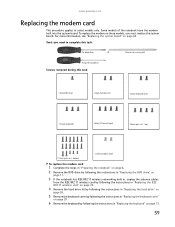
...must replace the system board. top) 17 black (palm rest - For more information, see "Replacing the system board" on these models, you need to select models only. Scribe or non-marring tool Phillips #0 screwdriver Screws removed during this task: Flat-blade driver - To replace the modem ... "Replacing the keyboard cover" on page 29. 6 Remove the keyboard by following the instructions in "Replacing the keyboard" on page 31. 59 www.gateway.com Replacing the modem card This procedure applies to complete this task: 1 black (DVD drive) 2 black (hard drive kit) 2 black (keyboard cover...
...must replace the system board. top) 17 black (palm rest - For more information, see "Replacing the system board" on these models, you need to select models only. Scribe or non-marring tool Phillips #0 screwdriver Screws removed during this task: Flat-blade driver - To replace the modem ... "Replacing the keyboard cover" on page 29. 6 Remove the keyboard by following the instructions in "Replacing the keyboard" on page 31. 59 www.gateway.com Replacing the modem card This procedure applies to complete this task: 1 black (DVD drive) 2 black (hard drive kit) 2 black (keyboard cover...

8511725 - Gateway Service Guide
Page 68
... 2 black (keyboard cover) 1-3 black (keyboard) 4 black (LCD panel hinges) 4 black (palm rest - top) 17 black (palm rest - OR - bottom) 2 chrome (modem) Select models only 4 black (system board) To replace the system board: 1 Complete the steps in "Preparing the notebook" on page 6. 2 Remove the memory from the old system ...
... 2 black (keyboard cover) 1-3 black (keyboard) 4 black (LCD panel hinges) 4 black (palm rest - top) 17 black (palm rest - OR - bottom) 2 chrome (modem) Select models only 4 black (system board) To replace the system board: 1 Complete the steps in "Preparing the notebook" on page 6. 2 Remove the memory from the old system ...
8512488 - Gateway Notebook Reference Guide R2
Page 3
Contents Chapter 1: About This Reference 1 About this guide 2 Accessing your online User Guide 2 Gateway contact information 2 Gateway model and serial number 3 Microsoft Certificate of Authenticity 3 For more information 3 Chapter 2: Checking Out Your Notebook . . . . . 5 Front 6 Left 7 Right 8 Back 9 Bottom 10 Keyboard area 11 LCD ...
Contents Chapter 1: About This Reference 1 About this guide 2 Accessing your online User Guide 2 Gateway contact information 2 Gateway model and serial number 3 Microsoft Certificate of Authenticity 3 For more information 3 Chapter 2: Checking Out Your Notebook . . . . . 5 Front 6 Left 7 Right 8 Back 9 Bottom 10 Keyboard area 11 LCD ...
8512488 - Gateway Notebook Reference Guide R2
Page 8
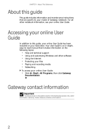
...-read manual that are for informational purposes only. Your User Guide is an in this section are specific to your model of Gateway notebook. CHAPTER 1: About This Reference About this guide This guide includes information and maintenance instructions that includes information on ...your online User Guide: • Click (Start), All Programs, then click Gateway Documentation. Label information varies by model, features ordered, and location. 2 For all other software • Using the Internet • Protecting your files &#...
...-read manual that are for informational purposes only. Your User Guide is an in this section are specific to your model of Gateway notebook. CHAPTER 1: About This Reference About this guide This guide includes information and maintenance instructions that includes information on ...your online User Guide: • Click (Start), All Programs, then click Gateway Documentation. Label information varies by model, features ordered, and location. 2 For all other software • Using the Internet • Protecting your files &#...
8512488 - Gateway Notebook Reference Guide R2
Page 9
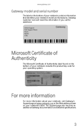
... found on the bottom of your notebook contains information that identifies your notebook's label. www.gateway.com Gateway model and serial number The label on the bottom of your operating system. The Support page also has links to additional Gateway documentation and detailed specifications. 3 For more information For more information about your notebook, visit...
... found on the bottom of your notebook contains information that identifies your notebook's label. www.gateway.com Gateway model and serial number The label on the bottom of your operating system. The Support page also has links to additional Gateway documentation and detailed specifications. 3 For more information For more information about your notebook, visit...
8512488 - Gateway Notebook Reference Guide R2
Page 14
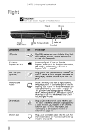
...;, MultiMediaCard™, RS-MultiMediaCard™, and Secure Digital™ cards. Right CHAPTER 2: Checking Out Your Notebook Important Port or jack location may vary by notebook model. The other end of the cable can be plugged into the memory card reader. Plug a dial-up modem" on page 45. For more information, see...
...;, MultiMediaCard™, RS-MultiMediaCard™, and Secure Digital™ cards. Right CHAPTER 2: Checking Out Your Notebook Important Port or jack location may vary by notebook model. The other end of the cable can be plugged into the memory card reader. Plug a dial-up modem" on page 45. For more information, see...
8512488 - Gateway Notebook Reference Guide R2
Page 16
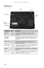
... Checking Out Your Notebook Bottom Battery Battery lock Battery latch Memory bay Customer care label Hard drive bay Online Support: Tech Support Phone: Hours: Model: S/No: Component Icon Hard drive bay Customer Care label Memory bay Battery latch Battery Battery lock Description The hard drive is not plugged into .... Includes the Customer Care contact information. For more information, see "Adding or replacing memory modules" on page 61. For more information, see "Gateway contact information" on page 100. For more information, see "Replacing the hard drive kit" on page 2.
... Checking Out Your Notebook Bottom Battery Battery lock Battery latch Memory bay Customer care label Hard drive bay Online Support: Tech Support Phone: Hours: Model: S/No: Component Icon Hard drive bay Customer Care label Memory bay Battery latch Battery Battery lock Description The hard drive is not plugged into .... Includes the Customer Care contact information. For more information, see "Adding or replacing memory modules" on page 61. For more information, see "Gateway contact information" on page 100. For more information, see "Replacing the hard drive kit" on page 2.


