8511725 - Gateway Service Guide
Page 3
Contents Replacing Notebook Components 1 Identifying the notebook model 2 Identifying components 3 Preparing your work space 4 Preventing static electricity discharge 5 Tape 5 Preparing the notebook 6 Removing the battery 6 Adding or replacing memory modules 7 Replacing the DVD drive 11 Replacing the cooling assembly 14 Replacing the processor 19 Replacing the IEEE 802.11 wireless card 22 Replacing the hard drive 26 Replacing the keyboard cover 29 Replacing the keyboard 31 Replacing the CMOS battery 36 Replacing the LCD panel assembly 38 Replacing the LCD panel inverter 42 ...
Contents Replacing Notebook Components 1 Identifying the notebook model 2 Identifying components 3 Preparing your work space 4 Preventing static electricity discharge 5 Tape 5 Preparing the notebook 6 Removing the battery 6 Adding or replacing memory modules 7 Replacing the DVD drive 11 Replacing the cooling assembly 14 Replacing the processor 19 Replacing the IEEE 802.11 wireless card 22 Replacing the hard drive 26 Replacing the keyboard cover 29 Replacing the keyboard 31 Replacing the CMOS battery 36 Replacing the LCD panel assembly 38 Replacing the LCD panel inverter 42 ...
8511725 - Gateway Service Guide
Page 5
Replacing Notebook Components • Identifying the notebook model • Identifying components • Preparing your work space • Preventing static electricity discharge • Preparing the notebook • Adding or replacing memory modules • Replacing the DVD drive • Replacing the cooling assembly • Replacing the processor • Replacing the IEEE 802.11 wireless card • Replacing the hard drive • Replacing the keyboard cover • Replacing the keyboard • Replacing the CMOS battery • Replacing the LCD panel assembly • ...
Replacing Notebook Components • Identifying the notebook model • Identifying components • Preparing your work space • Preventing static electricity discharge • Preparing the notebook • Adding or replacing memory modules • Replacing the DVD drive • Replacing the cooling assembly • Replacing the processor • Replacing the IEEE 802.11 wireless card • Replacing the hard drive • Replacing the keyboard cover • Replacing the keyboard • Replacing the CMOS battery • Replacing the LCD panel assembly • ...
8511725 - Gateway Service Guide
Page 6
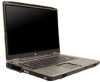
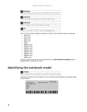
...Failure to follow the approved tasks for the notebook model may result in damage to channel.services@gateway.com. Online Support: Tech Support Phone: Hours: Model: S/No: support.gateway.com 2 It cannot be provided to individual users or consumers. Identifying the notebook model Caution It... the notebook contains information that you have suggestions regarding the content of the touchpad. Tip If you use the correct service guide for the following Gateway notebooks: • 6000 series • 6100 series • 6500 series • 6600 series • M360 • MX6000 series •...
...Failure to follow the approved tasks for the notebook model may result in damage to channel.services@gateway.com. Online Support: Tech Support Phone: Hours: Model: S/No: support.gateway.com 2 It cannot be provided to individual users or consumers. Identifying the notebook model Caution It... the notebook contains information that you have suggestions regarding the content of the touchpad. Tip If you use the correct service guide for the following Gateway notebooks: • 6000 series • 6100 series • 6500 series • 6600 series • M360 • MX6000 series •...
8511725 - Gateway Service Guide
Page 7
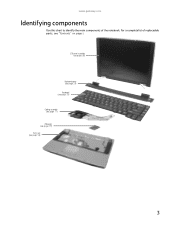
www.gateway.com Identifying components Use this chart to identify the main components of replaceable parts, see page 56) 3 For a complete list of the notebook. LCD panel assembly (see page 38) Keyboard cover (see page 29) Keyboard (see page 31) Cooling assembly (see page 11) Processor (see page 19) Palm rest (see "Contents" on page i.
www.gateway.com Identifying components Use this chart to identify the main components of replaceable parts, see page 56) 3 For a complete list of the notebook. LCD panel assembly (see page 38) Keyboard cover (see page 29) Keyboard (see page 31) Cooling assembly (see page 11) Processor (see page 19) Palm rest (see "Contents" on page i.
8511725 - Gateway Service Guide
Page 8
Replacing Notebook Components Preparing your work space Before performing maintenance on the notebook, make part identification easier. • Keep your work surface free from clutter and dust that may damage components. • Use a magnetized screwdriver for removing screws. • When removing components that your work surface, stand them onto the floor. • To help keep track of screws, try the following: • Place each component as you remove it. • Use bright lighting to prevent the screws from rolling off the table. 4 When reassembling the component, just remove ...
Replacing Notebook Components Preparing your work space Before performing maintenance on the notebook, make part identification easier. • Keep your work surface free from clutter and dust that may damage components. • Use a magnetized screwdriver for removing screws. • When removing components that your work surface, stand them onto the floor. • To help keep track of screws, try the following: • Place each component as you remove it. • Use bright lighting to prevent the screws from rolling off the table. 4 When reassembling the component, just remove ...
8511725 - Gateway Service Guide
Page 9
... procedures in this section. Both types of replacement tape should read and understand the information in this Gateway notebook: • Mylar, non-conductive tape is typically transparent, with the same type (conductivity) of tape. www.gateway.com Preventing static electricity discharge Warning To avoid exposure to a bare metal part of your workbench...
... procedures in this section. Both types of replacement tape should read and understand the information in this Gateway notebook: • Mylar, non-conductive tape is typically transparent, with the same type (conductivity) of tape. www.gateway.com Preventing static electricity discharge Warning To avoid exposure to a bare metal part of your workbench...

8511725 - Gateway Service Guide
Page 10
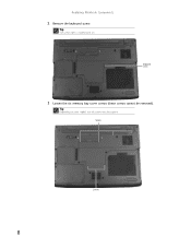
For more information, see "Removing the battery" on page 6. Removing the battery To remove the battery: 1 Turn the notebook over so the bottom is facing up. 2 Slide the battery lock to dangerous electrical voltages and moving parts, turn off the notebook and unplug the power cord, modem cable, and network cable. 4 Remove the battery. Replacing Notebook Components Preparing the notebook Warning To avoid exposure to the unlock position. 3 Slide and hold the battery release latch, then slide the battery out of the notebook. 6 To prepare the notebook for maintenance: 1 Make sure that ...
For more information, see "Removing the battery" on page 6. Removing the battery To remove the battery: 1 Turn the notebook over so the bottom is facing up. 2 Slide the battery lock to dangerous electrical voltages and moving parts, turn off the notebook and unplug the power cord, modem cable, and network cable. 4 Remove the battery. Replacing Notebook Components Preparing the notebook Warning To avoid exposure to the unlock position. 3 Slide and hold the battery release latch, then slide the battery out of the notebook. 6 To prepare the notebook for maintenance: 1 Make sure that ...
8511725 - Gateway Service Guide
Page 11
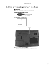
Tools you need to complete this task: Phillips #0 screwdriver Screws removed during this Gateway notebook. www.gateway.com Adding or replacing memory modules Important Use only memory modules designed for this task: 1 black (keyboard) Memory bay To add or replace memory modules: 1 Complete the steps in "Preparing the notebook" on page 6. 7
Tools you need to complete this task: Phillips #0 screwdriver Screws removed during this Gateway notebook. www.gateway.com Adding or replacing memory modules Important Use only memory modules designed for this task: 1 black (keyboard) Memory bay To add or replace memory modules: 1 Complete the steps in "Preparing the notebook" on page 6. 7
8511725 - Gateway Service Guide
Page 12
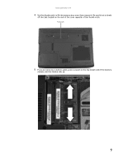
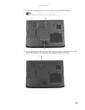
Keyboard screw 3 Loosen the six memory bay cover screws (these screws cannot be captive. Tip Depending on your model, not all screws may be removed). Screws Screws 8 Replacing Notebook Components 2 Remove the keyboard screw. Tip The screw hole is marked with a K.
Keyboard screw 3 Loosen the six memory bay cover screws (these screws cannot be captive. Tip Depending on your model, not all screws may be removed). Screws Screws 8 Replacing Notebook Components 2 Remove the keyboard screw. Tip The screw hole is marked with a K.
8511725 - Gateway Service Guide
Page 13
Be careful not to lift the memory bay cover, then remove it. Thumb notch 5 If you are removing a module, gently press outward on the end of the cover opposite of the memory module until the module tilts up. 9 www.gateway.com 4 Use the thumb notch to break off the tabs located on the clip at each end of the thumb notch.
Be careful not to lift the memory bay cover, then remove it. Thumb notch 5 If you are removing a module, gently press outward on the end of the cover opposite of the memory module until the module tilts up. 9 www.gateway.com 4 Use the thumb notch to break off the tabs located on the clip at each end of the thumb notch.

8511725 - Gateway Service Guide
Page 14
If the module does not fit, make sure that the notch in the module lines up with a K. 10 Replacing Notebook Components 6 Pull the memory module out of the slot. 7 Hold the new or replacement module at a 30-degree angle and press it can only be inserted in the memory bay. 8 Replace the memory bay cover, then tighten the cover screws. 9 Replace the keyboard screw. Tip The screw hole is keyed so it into the empty memory slot. This module is marked with the tab in one direction.
If the module does not fit, make sure that the notch in the module lines up with a K. 10 Replacing Notebook Components 6 Pull the memory module out of the slot. 7 Hold the new or replacement module at a 30-degree angle and press it can only be inserted in the memory bay. 8 Replace the memory bay cover, then tighten the cover screws. 9 Replace the keyboard screw. Tip The screw hole is keyed so it into the empty memory slot. This module is marked with the tab in one direction.
8511725 - Gateway Service Guide
Page 15
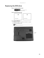
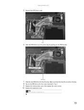
Keyboard screw 11 www.gateway.com Replacing the DVD drive Tools you need to complete this task: Phillips #0 screwdriver Screws removed during this task: 1 black (keyboard) 1 black (DVD drive) To replace the DVD drive: 1 Complete the steps in "Preparing the notebook" on page 6. 2 Remove the keyboard screw. Tip The screw hole is marked with a K.
Keyboard screw 11 www.gateway.com Replacing the DVD drive Tools you need to complete this task: Phillips #0 screwdriver Screws removed during this task: 1 black (keyboard) 1 black (DVD drive) To replace the DVD drive: 1 Complete the steps in "Preparing the notebook" on page 6. 2 Remove the keyboard screw. Tip The screw hole is marked with a K.
8511725 - Gateway Service Guide
Page 16
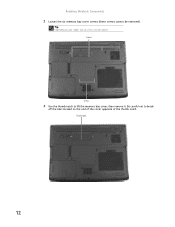
Replacing Notebook Components 3 Loosen the six memory bay cover screws (these screws cannot be captive. Screws Screws 4 Use the thumb notch to break off the tabs located on your model, not all screws may be removed). Be careful not to lift the memory bay cover, then remove it. Thumb notch 12 Tip Depending on the end of the cover opposite of the thumb notch.
Replacing Notebook Components 3 Loosen the six memory bay cover screws (these screws cannot be captive. Screws Screws 4 Use the thumb notch to break off the tabs located on your model, not all screws may be removed). Be careful not to lift the memory bay cover, then remove it. Thumb notch 12 Tip Depending on the end of the cover opposite of the thumb notch.
8511725 - Gateway Service Guide
Page 17
Make sure that the drive fits securely in the bay. 8 Secure the DVD drive with a K. 13 Tip The screw hole is marked with the screw removed in Step 5. 9 Replace the memory bay cover, then tighten the cover screws. 10 Replace the keyboard screw. DVD bracket 7 Slide the new DVD drive into the drive bay. www.gateway.com 5 Remove the DVD drive screw. Screw 6 Slide the DVD drive out of the drive bay by pushing on the DVD bracket.
Make sure that the drive fits securely in the bay. 8 Secure the DVD drive with a K. 13 Tip The screw hole is marked with the screw removed in Step 5. 9 Replace the memory bay cover, then tighten the cover screws. 10 Replace the keyboard screw. DVD bracket 7 Slide the new DVD drive into the drive bay. www.gateway.com 5 Remove the DVD drive screw. Screw 6 Slide the DVD drive out of the drive bay by pushing on the DVD bracket.

8511725 - Gateway Service Guide
Page 18
Keyboard screw 14 Tip The screw hole is marked with a K. Replacing Notebook Components Replacing the cooling assembly Tools you need to complete this task: Phillips #0 screwdriver Additional materials you may need to complete this task: • X-23-7762 thermal grease Screws removed during this task: 1 black (keyboard) To replace the cooling assembly: 1 Complete the steps in "Preparing the notebook" on page 6. 2 Remove the keyboard screw.
Keyboard screw 14 Tip The screw hole is marked with a K. Replacing Notebook Components Replacing the cooling assembly Tools you need to complete this task: Phillips #0 screwdriver Additional materials you may need to complete this task: • X-23-7762 thermal grease Screws removed during this task: 1 black (keyboard) To replace the cooling assembly: 1 Complete the steps in "Preparing the notebook" on page 6. 2 Remove the keyboard screw.
8511725 - Gateway Service Guide
Page 19
Thumb notch 15 Be careful not to lift the memory bay cover, then remove it. Screws Screws 4 Use the thumb notch to break off the tabs located on your model, not all screws may be removed). Tip Depending on the end of the cover opposite of the thumb notch. www.gateway.com 3 Loosen the six memory bay cover screws (these screws cannot be captive.
Thumb notch 15 Be careful not to lift the memory bay cover, then remove it. Screws Screws 4 Use the thumb notch to break off the tabs located on your model, not all screws may be removed). Tip Depending on the end of the cover opposite of the thumb notch. www.gateway.com 3 Loosen the six memory bay cover screws (these screws cannot be captive.
8511725 - Gateway Service Guide
Page 20
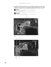
Replacing Notebook Components 5 Loosen the three or four screws (these screws cannot be removed) that secure the cooling assembly to each screw and loosen the screws in reverse numerical order. Important The number of screws varies by model. Screw Screw Screw -OR- Caution When loosening the cooling assembly's screws in the numbered holes, loosen them in reverse numerical order (start with 4, then 3, then 2, then 1). Use the numbers stamped in the metal next to the system board. Screw Screw Screw Screw 16
Replacing Notebook Components 5 Loosen the three or four screws (these screws cannot be removed) that secure the cooling assembly to each screw and loosen the screws in reverse numerical order. Important The number of screws varies by model. Screw Screw Screw -OR- Caution When loosening the cooling assembly's screws in the numbered holes, loosen them in reverse numerical order (start with 4, then 3, then 2, then 1). Use the numbers stamped in the metal next to the system board. Screw Screw Screw Screw 16
8511725 - Gateway Service Guide
Page 21
The cooling assembly cable is attached to the system board at this point. www.gateway.com 6 .At the same time as you with thermal grease already applied, place new thermal grease on the processor. Caution The cooling assembly cable is ...
The cooling assembly cable is attached to the system board at this point. www.gateway.com 6 .At the same time as you with thermal grease already applied, place new thermal grease on the processor. Caution The cooling assembly cable is ...
8511725 - Gateway Service Guide
Page 22
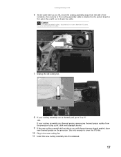
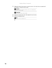
Caution When tightening the cooling assembly's screws in the numbered holes, tighten them . Tip The screw hole is marked with the numbers 1 through 4 next to them in numerical order. Replacing Notebook Components 12 Tighten the three or four screws, in numerical order, in the holes that are stamped with a K. 18 Important The number of screws varies by model. 13 Replace the memory bay cover, then tighten the cover screws. 14 Replace the keyboard screw.
Caution When tightening the cooling assembly's screws in the numbered holes, tighten them . Tip The screw hole is marked with the numbers 1 through 4 next to them in numerical order. Replacing Notebook Components 12 Tighten the three or four screws, in numerical order, in the holes that are stamped with a K. 18 Important The number of screws varies by model. 13 Replace the memory bay cover, then tighten the cover screws. 14 Replace the keyboard screw.
8511725 - Gateway Service Guide
Page 23
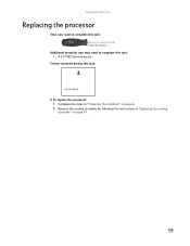
www.gateway.com Replacing the processor Tools you need to complete this task: Phillips #0 screwdriver Additional materials you may need to complete this task: • X-23-7762 thermal grease Screws removed during this task: 1 black (keyboard) To replace the processor: 1 Complete the steps in "Preparing the notebook" on page 6. 2 Remove the cooling assembly by following the instructions in "Replacing the cooling assembly" on page 14. 19
www.gateway.com Replacing the processor Tools you need to complete this task: Phillips #0 screwdriver Additional materials you may need to complete this task: • X-23-7762 thermal grease Screws removed during this task: 1 black (keyboard) To replace the processor: 1 Complete the steps in "Preparing the notebook" on page 6. 2 Remove the cooling assembly by following the instructions in "Replacing the cooling assembly" on page 14. 19