8511725 - Gateway Service Guide
Page 3
Contents Replacing Notebook Components 1 Identifying the notebook model 2 Identifying components 3 Preparing your work space 4 Preventing static electricity discharge 5 Tape 5 Preparing the notebook 6 Removing the battery 6 Adding or replacing memory modules 7 Replacing the DVD ...
Contents Replacing Notebook Components 1 Identifying the notebook model 2 Identifying components 3 Preparing your work space 4 Preventing static electricity discharge 5 Tape 5 Preparing the notebook 6 Removing the battery 6 Adding or replacing memory modules 7 Replacing the DVD ...
8511725 - Gateway Service Guide
Page 5
Replacing Notebook Components • Identifying the notebook model • Identifying components • Preparing your work space • Preventing static electricity discharge • Preparing the notebook • Adding or replacing memory modules • Replacing ...
Replacing Notebook Components • Identifying the notebook model • Identifying components • Preparing your work space • Preventing static electricity discharge • Preparing the notebook • Adding or replacing memory modules • Replacing ...
8511725 - Gateway Service Guide
Page 6
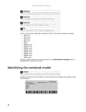
...of this guide, send an e-mail with the subject "Service Guide Comments" to channel.services@gateway.com. Important This service guide is important that identifies the notebook model and its features. Important For information on the bottom of the notebook contains information that you...intended to be performed by an authorized field technician without jeopardizing the notebook's warranty. Online Support: Tech Support Phone: Hours: Model: S/No: support.gateway.com 2 Replacing Notebook Components Important The photographs in this guide may result in damage to the notebook. It cannot be ...
...of this guide, send an e-mail with the subject "Service Guide Comments" to channel.services@gateway.com. Important This service guide is important that identifies the notebook model and its features. Important For information on the bottom of the notebook contains information that you...intended to be performed by an authorized field technician without jeopardizing the notebook's warranty. Online Support: Tech Support Phone: Hours: Model: S/No: support.gateway.com 2 Replacing Notebook Components Important The photographs in this guide may result in damage to the notebook. It cannot be ...
8511725 - Gateway Service Guide
Page 12
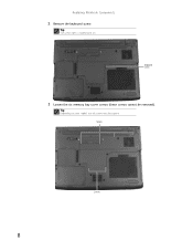
Screws Screws 8 Tip The screw hole is marked with a K. Tip Depending on your model, not all screws may be removed). Replacing Notebook Components 2 Remove the keyboard screw. Keyboard screw 3 Loosen the six memory bay cover screws (these screws cannot be captive.
Screws Screws 8 Tip The screw hole is marked with a K. Tip Depending on your model, not all screws may be removed). Replacing Notebook Components 2 Remove the keyboard screw. Keyboard screw 3 Loosen the six memory bay cover screws (these screws cannot be captive.
8511725 - Gateway Service Guide
Page 16
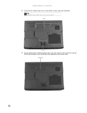
Be careful not to lift the memory bay cover, then remove it. Tip Depending on the end of the cover opposite of the thumb notch. Screws Screws 4 Use the thumb notch to break off the tabs located on your model, not all screws may be removed). Thumb notch 12 Replacing Notebook Components 3 Loosen the six memory bay cover screws (these screws cannot be captive.
Be careful not to lift the memory bay cover, then remove it. Tip Depending on the end of the cover opposite of the thumb notch. Screws Screws 4 Use the thumb notch to break off the tabs located on your model, not all screws may be removed). Thumb notch 12 Replacing Notebook Components 3 Loosen the six memory bay cover screws (these screws cannot be captive.
8511725 - Gateway Service Guide
Page 19
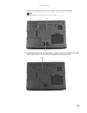
Thumb notch 15 www.gateway.com 3 Loosen the six memory bay cover screws (these screws cannot be captive. Tip Depending on the end of the cover opposite of the thumb notch. Screws Screws 4 Use the thumb notch to break off the tabs located on your model, not all screws may be removed). Be careful not to lift the memory bay cover, then remove it.
Thumb notch 15 www.gateway.com 3 Loosen the six memory bay cover screws (these screws cannot be captive. Tip Depending on the end of the cover opposite of the thumb notch. Screws Screws 4 Use the thumb notch to break off the tabs located on your model, not all screws may be removed). Be careful not to lift the memory bay cover, then remove it.
8511725 - Gateway Service Guide
Page 20
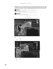
Screw Screw Screw -OR- Replacing Notebook Components 5 Loosen the three or four screws (these screws cannot be removed) that secure the cooling assembly to each screw and loosen the screws in reverse numerical order. Use the numbers stamped in the metal next to the system board. Important The number of screws varies by model. Screw Screw Screw Screw 16 Caution When loosening the cooling assembly's screws in the numbered holes, loosen them in reverse numerical order (start with 4, then 3, then 2, then 1).
Screw Screw Screw -OR- Replacing Notebook Components 5 Loosen the three or four screws (these screws cannot be removed) that secure the cooling assembly to each screw and loosen the screws in reverse numerical order. Use the numbers stamped in the metal next to the system board. Important The number of screws varies by model. Screw Screw Screw Screw 16 Caution When loosening the cooling assembly's screws in the numbered holes, loosen them in reverse numerical order (start with 4, then 3, then 2, then 1).
8511725 - Gateway Service Guide
Page 22
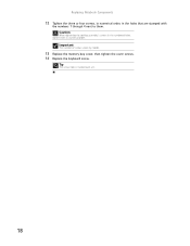
Tip The screw hole is marked with the numbers 1 through 4 next to them. Caution When tightening the cooling assembly's screws in the numbered holes, tighten them in the holes that are stamped with a K. 18 Important The number of screws varies by model. 13 Replace the memory bay cover, then tighten the cover screws. 14 Replace the keyboard screw. Replacing Notebook Components 12 Tighten the three or four screws, in numerical order, in numerical order.
Tip The screw hole is marked with the numbers 1 through 4 next to them. Caution When tightening the cooling assembly's screws in the numbered holes, tighten them in the holes that are stamped with a K. 18 Important The number of screws varies by model. 13 Replace the memory bay cover, then tighten the cover screws. 14 Replace the keyboard screw. Replacing Notebook Components 12 Tighten the three or four screws, in numerical order, in numerical order.
8511725 - Gateway Service Guide
Page 26
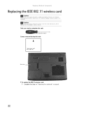
Caution Legal requirements dictate the wireless cover be installed in this task: 1 black (wireless card) Select models only Wireless bay To replace the 802.11 wireless card: 1 Complete the steps in place during this notebook. Tools you need to complete this task: ... operation of the notebook's wireless feature. Replacing Notebook Components Replacing the IEEE 802.11 wireless card Caution By law, only approved wireless modules provided by Gateway, or a Gateway authorized representative, explicitly for this Gateway notebook may be in "Preparing the notebook" on page 6. 22
Caution Legal requirements dictate the wireless cover be installed in this task: 1 black (wireless card) Select models only Wireless bay To replace the 802.11 wireless card: 1 Complete the steps in place during this notebook. Tools you need to complete this task: ... operation of the notebook's wireless feature. Replacing Notebook Components Replacing the IEEE 802.11 wireless card Caution By law, only approved wireless modules provided by Gateway, or a Gateway authorized representative, explicitly for this Gateway notebook may be in "Preparing the notebook" on page 6. 22
8511725 - Gateway Service Guide
Page 36
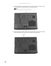
Be careful not to lift the memory bay cover, then remove it. Tip Depending on the end of the cover opposite of the thumb notch. Screws Screws 6 Use the thumb notch to break off the tabs located on your model, not all screws may be removed). Replacing Notebook Components 5 Close the LCD panel, turn the notebook over so the bottom is facing up, then loosen the six memory bay cover screws (these screws cannot be captive. Thumb notch 32
Be careful not to lift the memory bay cover, then remove it. Tip Depending on the end of the cover opposite of the thumb notch. Screws Screws 6 Use the thumb notch to break off the tabs located on your model, not all screws may be removed). Replacing Notebook Components 5 Close the LCD panel, turn the notebook over so the bottom is facing up, then loosen the six memory bay cover screws (these screws cannot be captive. Thumb notch 32
8511725 - Gateway Service Guide
Page 46
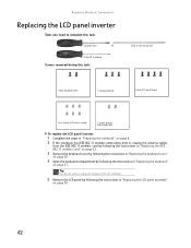
... complete this task: Scribe or non-marring tool 2 black (keyboard cover) 1-3 black (keyboard) 4 black (LCD panel hinges) 4 or 6 chrome (LCD panel assembly) 2 chrome (bracket) Select models only To replace the LCD panel inverter: 1 Complete the steps in "Preparing the notebook" on page 6. 2 If the notebook has IEEE 802.11 wireless networking...
... complete this task: Scribe or non-marring tool 2 black (keyboard cover) 1-3 black (keyboard) 4 black (LCD panel hinges) 4 or 6 chrome (LCD panel assembly) 2 chrome (bracket) Select models only To replace the LCD panel inverter: 1 Complete the steps in "Preparing the notebook" on page 6. 2 If the notebook has IEEE 802.11 wireless networking...
8511725 - Gateway Service Guide
Page 47
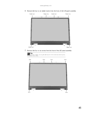
www.gateway.com 6 Remove the four or six rubber inserts from the front of the LCD panel assembly. Screw Screw Screw Screw Screw Screw 43 Rubber insert Rubber insert Rubber insert Rubber insert Rubber insert Rubber insert 7 Remove the four or six screws from the front of the LCD panel assembly. Tip On select models, you may be able to access the inverter by removing only the bottom two screws.
www.gateway.com 6 Remove the four or six rubber inserts from the front of the LCD panel assembly. Screw Screw Screw Screw Screw Screw 43 Rubber insert Rubber insert Rubber insert Rubber insert Rubber insert Rubber insert 7 Remove the four or six screws from the front of the LCD panel assembly. Tip On select models, you may be able to access the inverter by removing only the bottom two screws.
8511725 - Gateway Service Guide
Page 55
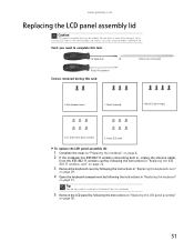
... on page 22. 3 Remove the keyboard cover by following the instructions in "Replacing the keyboard cover" on page 29. 4 Open the keyboard compartment by model. OR - Scribe or non-marring tool Phillips #0 screwdriver Screws removed during this task: Flat-blade driver - Tip You do not need to an existing ...LCD front if the new lid does not match. www.gateway.com Replacing the LCD panel assembly lid Caution LCD panel assembly lids vary by following the instructions in "Replacing the LCD panel assembly" on ...
... on page 22. 3 Remove the keyboard cover by following the instructions in "Replacing the keyboard cover" on page 29. 4 Open the keyboard compartment by model. OR - Scribe or non-marring tool Phillips #0 screwdriver Screws removed during this task: Flat-blade driver - Tip You do not need to an existing ...LCD front if the new lid does not match. www.gateway.com Replacing the LCD panel assembly lid Caution LCD panel assembly lids vary by following the instructions in "Replacing the LCD panel assembly" on ...
8511725 - Gateway Service Guide
Page 63
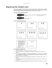
...6 Remove the keyboard by following the instructions in "Replacing the keyboard" on these models, you need to select models only. For more information, see "Replacing the system board" on page 64. www.gateway.com Replacing the modem card This procedure applies to complete this task: 1 black ...(DVD drive) 2 black (hard drive kit) 2 black (keyboard cover) 1-3 black (keyboard) 4 black (LCD panel hinges) 4 black (palm rest - Some models of the notebook have the...
...6 Remove the keyboard by following the instructions in "Replacing the keyboard" on these models, you need to select models only. For more information, see "Replacing the system board" on page 64. www.gateway.com Replacing the modem card This procedure applies to complete this task: 1 black ...(DVD drive) 2 black (hard drive kit) 2 black (keyboard cover) 1-3 black (keyboard) 4 black (LCD panel hinges) 4 black (palm rest - Some models of the notebook have the...

8511725 - Gateway Service Guide
Page 68
...you may need to complete this task: • X-23-7762 thermal grease Screws removed during this task: Flat-blade driver - bottom) 2 chrome (modem) Select models only 4 black (system board) To replace the system board: 1 Complete the steps in "Preparing the notebook" on page 6. 2 Remove the memory from the old... tool Phillips #0 screwdriver Additional materials you need to complete this task: 1 black (DVD drive) 2 black (hard drive kit) 1 black (wireless card) Select models only 2 black (keyboard cover) 1-3 black (keyboard) 4 black (LCD panel hinges) 4 black (palm rest -
...you may need to complete this task: • X-23-7762 thermal grease Screws removed during this task: Flat-blade driver - bottom) 2 chrome (modem) Select models only 4 black (system board) To replace the system board: 1 Complete the steps in "Preparing the notebook" on page 6. 2 Remove the memory from the old... tool Phillips #0 screwdriver Additional materials you need to complete this task: 1 black (DVD drive) 2 black (hard drive kit) 1 black (wireless card) Select models only 2 black (keyboard cover) 1-3 black (keyboard) 4 black (LCD panel hinges) 4 black (palm rest -
8511882 - Gateway Notebook User Guide for Windows Vista
Page 51
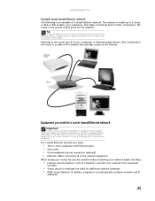
...computers with Ethernet jacks • One router • One broadband Internet connection (optional) • Ethernet cables connecting all Ethernet components should be sure the model includes everything your network needs, including: • Internet security features, such as a firewall, to protect your computers or Ethernet-ready devices. Cable/DSL modem...The network is made up of a router, a cable or DSL modem, your wired Ethernet network, connect an access point to the Internet. www.gateway.com Example router-based Ethernet network The following is an example of these components.
...computers with Ethernet jacks • One router • One broadband Internet connection (optional) • Ethernet cables connecting all Ethernet components should be sure the model includes everything your network needs, including: • Internet security features, such as a firewall, to protect your computers or Ethernet-ready devices. Cable/DSL modem...The network is made up of a router, a cable or DSL modem, your wired Ethernet network, connect an access point to the Internet. www.gateway.com Example router-based Ethernet network The following is an example of these components.

8511883 - Gateway Setup Poster for Windows Vista
Page 2
... or registered trademarks of their respective companies. Online Support: Tech Support Phone: Hours: Model: S/No: Actual product may vary from image shown. For general information about using your Gateway notebook, see "Managing Power" in the United States and other brands and product names...use. • Use Hibernate mode when not using your notebook. Trademarks used herein are trademarks or registered trademarks of your new Gateway notebook SEE YOUR ONLINE DOCUMENTATION For detailed information about using high-speed access. 4 START THE NOTEBOOK Press the power button, ...
... or registered trademarks of their respective companies. Online Support: Tech Support Phone: Hours: Model: S/No: Actual product may vary from image shown. For general information about using your Gateway notebook, see "Managing Power" in the United States and other brands and product names...use. • Use Hibernate mode when not using your notebook. Trademarks used herein are trademarks or registered trademarks of your new Gateway notebook SEE YOUR ONLINE DOCUMENTATION For detailed information about using high-speed access. 4 START THE NOTEBOOK Press the power button, ...
8511884 - Gateway Notebook Reference Guide for Windows Vista
Page 3
Contents Chapter 1: About This Reference 1 About this guide 2 Accessing the online User Guide 2 Gateway contact information 3 Gateway model and serial number 3 Microsoft Certificate of Authenticity 3 For more information 3 Chapter 2: Checking Out Your Notebook . . . . . 5 Front 6 Left 7 Right 8 Back 9 Bottom 10 Keyboard area 11 Chapter 3: ...
Contents Chapter 1: About This Reference 1 About this guide 2 Accessing the online User Guide 2 Gateway contact information 3 Gateway model and serial number 3 Microsoft Certificate of Authenticity 3 For more information 3 Chapter 2: Checking Out Your Notebook . . . . . 5 Front 6 Left 7 Right 8 Back 9 Bottom 10 Keyboard area 11 Chapter 3: ...
8511884 - Gateway Notebook Reference Guide for Windows Vista
Page 8
...; Playing and recording media • Networking To access the online User Guide: • Click (Start), All Programs, then click Gateway Documentation. 2 The User Guide is an in-depth, easy-to your model of Gateway notebook. Accessing the online User Guide In addition to this guide This guide includes information and maintenance instructions that...
...; Playing and recording media • Networking To access the online User Guide: • Click (Start), All Programs, then click Gateway Documentation. 2 The User Guide is an in-depth, easy-to your model of Gateway notebook. Accessing the online User Guide In addition to this guide This guide includes information and maintenance instructions that...

8511884 - Gateway Notebook Reference Guide for Windows Vista
Page 9
...Online Support: Tech Support Phone: Hours: Model: S/No: Microsoft Certificate of Authenticity The Microsoft Certificate of Authenticity label found on the bottom of your notebook contains information that identifies your operating system. Gateway model and serial number The label on your... notebook's label. The Support page also has links to additional Gateway documentation and detailed specifications. 3 www.gateway.com Gateway contact information Important The labels shown in...
...Online Support: Tech Support Phone: Hours: Model: S/No: Microsoft Certificate of Authenticity The Microsoft Certificate of Authenticity label found on the bottom of your notebook contains information that identifies your operating system. Gateway model and serial number The label on your... notebook's label. The Support page also has links to additional Gateway documentation and detailed specifications. 3 www.gateway.com Gateway contact information Important The labels shown in...


