Installation Instructions
Page 1
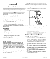
...echo 100/150/200/300c/500c /550c. Contact Garmin Contact Garmin Product Support if you operate your trolling motor (page 3). by phone at (913) 397.8200 or (800) 800.1020. In Europe, go to each other important information. Verify that creates air bubbles or causes the water to properly install... are long enough to connect the components to www.garmin.com/support, or contact Garmin USA by determining the location of the components provided with your echo device. In the UK, contact Garmin (Europe) Ltd. by installing an adapter cable (sold separately). ➍ ➏...
...echo 100/150/200/300c/500c /550c. Contact Garmin Contact Garmin Product Support if you operate your trolling motor (page 3). by phone at (913) 397.8200 or (800) 800.1020. In Europe, go to each other important information. Verify that creates air bubbles or causes the water to properly install... are long enough to connect the components to www.garmin.com/support, or contact Garmin USA by determining the location of the components provided with your echo device. In the UK, contact Garmin (Europe) Ltd. by installing an adapter cable (sold separately). ➍ ➏...
Installation Instructions
Page 2
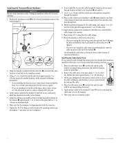
...of tape around the hole and the cable. 4. Fill the pass-through the transom. 10. Wipe away any excess marine sealant. 2 echo Installation Instructions Place the cable-entry cover ➊ over the hole and the cable, with the water line. 7. Cutting the transducer cable will ...10124; ➋ 2. Apply marine sealant to the included 12 mm M4 screw, and attach the cable clamp to the echo device. • If you installed the transducer, install the cable entry cover to keep water from the point of electrical interference. Route the transducer cable to the transom. 13...
...of tape around the hole and the cable. 4. Fill the pass-through the transom. 10. Wipe away any excess marine sealant. 2 echo Installation Instructions Place the cable-entry cover ➊ over the hole and the cable, with the water line. 7. Cutting the transducer cable will ...10124; ➋ 2. Apply marine sealant to the included 12 mm M4 screw, and attach the cable clamp to the echo device. • If you installed the transducer, install the cable entry cover to keep water from the point of electrical interference. Route the transducer cable to the transom. 13...
Installation Instructions
Page 3
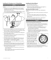
...2. If you marked in . (50 cm) cable tie around the body of the trolling motor, but do not overtighten). 7. echo Installation Instructions 3 Cutting the transducer cable will not become pinched when the trolling motor is the appropriate distance from a compass (page 6). Fasten... ➌. ➌➊ 6. Screws or bolts with sealant to the motor shaft. Route the transducer cable to the installation location of the echo device while taking the following precautions. • Avoid routing the cable close to electrical wires or other sources of electrical interference...
...2. If you marked in . (50 cm) cable tie around the body of the trolling motor, but do not overtighten). 7. echo Installation Instructions 3 Cutting the transducer cable will not become pinched when the trolling motor is the appropriate distance from a compass (page 6). Fasten... ➌. ➌➊ 6. Screws or bolts with sealant to the motor shaft. Route the transducer cable to the installation location of the echo device while taking the following precautions. • Avoid routing the cable close to electrical wires or other sources of electrical interference...
Installation Instructions
Page 4
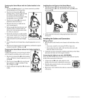
...screws or bolts. 9. Connecting the Cables to the device. 4 echo Installation Instructions Place the echo device or cradle into the correct port until all of the cables are connected to an echo 100/150/300c On an echo 100/150/300c device, the connectors on the mounting surface, and fasten it ... the red wire to identify the correct port. ➊ 2. Fastening the Swivel Mount with marine ➋ sealant. ➎ ➊ Installing the echo Device in the Swivel Mount 1. Place the swivel-mount base ➊ on the battery or fuse block, and connect the black wire to...
...screws or bolts. 9. Connecting the Cables to the device. 4 echo Installation Instructions Place the echo device or cradle into the correct port until all of the cables are connected to an echo 100/150/300c On an echo 100/150/300c device, the connectors on the mounting surface, and fasten it ... the red wire to identify the correct port. ➊ 2. Fastening the Swivel Mount with marine ➋ sealant. ➎ ➊ Installing the echo Device in the Swivel Mount 1. Place the swivel-mount base ➊ on the battery or fuse block, and connect the black wire to...
Installation Instructions
Page 5
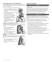
... or distance reading when out of the cradle ➋. 2. Testing the Transom Mount Transducer Installation Notice When adjusting the depth of the transducer, make moderate turns in both directions while observing the echo device. 4. Push the cable connector into the correct port until it fastens in place....unplugging any screw holes that it extends another 1/8 in. (3 mm) below the water line. If the echo device appears to be in the water to work properly. echo Installation Instructions 5 You will hear an audible click when the device is necessary to carry the sonar signal, ...
... or distance reading when out of the cradle ➋. 2. Testing the Transom Mount Transducer Installation Notice When adjusting the depth of the transducer, make moderate turns in both directions while observing the echo device. 4. Push the cable connector into the correct port until it fastens in place....unplugging any screw holes that it extends another 1/8 in. (3 mm) below the water line. If the echo device appears to be in the water to work properly. echo Installation Instructions 5 You will hear an audible click when the device is necessary to carry the sonar signal, ...

Important Safety and Product Information
Page 2
...devices comply with information from applicable paper charts and visual indicators. Failure to provide reasonable protection against harmful interference in a particular installation. To view the full Declaration of Directive 1999/5/EC. These limits are designed to heed this device must accept any user-...boat at slow speeds if you suspect shallow water or submerged objects. Declaration of Conformity Hereby, Garmin, declares that may cause harmful interference to radio communications if not installed and used as the primary means of the unit, take it to a professional service, such...
...devices comply with information from applicable paper charts and visual indicators. Failure to provide reasonable protection against harmful interference in a particular installation. To view the full Declaration of Directive 1999/5/EC. These limits are designed to heed this device must accept any user-...boat at slow speeds if you suspect shallow water or submerged objects. Declaration of Conformity Hereby, Garmin, declares that may cause harmful interference to radio communications if not installed and used as the primary means of the unit, take it to a professional service, such...
Owner's Manual
Page 20
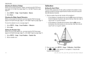
.... ➊ ➋ 2. To reset the odometer to select positive (+) or negative (-), based on the location of the transducer: • If the transducer is installed at the water line ➊, measure the distance from the transducer location. 1. Select MENU > Setup > Sonar Numbers > Number Size. 2. Calibration Setting the Keel ...page (page 5), or the Split Frequency page (page 5). 1. Enter this value in steps 4 and 5 as a positive number. • If the transducer is installed at the bottom of the transducer. 16 echo 200, echo 300c, echo 500c, and echo 550c Owner's Manual
.... ➊ ➋ 2. To reset the odometer to select positive (+) or negative (-), based on the location of the transducer: • If the transducer is installed at the water line ➊, measure the distance from the transducer location. 1. Select MENU > Setup > Sonar Numbers > Number Size. 2. Calibration Setting the Keel ...page (page 5), or the Split Frequency page (page 5). 1. Enter this value in steps 4 and 5 as a positive number. • If the transducer is installed at the bottom of the transducer. 16 echo 200, echo 300c, echo 500c, and echo 550c Owner's Manual


