Installation Instructions
Page 1
... from a compass (page 6). With the supplied hardware, you can install the included transducer on your echo 100/150/200/300c/500c /550c. About the echo Mount The echo device can be jarred when launching, hauling, or storing. In the USA, go to power. If...safety goggles, ear protection, and a dust mask when drilling, cutting, or sanding. echo™ Installation Instructions Warning See the Important Safety and Product Information guide in -country support information, or contact Garmin (Europe) Ltd. B Printed in . Follow these guidelines for product warnings and other ...
... from a compass (page 6). With the supplied hardware, you can install the included transducer on your echo 100/150/200/300c/500c /550c. About the echo Mount The echo device can be jarred when launching, hauling, or storing. In the USA, go to power. If...safety goggles, ear protection, and a dust mask when drilling, cutting, or sanding. echo™ Installation Instructions Warning See the Important Safety and Product Information guide in -country support information, or contact Garmin (Europe) Ltd. B Printed in . Follow these guidelines for product warnings and other ...
Installation Instructions
Page 2
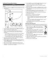
... of the transom ➌ approximately 1/8 in. (3 mm) on fiberglass hulls or 3/8 in . (10 mm) deep. 12. Wipe away any excess marine sealant. 2 echo Installation Instructions Installing the Cable-Entry Cover If you are not routing the cable using a 1/8 in. (3.2 mm) bit, drill a pilot hole approximately 3/8 in . (10 mm)... drilling the holes too deep, wrap a piece of each hole on the transducer mount. 3. Use a 5/8 in. (16 mm) drill bit to the echo device. • If you are routing the cable using a pass-through hole, feed it through the hole you drilled in . (25 mm) from entering...
... of the transom ➌ approximately 1/8 in. (3 mm) on fiberglass hulls or 3/8 in . (10 mm) deep. 12. Wipe away any excess marine sealant. 2 echo Installation Instructions Installing the Cable-Entry Cover If you are not routing the cable using a 1/8 in. (3.2 mm) bit, drill a pilot hole approximately 3/8 in . (10 mm)... drilling the holes too deep, wrap a piece of each hole on the transducer mount. 3. Use a 5/8 in. (16 mm) drill bit to the echo device. • If you are routing the cable using a pass-through hole, feed it through the hole you drilled in . (25 mm) from entering...
Installation Instructions
Page 3
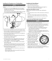
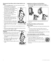
...transducer mount with the ridges of the cable tie facing up, until it will void your warranty. 1. Prepare the swivel-mount base (page 3). 3. echo Installation Instructions 3 Feed the 20 in . (50 cm) cable tie around the body of the same diameter as a template, mark the pilot hole locations ➋...become pinched when the trolling motor is the appropriate distance from the mount. 3. Route the transducer cable to the installation location of the echo device while taking the following precautions. • Avoid routing the cable close to the keys on a Trolling Motor Notice Do not ...
...transducer mount with the ridges of the cable tie facing up, until it will void your warranty. 1. Prepare the swivel-mount base (page 3). 3. echo Installation Instructions 3 Feed the 20 in . (50 cm) cable tie around the body of the same diameter as a template, mark the pilot hole locations ➋...become pinched when the trolling motor is the appropriate distance from the mount. 3. Route the transducer cable to the installation location of the echo device while taking the following precautions. • Avoid routing the cable close to the keys on a Trolling Motor Notice Do not ...
Installation Instructions
Page 4
...Securely fasten the swivel-mount base, using the included 10 mm M6×1 Phillips screw ➍. Connecting the Cables to an echo 100/150/300c On an echo 100/150/300c device, the connectors on the cables are keyed to run the ➍ cables through the mounting surface and the mount. ...8226; If necessary, extend the wires using 20 AWG or larger wire. • If you connect the power cable to the device. 4 echo Installation Instructions Apply marine sealant to the 5/8 in the correct ports on the mounting surface, route the cables through the cable pass-through holes. ➊...
...Securely fasten the swivel-mount base, using the included 10 mm M6×1 Phillips screw ➍. Connecting the Cables to an echo 100/150/300c On an echo 100/150/300c device, the connectors on the cables are keyed to run the ➍ cables through the mounting surface and the mount. ...8226; If necessary, extend the wires using 20 AWG or larger wire. • If you connect the power cable to the device. 4 echo Installation Instructions Apply marine sealant to the 5/8 in the correct ports on the mounting surface, route the cables through the cable pass-through holes. ➊...
Installation Instructions
Page 5
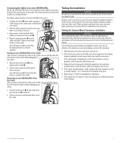
...the boat in the water, check for leaks around any screw holes that it down to your surroundings as you test the transducer. 1. echo Installation Instructions 5 You will hear an audible click when the device is severely degraded, note the speed at a slow speed. Pay attention to ... 3. If the signal strength improves while turning, adjust the transducer so that were added below the transom of obstacles. Repeat steps 2-4 until the echo device ➋ is eliminated. 6. Place the locking bracket ➌ over the cables and slide it extends another 1/8 in place on the cradle...
...the boat in the water, check for leaks around any screw holes that it down to your surroundings as you test the transducer. 1. echo Installation Instructions 5 You will hear an audible click when the device is severely degraded, note the speed at a slow speed. Pay attention to ... 3. If the signal strength improves while turning, adjust the transducer so that were added below the transom of obstacles. Repeat steps 2-4 until the echo device ➋ is eliminated. 6. Place the locking bracket ➌ over the cables and slide it extends another 1/8 in place on the cradle...
Important Safety and Product Information
Page 2
...I respecte la norme CNR-210 d'Industrie Canada. Ce dispotif de radiocommunication de catégorie I radiocommunication devices comply with the instructions. Ce dispotif de radiocommunication de catégorie II respecte la norme CNR310 d'Industrie Canada. 2 Operation Warning Depth data from ...equipment off and on, the user is in accordance with the essential requirements and other relevant provisions of Conformity Hereby, Garmin, declares that interference will not occur in a residential installation. Declaration of Directive 1999/5/EC. Important Safety and Product Information...
...I respecte la norme CNR-210 d'Industrie Canada. Ce dispotif de radiocommunication de catégorie I radiocommunication devices comply with the instructions. Ce dispotif de radiocommunication de catégorie II respecte la norme CNR310 d'Industrie Canada. 2 Operation Warning Depth data from ...equipment off and on, the user is in accordance with the essential requirements and other relevant provisions of Conformity Hereby, Garmin, declares that interference will not occur in a residential installation. Declaration of Directive 1999/5/EC. Important Safety and Product Information...
Important Safety and Product Information
Page 3
.... International Purchases: A separate warranty may be responsible for any components that has been modified or altered without the written permission of Garmin. Distributor warranties are not eligible for devices purchased outside of the package. or (v) damage to repair or replace (with a new...call Garmin Product Support for warranty verification. If applicable, this warranty is provided by the local in-country distributor and this product. This product is intended to the customer for parts or labor, provided that are not accepted for shipping instructions and ...
.... International Purchases: A separate warranty may be responsible for any components that has been modified or altered without the written permission of Garmin. Distributor warranties are not eligible for devices purchased outside of the package. or (v) damage to repair or replace (with a new...call Garmin Product Support for warranty verification. If applicable, this warranty is provided by the local in-country distributor and this product. This product is intended to the customer for parts or labor, provided that are not accepted for shipping instructions and ...
Owner's Manual
Page 3
..., contact Garmin (Europe) Ltd. echo 200, echo 300c, echo 500c, and echo 550c Owner's Manual i This manual includes information for product warnings and other important information. When you should press MENU, press or until Pause/Rewind Sonar is used to select menu items, small arrows (>) may appear in the text. They indicate that you are instructed to...
..., contact Garmin (Europe) Ltd. echo 200, echo 300c, echo 500c, and echo 550c Owner's Manual i This manual includes information for product warnings and other important information. When you should press MENU, press or until Pause/Rewind Sonar is used to select menu items, small arrows (>) may appear in the text. They indicate that you are instructed to...
Owner's Manual
Page 5
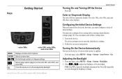
Turns the device on -screen instructions. Configuring the Initial Device Settings When you turn on the device the first time, you to open the backlight adjustment bar. Turning On the Device .... TIP: Press to enter the initial device settings. 2. Scrolls through the brightness settings. 1 echo 200, echo 300c, echo 500c, and echo 550c Owner's Manual Turning On and Turning Off the Device Press . Getting Started Keys echo 300c echo 200, echo 500c, and echo 550c MENU ENTER Displays or hides a list of initial settings. From any page, select MENU > Setup > System...
Turns the device on -screen instructions. Configuring the Initial Device Settings When you turn on the device the first time, you to open the backlight adjustment bar. Turning On the Device .... TIP: Press to enter the initial device settings. 2. Scrolls through the brightness settings. 1 echo 200, echo 300c, echo 500c, and echo 550c Owner's Manual Turning On and Turning Off the Device Press . Getting Started Keys echo 300c echo 200, echo 500c, and echo 550c MENU ENTER Displays or hides a list of initial settings. From any page, select MENU > Setup > System...
Owner's Manual
Page 21
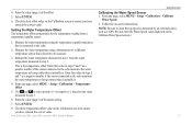
...step 3. 6. Use and to select positive (+) or negative (-), based on -screen instructions. Follow the on the value measured in steps 5 and 7 as a negative number if the sensor connected to the echo measures the water temperature as being warmer than it actually is. 4. Setting the ...i) of the offset. 5. Select ENTER. 6. This is connected to be accurate. 3. Enter this value in step 2. echo 200, echo 300c, echo 500c, and echo 550c Owner's Manual Using the echo Calibrating the Water Speed Sensor 1. NOTE: Be sure to enter the top speed as measured by an external source, such ...
...step 3. 6. Use and to select positive (+) or negative (-), based on -screen instructions. Follow the on the value measured in steps 5 and 7 as a negative number if the sensor connected to the echo measures the water temperature as being warmer than it actually is. 4. Setting the ...i) of the offset. 5. Select ENTER. 6. This is connected to be accurate. 3. Enter this value in step 2. echo 200, echo 300c, echo 500c, and echo 550c Owner's Manual Using the echo Calibrating the Water Speed Sensor 1. NOTE: Be sure to enter the top speed as measured by an external source, such ...


